
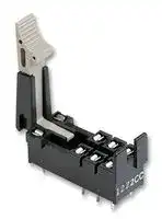


P2R-087P
Relay Socket, Through Hole, PC Pin, 8 Pins, 5 A
- Manufacturer: OMRON INDUSTRIAL AUTOMATION
- Product type: Relay Sockets
- SVHC: To Be Advised
- No. of Pins: 8Pins
- Product Range: -
- Current Rating: 5A
- Voltage Rating: -
- Socket Mounting: Through Hole
- Socket Terminals: PC Pin
| Delivery and price | |
|---|---|
| Units per pack | 50 |
| Price | 4.06 € |
| Current stock | 10+ |
| Lead time | 30 days |
CSM_G2R- _ -S_(S)_DS_E_1_7

## **General-purpose Relay G2R-** @ **-S (S)**

## **Slim and Space-saving Power Plug-in Relay**

- Reduces wiring work by 60% when combined with the

- P2RF- @ -PU Push-In Plus Socket

**==> picture [24 x 14] intentionally omitted <==**

**----- Start of picture text -----**<br>
LR<br>**----- End of picture text -----**<br>


- (according to actual OMRON measurements).

- Lockable test button models available.

- Built-in mechanical operation indicator.

- Provided with nameplate.

- AC type is equipped with a coil-disconnection self-diagnostic function (LED type).

- High switching power (1-pole: 10 A).

For the most recent information on models that have been certified for safety standards, refer to your OMRON website.

## **Model Number Structure**

## **Model Number Legend**

> **G2R -      -** ~~UO~~ **S** ~~OU~~ **(** ~~_~~ **S)**

**1 2 3 4 5**

## **1. Number of Poles**

- 1: 1 pole

- 2: 2 poles

## **4. Rated Coil Voltage**

**5. Mechanical operation indicator and Nameplate**

- (S): Models with mechanical operation indicator and Nameplate

## **2. Terminals**

- S: Plug-in

## **3. Classification**

Blank: General-purpose

- N: LED indicator

D: Diode

ND: LED indicator and diode NI: LED indicator with test button NDI: LED indicator and diode with test button

**Note:** Contact your OMRON representative for Relays with gold-plated contacts.

## **Ordering Information** ~~a~~

**When your order, specify the rated voltage.**

## **List of Models**

|**Classification**|**Coil ratings**<br>~~ee~~|**Contact form**<br>~~eee~~|**Contact form**<br>~~eee~~|
|---|---|---|---|
|||**SPDT**<br>~~eee~~|**DPDT**|
|General-purpose|AC 24, 48, 110, 120, 230, 240<br>DC 6, 12, 24, 48<br>~~ee ~~<br>~~=~~|**G2R-1-S (S)**<br> ~~eee~~<br>~~PO~~<br>~~=~~|**G2R-2-S (S)**|
|LED indicator||**G2R-1-SN (S)**<br>~~=~~|**G2R-2-SN (S)**|
|LED indicator with test button||**G2R-1-SNI (S)**<br>~~=~~<br>~~PO~~|**G2R-2-SNI (S)**|
|Diode|DC 6, 12, 24, 48<br>~~=~~|**G2R-1-SD (S)**<br>~~=~~|**G2R-2-SD (S)**|
|LED indicator and diode||**G2R-1-SND (S)**<br>~~=~~<br>~~PO~~|**G2R-2-SND (S)**|
|LED indicator and diode with test button||**G2R-1-SNDI (S)**<br>~~=~~<br>~~Po~~|**G2R-2-SNDI (S)**|


- **Note: 1.** The standard models are compliant with UL/CSA and VDE standards. Also, an EC compliance declaration has been made for combinations with the P2RF- @ -E, P2RF- @ -S and P2RF- @ -PU. The Relays bear the CE Marking.

   **2.** Refer to _Connecting Sockets_ , below, for applicable Socket models.

   **3.** When ordering, add the rated coil voltage and "(S)" to the model number. Rated coil voltages are given in the coil ratings table. Example: G2R-1-S 12 VDC (S)

      - Rated coil voltage

**1**

**G2R-** @ **-S (S)**

## **Accessories (Order Separately) Connecting Sockets**

|||**Track/surface-mounting Socket**|**Track/surface-mounting Socket**|**Back-mounting Socket**|**Back-mounting Socket**|
|---|---|---|---|---|---|
|**Applicable Relay model**||**Push-In Plus**<br>**Terminal Blocks**|**Screw terminals ***|**PCB terminals**|**Solder terminals**|
|**No. of poles**||**Model**|**Models**|**Models**|**Model**|
|**1 pole**|**G2R-1-S (S)**|**P2RF-05-PU**|**P2RFZ-05-E**<br>**P2RF-05**<br>**P2RF-05-E**|**P2R-05P**<br>**P2R-057P**|**P2R-05A**|
|**2 poles**|**G2R-2-S (S)**|**P2RF-08-PU**|**P2RFZ-08-E**<br>**P2RF-08**<br>**P2RF-08-E**|**P2R-08P**<br>**P2R-087P**|**P2R-08A**|


*The structure of P2RF- @ -E models provides finger protection. Round terminals cannot be used. Use forked crimp terminals.

## **Accessories for Push-In Plus Terminal Block Sockets (P2RF-** @ **-PU) Short Bars**

|**Pitch**|**No. of poles**|**Colors**|**Model***|**Minimum order (quantity)**|
|---|---|---|---|---|
|7.75 mm|2|Red (R)<br>Blue (S)<br>Yellow (Y)|**PYDN-7.75-020**@|10|
||3||**PYDN-7.75-030**@||
||4||**PYDN-7.75-040**@||
||20||**PYDN-7.75-200**@||
|15.5 mm|8||**PYDN-15.5-080**@||


**Note:** Use the Short Bars for crossover wiring within one Socket or between Sockets.

- Replace the box ( @ ) in the model number with the code for the covering color.

## **Labels**

**==> picture [170 x 43] intentionally omitted <==**

**----- Start of picture text -----**<br>
Model Minimum order (sheet)<br>(quantity per sheet)<br>5<br>XW5Z-P4.0LB1<br>1 sheet (60 pieces)<br>**----- End of picture text -----**<br>


## **Accessories for Screw Terminal Sockets (P2RFZ-** @ **-E) Short Bars**

|**Pitch**|**No. of poles**|**Colors**|**Model**|**Minimum order (set)**|
|---|---|---|---|---|
|6.8 mm|10|Blue (S)|**P2DN-6.8-100S**|1<br>One set (order unit) contains<br>10 short bars and 20 caps.|
|15.7 mm|10||**P2DN-15.7-100S**||


**Note: 1.** Use the Short Bars for crossover wiring within one Socket or between Sockets. **2.** Cannot be used on the P2RF- @ -E.

## **Labels**

|**Model**|**Minimum order (sheet)**<br>**(quantity per sheet)**|
|---|---|
|**XW5Z-P2.5LB1**|5<br>1 sheet (72 pieces)|


## **Accessories for Short Bars (P2DN) Cap**

|**Model**|**Minimum order (bag)**|
|---|---|
|**P2DN-CP100**|1<br>(100 pcs./bag)|


## **Mounting Tracks**

|**Applicable Socket**|**Description**|**Description**|**Model**|**Minimum order**<br>**(quantity)**|
|---|---|---|---|---|
|Track-connecting Socket|Mounting track|50 cm (l) × 7.3 mm (t):|**PFP-50N**|---|
|||1 m (l) × 7.3 mm (t):|**PFP-100N**||
|||1 m (l) × 16 mm (t):|**PFP-100N2**||
||End plate *1||**PFP-M**|10|
||Spacer||**PFP-S**||
|Back-connectingSocket|Mountingplate *2||**P2R-P**|1|


- *1.When mounting DIN rail, please use End Plate (PFP-M).

- *2.Used to mount several P2R-05A and P2R-08A Connecting Sockets side by side.

**2**

**G2R-** @ **-S (S)**

**Specifications**

## **Coil Ratings**

|**Rated voltage**|**Rated voltage**|**Rated current***|**Rated current***|**Coil**<br>**resistance**|**Coil inductance (H)**<br>**(ref. value)**|**Coil inductance (H)**<br>**(ref. value)**|**Must**<br>**operate**<br>**voltage**|**Must**<br>**release**<br>**voltage**|**Max.**<br>**voltage**|**Power**<br>**consumption**<br>**(approx.)**|
|---|---|---|---|---|---|---|---|---|---|---|
|||**50 Hz**|**60 Hz**||**Armature**<br>**OFF**|**Armature**<br>**ON**|**% of rated voltage**||||
|**AC**|**24 V**|43.5 mA|37.4 mA|253Ω|0.81|1.55|80% max.|30% max.|110%|0.9 VA at 60 Hz|
||**48 V**|21.8 mA|18.8 mA|1,040Ω|3.12|6.17|||||
||**110 V**|9.5 mA|8.2 mA|5,566Ω|13.33|26.83|||||
||**120 V**|8.6 mA|7.5 mA|7,286Ω|16.13|32.46|||||
||**230 V**|4.4 mA|3.8 mA|27,172Ω|72.68|143.90|||||
||**240 V**|4.2 mA|3.7 mA|27,800Ω|90.58|182.34|||||
||||||||||||
|**Rated voltage**||**Rated current***||**Coil**<br>**resistance**|**Coil inductance (H)**<br>**(ref. value)**||**Must**<br>**operate**<br>**voltage**|**Must**<br>**release**<br>**voltage**|**Max.**<br>**voltage**|**Power**<br>**consumption**<br>**(approx.)**|
||||||**Armature**<br>**OFF**|**Armature**<br>**ON**|**% of rated voltage**||||
|**DC**|**6 V**|87.0 mA||69Ω|0.25|0.48|70% max.|15% min.|110%|0.53 W|
||**12 V**|43.2 mA||278Ω|0.98|2.35|||||
||**24 V**|21.6 mA||1,113Ω|3.60|8.25|||||
||**48 V**|11.4 mA||4,220Ω|15.2|29.82|||||


- **Note: 1.** The rated current and coil resistance are measured at a coil temperature of 23°C with tolerances of +15%/-20% for the AC rated current and ±10% for the DC coil resistance.

   **2.** The AC coil resistance and inductance values are reference values only (at 60 Hz).

   **3.** Operating characteristics were measured at a coil temperature of 23°C.

   **4.** The maximum voltage is the maximum possible value of the voltage that can be applied to the relay coil. It is not the maximum voltage that can be applied continuously.

## **Contact Ratings**

|**Contact Ratings**|||||
|---|---|---|---|---|
|**Number of poles**|1 pole||2 poles||
|**Load**|Resistive load<br>(cosφ= 1)|Inductive load<br>(cosφ= 0.4; L/R = 7 ms)|Resistive load<br>(cosφ= 1)|Inductive load<br>(cosφ= 0.4; L/R = 7 ms)|
|**Rated load**|10 A at 250 VAC;<br>10 A at 30 VDC|7.5 A at 250 VAC;<br>5 A at 30 VDC|5 A at 250 VAC;<br>5 A at 30 VDC|2 A at 250 VAC; 3 A at<br>30 VDC|
|**Rated carry current**|10 A||5 A||
|**Max. switching voltage**|440 VAC, 125 VDC||380 VAC, 125 VDC||
|**Max. switching current**|10 A||5 A||
|**Max. switching power**|2,500 VA,<br>300 W|1,875 VA,<br>150 W|1,250 VA,<br>150 W|500 VA,<br>90 W|
|**Failure rate (reference value) ***|100 mA at 5 VDC||10 mA at 5 VDC||


**Note:** P level: λ 60 = 0.1 x 10[-6] /operation

- *This value was measured at a switching frequency of 120 operations per minute.

**3**

**G2R-** @ **-S (S)**

## **Characteristics**

|**Item**|**1 pole**|**2 poles**|
|---|---|---|
|**Contact configration**|SPDT||
|**Contact structure**|Single||
|**Contact resistance**|100 mΩmax.||
|**Operate (set) time**|15 ms max.||
|**Release (reset) time**|AC: 10 ms max.; DC: 5 ms max.<br>(w/built-in diode: 20 ms max.)|AC: 15 ms max.; DC: 10 ms max.<br>(w/built-in diode: 20 ms max.)|
|**Max. operating**<br>**frequency**|Mechanical:<br>18,000 operations/hr<br>Electrical:<br>1,800 operations/hr (under rated load)||
|**Insulation resistance**|1,000 MΩmin. (at 500 VDC)||
|**Dielectric strength ***|5,000 VAC, 50/60 Hz for 1 min between coil and<br>contacts;<br>1,000 VAC, 50/60 Hz for 1 min between contacts of<br>same polarity|5,000 VAC, 50/60 Hz for 1 min between coil and contacts;<br>3,000 VAC, 50/60 Hz for 1 min between contacts of different polarity<br>1,000 VAC, 50/60 Hz for 1 min between contacts of same polarity|
|**Vibration resistance**|Destruction:<br>10 to 55 to 10 Hz, 0.75 mm single amplitude (1.5 mm double amplitude)<br>Malfunction:<br>10 to 55 to 10 Hz, 0.75 mm single amplitude (1.5 mm double amplitude)||
|**Shock resistance**|Destruction:<br>1,000 m/s2<br>Malfunction:<br>200 m/s2when energized; 100 m/s2when not energized||
|**Endurance**|Mechanical:<br>AC coil: 10,000,000 operations min.;<br>DC coil: 20,000,000 operations min. (at 18,000 operations/hr)<br>Electrical:<br>100,000 operations min. (at 1,800 operations/hr under rated load)||
|**Ambient temperature**|Operating:<br>–40°C to 70°C (with no icingor condensation)||
|**Ambient humidity**|Operating:<br>5% to 85%||
|**Weight**|Approx. 20g||


**Note:** Values in the above table are the initial values.

*These values are relay only. Prease refer to the “Products Related to Common Sockets and DIN Tracks Data Sheet” for connecting sockets.

## **Approved Standards UL 508 (File No. E41643)**

|**Model**|**Contact**<br>**form**|**Coil ratings**|**Contact ratings**|**Opera-**<br>**tions**|
|---|---|---|---|---|
|G2R-1-S (S)|SPDT|5 to 110 VDC<br>6 to 240 VAC|10 A, 30 VDC (resistive)<br>10 A, 250 VAC (general use)|100 × 103|
||||TV-3 (NO contact only)|25 × 103|
|G2R-2-S (S)|DPDT||5 A, 30 VDC (resistive)<br>5 A, 250 VAC (general use)|100 × 103|
||||TV-3 (NO contact only)|25 × 103|


## **CSA 22.2 No.0, No.14 (File No. LR31928)**

|**Model**|**Contact**<br>**form**|**Coil ratings**|**Contact ratings**|**Opera-**<br>**tions**|
|---|---|---|---|---|
|G2R-1-S (S)|SPDT|5 to 110 VDC<br>6 to 240 VAC|10 A, 30 VDC (resistive)<br>10 A, 250 VAC (general use)|100 × 103|
||||TV-3 (NO contact only)|25 × 103|
|G2R-2-S (S)|DPDT||5 A, 30 VDC (resistive)<br>5 A, 250 VAC (general use)|100 × 103|
||||TV-3 (NO contact only)|25 × 103|


## **IEC/VDE (Certificate No. 40015012 EN 61810-1)**

|**Contact**<br>**form**|**Coil ratings**|**Contact ratings**|**Operations**|
|---|---|---|---|
|1 pole|6, 12, 24, 48 VDC<br>24, 110, 120, 230,<br>240 VAC|5 A, 440 VAC (cosφ= 1.0)<br>10 A, 250 VAC (cosφ= 1.0)<br>10 A, 30 VDC (0 ms)|100 × 103|
|2 poles|6, 12, 24, 48 VDC<br>24, 110, 120, 230,<br>240 VAC|5 A, 250 VAC (cosφ=1.0)<br>5 A, 30 VDC (0 ms)|100 × 103|


## **LR**

|**Number**<br>**of poles**|**Coil ratings**|**Contact ratings**|**Operations**|
|---|---|---|---|
|1 pole|5 to 110 VDC<br>6 to 240 VDC|10 A, 250 VAC (general use)<br>7.5 A, 250 VAC (PF0.4)<br>10 A, 30 VDC (resistive)<br>5A, 30VDC (L/R=7ms)|100 × 103|
|2 poles|5 to 110 VDC<br>6 to 240 VDC|5 A, 250 VAC (general use)<br>2 A, 250 VAC (PF0.4)<br>5 A, 30 VDC (resistive)<br>3A, 30VDC (L/R=7ms)|100 × 103|


**4**

**G2R-** @ **-S (S)**

**Engineering Data**

## **Maximum Switching Power**

**==> picture [325 x 548] intentionally omitted <==**

**----- Start of picture text -----**<br>
G2R-1-S (S) G2R-2-S (S)<br>100 100<br>= AC inductive load (cosφ = 0.4) it AC resistive load l || A<br>AC inductive load<br>10 10 (cosφ = 0.4) AC resistive  load<br>DC resistive<br>=2Sei load AW alll SihSSS DC resistive   —<br>LT DC inductive load   Tn ANIL tf HT] r_| load NANT<br>1 (L/R = 7 ms) 1 DC inductive load<br>ARG HO \ONG<br>(L/R = 7 ms)<br>a| — enh Fee<br>mA Soo oh oe<br>0.11 a 10 100 1000 0.11 rrr 10 CT 100 1000<br>Switching voltage (V) Switching voltage (V)<br>Endurance<br>G2R-1-S (S) G2R-2-S (S)<br>5,000 A 10,000 SS<br>5,000<br>Ree REE<br>250-VAC/30-VDC<br>1,000 Renee resistive load i<br>1,000<br>500 250-VAC inductive load  30-VDC inductive load (L/R = 7ms)<br>. ys (cosφ = 0.4) 500 1<br>250-VAC/30-VDC<br>CONRAN PRS resistive load —<br>10050 | 30-VDC inductive load (L/R = 7ms) UNS 100 250-VAC  RNa ee<br> 50 inductive load<br>(cosφ = 0.4)<br>SEeaeaataaoBERRRRERREEEE esa WEPETE———eccecs<br>0 2 4° 5 6 8 10 12 14 0 J 2 3 4 5<br>Switching current (A) Switching current (A)<br>Ambient Temperature vs Maximum Coil Voltage<br>SERRRRREEE200<br>DC coil<br>oe<br>TN AC coil T<br>5 20 30 40 50 60 70 8 90 106<br>Ambient temperature (°C)<br>Switching current (A) Switching current (A)<br> operations)<br>3  operations)<br>Endurance (x10 3<br>Endurance (x10<br>Maximum voltage (%)<br>**----- End of picture text -----**<br>


## **Endurance**

## **Ambient Temperature vs Maximum Coil Voltage**

**5**

**G2R-** @ **-S (S)**

**(Unit: mm)**

## **Dimensions**

**Note:** All units are in millimeters unless otherwise indicated.

## **SPDT Relays**

**==> picture [505 x 260] intentionally omitted <==**

**----- Start of picture text -----**<br>
G2R-1-S (S), G2R-1-SN (S), G2R-1-SNI (S) Terminal Arrangement/Internal Connections<br>G2R-1-SD (S), G2R-1-SND (S), G2R-1-SNDI (S) (Bottom View)<br>G2R-1-S (S) G2R-1-SD (S) (DC)<br>29 max. 13 max. 1 1<br>5 2 4 3 5 2 4 3<br>1b ) [0 Cl |<br>G2R-1-SN (S), G2R-1-SNI (S) (AC) G2R-1-SN (S), G2R-1-SNI (S) (DC)<br>1 1<br>-—— : tp AL ed  '<br>0.5 4.75 5 2 4 3 5 2 4 3<br>| iT (al Ha AT ET nT<br>G2R-1-SND (S), G2R-1-SNDI (S) (DC)<br>5.2 5.2<br>17.5<br>1<br>5 2 4 3<br>HL<br>DC24V<br>max.<br>20 35.5<br>5<br>1<br>.5<br>7<br>**----- End of picture text -----**<br>


## **DPDT Relays**

**G2R-2-S (S), G2R-2-SN (S), G2R-2-SNI (S) G2R-2-SD (S), G2R-2-SND (S), G2R-2-SNDI (S)**

**Terminal Arrangement/Internal Connections (Bottom View)**

~~:~~ **G2R-2-S (S) G2R-2-SD (S) (DC)** 1 2 3 4 ~~[bo~~ 29 max. ~~of~~ 13 max. a 1 2 3 4 ~~wy~~ fb ~~Val |p~~ 8 7 6 5 8 7 6 5 **G2R-2-SN (S), G2R-2-SNI (S) (AC) G2R-2-SN (S), G2R-2-SNI (S) (DC)** 1 2 3 4 1 2 3 4 0.5 2.5 8 7 6 5 8 7 6 5 2.4 **G2R-2-SND (S), G2R-2-SNDI (S) (DC)** 5 5 19.4 1 2 3 4 8 7 6 5 5 atl ~~an~~ i ~~m:~~

**6** omrRon ~~a~~

**G2R-** @ **-S (S)**

## **Track/Surface Mounting Sockets**

## **P2RF-05-PU**

**==> picture [381 x 474] intentionally omitted <==**

**----- Start of picture text -----**<br>
57.5<br>Terminal Arrangement/<br>Internal Connection Diagram<br>(Top View)<br>53.1 A2 A1 Mounting Hole<br>30.8 Dimensions<br>(1) (5)<br>28.1<br>(4.2) 25.6<br>Two M3 screw<br>holes or<br>two 3.5-dia. holes<br>108<br>90 35.3 Release lever<br>12<br>(2)<br>14<br>27.35 (3)<br>11<br>(4)<br>Note:  Pull out the hooks to<br>a (4.2) 3.9 e 25.6 s Note:  The numbers in  mount the Socket<br>15.5 34.3 parentheses are  with screws.<br>43 traditionally used<br>al 52.1 oF terminal numbers.<br>57.5<br>Terminal Arrangement/<br>Internal Connection Diagram<br>53.1 (Top View)<br>30.8 A2 A1 Mounting Hole<br>28.1 Dimensions<br>(1) (8)<br>(4.2) 25.6<br>Two M3 screw<br>holes or<br>two 3.5-dia. holes<br>90 35.3 Release lever 108<br>12 22<br>(2) (7)<br>27.35 14 24<br>(4) (5)<br>11 21<br>(4.2) 3.9 25.6 (3) (6) Note:  Pull out the hooks to<br>15.5 34.3 mount the Socket<br>43 Note:  The numbers in  with screws.<br>52.1 parentheses are<br>traditionally used<br>terminal numbers.<br>**----- End of picture text -----**<br>


## **P2RF-08-PU**

## **Accessories for P2RF-** @ **-PU**

|**Application**|**Pitch**|**No. of**<br>**poles**|**L (Length)**|**Colors**|**Model***|**Maximum**<br>**carry current**|
|---|---|---|---|---|---|---|
|For Contact<br>terminals<br>(common)|7.75 mm|2|15.1|Red (R)<br>Blue (S)<br>Yellow (Y)|**PYDN-7.75-020**@|20 A|
|||3|22.85||**PYDN-7.75-030**@||
|||4|30.6||**PYDN-7.75-040**@||
|||20|154.6||**PYDN-7.75-200**@||
|For Coil<br>terminals|15.5 mm|8|115.85||**PYDN-15.5-080**@||


## **Short Bars**

## **PYDN-7.75-** @@ **(7.75 mm)**

**==> picture [124 x 60] intentionally omitted <==**

**----- Start of picture text -----**<br>
3.90<br>L<br>18.5<br>12<br>2.25 1.57<br>**----- End of picture text -----**<br>


* Replace the box ( @ ) in the model number with the code for the covering color.

**Note: 1.** Use the Short Bars for crossover wiring within one Socket or between Sockets.

## **PYDN-15.5-080** @ **(15.5 mm)**

**2.** When using short bar to coil terminals of PYF- @@ -PU, make sure to use PYDN-31.0080 @ (31 mm).

3.90

When using short bar to coil terminals of P2RF- @@ -PU, make sure to use PYDN-15.5080 @ (15.5 mm).

**==> picture [119 x 56] intentionally omitted <==**

**----- Start of picture text -----**<br>
115.85<br>18.5<br>12<br>re<br>2.25 1.57<br>**----- End of picture text -----**<br>


**7**

**G2R-** @ **-S (S)**

## **P2RFZ-05-E**

**==> picture [412 x 519] intentionally omitted <==**

**----- Start of picture text -----**<br>
Terminal Arrangement/ Mounting Hole<br>5-M3X8 48 max. 2 Internal Connection Diagram Dimensions<br>(Top View)<br>3.2-dia. hole<br>4<br>39.5 (42.3) 2 10.5<br>3<br>78.5 max. 39.5±0.1<br>3.5-dia.  pat (35.8) l g .<br>hole 35.5<br>M3 or<br>3.5-dia.<br>hole<br>= af 17.2 AN<br>4 31 max. 5 1<br>16 max.<br>61 max.<br>Terminal Arrangement/ Mounting Hole<br>8-M3X8 48 max. 2 Internal Connection Diagram Dimensions<br>vr 2 | (Top View) 3.2-dia. hole<br>10.5<br>(42.3) 6 3<br>39.5 7 2<br>5 4<br>78.5 max. 39.5±0.1<br>(35.8)<br>3.5-dia.  | Se re [ e3 ) ie<br>hole 35.5 M3 or<br>3.5-dia.<br>hole<br>17.2<br>4 8 1<br>31 max.<br>16 max.<br>61 max.<br>@ -E<br>15.7±0.1<br>6.8±0.1<br>2.9 9<br>15.4 max.<br>8.7 max.<br>Hehusoeonasnonn 152.7 max. ei 4<br>BLAM Sah CaM SAR AMSa Da A 2.5 max. a7 [FT]<br>2.9 15.7±0.1<br>1.6-dia.  9<br>15.4 max.<br>8.7 max.<br>boat Th 152.7 max. gh i<br>2.5 max.<br>**----- End of picture text -----**<br>


## **P2RFZ-08-E**

## **Accessories for P2RFZ-** @ **-E Short Bars P2DN-6.8-100S (6.8 mm)** Maximum carry current: 20A Witte

**P2DN-15.7-100S (15.7 mm)** Maximum carry current: 20A

**Note:** Each Short Bar set comes with 20 Caps.

**==> picture [337 x 113] intentionally omitted <==**

**----- Start of picture text -----**<br>
Accessories for P2DN<br>Cap<br>P2DN-CP100 5.2 max.<br>4 max.<br>rf re I<br>6 max.<br>**----- End of picture text -----**<br>


**8** omRON ~~a~~

**G2R-** @ **-S (S)**

## **P2RF-05-E**

**==> picture [47 x 8] intentionally omitted <==**

**----- Start of picture text -----**<br>
P2RF-08-E<br>**----- End of picture text -----**<br>


**==> picture [398 x 316] intentionally omitted <==**

**----- Start of picture text -----**<br>
7±0.2<br>Terminal Arrangement Mounting Holes<br>2 (Top View) (for Surface Mounting)<br>Five, M3.5´7 48 max.<br>3.2-dia.<br>4 (11) hole<br>39.5 (12) 2<br>3 (14)<br>85.5 max. 35.5 39.5±0.1<br>3.5-dia.<br>hole<br>M3 or<br>5 3.5-dia.<br>(A1) 1 hole<br>L (A2) P<br>4 11.5<br>16.0 max. 61 max.<br>Note:    Pin numbers in parentheses apply to DIN standard.<br>6 [+0.2] −0.1<br>Terminal Arrangement Mounting Holes<br>2 (Top View) (for Surface Mounting)<br>2 1.5 Eight, M3´8 48.0 max. 3<br>(21) 6 3 (11) 3.2-dia.<br>(22) 7 2 (12) hole<br>39.5 (24) 5 4 (14)<br>35.5<br>85.5  |e ark =|@ 39.5±0.1<br>max.<br>3.5-dia. hole 8 (A1) M3 or<br>(A2) 1 3.5-dia. hole<br>4 11.5<br>61.0<br>max.<br>16.0 max.<br>**----- End of picture text -----**<br>


**==> picture [510 x 306] intentionally omitted <==**

**----- Start of picture text -----**<br>
P2RF-05 7 2 Terminal Arrangement Mounting Holes<br>On Five, M3.5 x 8 (Top View) (for Surface Mounting)<br>4-dia. holes 4.2-dia. hole<br>71.5 max. 35.5<br>30±0.05<br>5: le L : fe p | e ni<br>4 19.5 M3 or 3.2-dia.<br>19.5 max. 30 max.<br>hole<br>54 max.<br>| = Sie<br>=e<br>P2RF-08<br>2<br>7<br>Eight, M3.5 x 8 Terminal Arrangement Mounting Holes<br>4-dia. holes (Top View) (for Surface Mounting)<br>4.2-dia. hole<br>71.5 max. 35.5<br>30±0.05<br>19.5<br>4<br>19.5 max. 30 max. M3 or 3.2-dia.<br>54 max. hole<br>an<br>~ il<br>**----- End of picture text -----**<br>


**9**

**G2R-** @ **-S (S)**

## **Mounting Height of Relay with Track/Surface Mounting Sockets**

**==> picture [393 x 122] intentionally omitted <==**

**----- Start of picture text -----**<br>
P2RF-05-PU G2R-@-S (S)  P2RF-08-PU G2R-@-S (S)<br>Relay Relay<br>P2RF-05ーPU P2RF-08ーPU<br>Socket Socket<br>63.6 63.6<br> 28.1   28.1<br> (3.9)  (3.9)<br>**----- End of picture text -----**<br>


**==> picture [155 x 123] intentionally omitted <==**

**----- Start of picture text -----**<br>
P2RFZ-E<br>G2R-@-S (S)<br>Relay<br>P2RFZ-@-E<br>Socket<br>67.0 70.5<br>**----- End of picture text -----**<br>


**==> picture [336 x 115] intentionally omitted <==**

**----- Start of picture text -----**<br>
P2RF- @ G2R-@-S (S)  P2RF- @ -E G2R-Relay@-S (S)<br>Relay<br>P2RF-@-E<br>Socket<br>P2RF-@<br>Socket<br>66.5 [62.0] 67.0 70.5<br>**----- End of picture text -----**<br>


**10**

**G2R-** @ **-S (S)**

## **Back-connecting Sockets**

**==> picture [472 x 636] intentionally omitted <==**

**----- Start of picture text -----**<br>
Terminal Arrangement  Mounting Holes<br>P2R-05P (1-pole) 14.5 max. (Bottom View) Tolerance: ±0.1<br>1 4 7<br>4<br>Five,<br>6 1.6-dia.<br>4.5 6 holes<br>15 35.5 max.<br>| 1.2 \nmall 4.5 ms<br>4 15<br>3.5<br>J&LGee 1.5 4<br>(5)<br>7 4<br>7<br>36.5 max.<br>P2R-08P (2-pole)<br>Terminal Arrangement  Mounting Holes<br>4 7 14.5 max. (Bottom View)<br>0.3<br>7.5 Eight, 1.3-dia. holes<br>5<br>5<br>35.5 max. 5<br>20<br>1 5<br>2.8 20<br>a | jee bata<br>1.5<br>(4.3)<br>7.5<br>Terminal plate thickness: 0.3 36.5 max.<br>4.5<br>P2R-05A (1-pole) 7.5 14.5 max.<br>1.2<br>0.3<br>Terminal Arrangement<br>6.7 (Bottom View)<br>3.8<br>16.7 5 35.5 max.<br>Panel Cutout<br>Five, 3 x 1.8-dia. holes<br>13.6±0.1<br>6<br>Terminal plate thickness: 0.3 36.5 max.<br>30.5±0.2<br>P2R-08A (2-pole) 6.5 7.5 14.5 max.<br>1.2<br>0.3 a 00<br>5<br>5 aliI rome) 0© © © lil<br>20 35.5 max. Recommended thickness of<br>2.6 the panel is 1.6 to 2.0 mm<br>1.52.8 ean a<br>ro Eight, 3 x 1.2-dia. holes | lee<br>7.5<br>Terminal plate thickness: 0.3 36.5 max.<br>**----- End of picture text -----**<br>


**11**

**G2R-** @ **-S (S)**

**==> picture [455 x 247] intentionally omitted <==**

**----- Start of picture text -----**<br>
P2R-057P (1-pole) 14 max. 16.4 Terminal Arrangement Mounting Holes<br>0.7 8.7 1 10.4 3.5 1 (Bottom View) 4±0.1 Five,<br>1.6-dia.<br>6 holes<br>37 max.29.6 4.515 6±0.1<br>4<br>1 8.75 4.5±0.1 15±0.1<br>8.7 7.4 4±0.1<br>5<br>7±0.1<br>P= 41 max.<br>P2R-087P (2-pole) 14 max. 16.4 Terminal Arrangement Mounting Holes<br>qd 7.5 1 oO 10.4 3.5 0.3 (Bottom View) 7.5 Eight, 1.3-dia.<br>5 holes<br>5<br>37 max.29.1 1 20 5<br>5<br>8.1<br>20<br>i fa t j °° | | —<br>8.9 7.4<br>(8.1)<br>41 max.<br>**----- End of picture text -----**<br>


## **Mounting Height of Relay with Back-connecting Sockets**

**==> picture [507 x 240] intentionally omitted <==**

**----- Start of picture text -----**<br>
P2R- @ P P2R- @ A P2R- @ 7P<br>G2R-@-S (S) Relay<br>G2R-@-S (S) Relay<br>44.5 47.5 G2R-@-S (S) Relay<br>P2R-@P  38.0<br>P2R-@A<br>Socket Socket P2R-@7P<br>Socket<br>A y og| /<br>eT<br>Mounting Tracks<br>PFP-100N, PFP-50N PFP-100N2<br>= ———<br>16<br>—— 7.3±0.15 es=<br>4.5<br>4.5<br>35±0.3 27±0.15 35±0.3 27 24 29.2<br>es*aal 15 25 10 251,000 (500) 25 10 25 15 (5)  L 1 15 25 10 25 1,000 25 10 25 15 Toe 1 1.5<br>**----- End of picture text -----**<br>


## **Mounting Tracks**

It is recommended to use a panel 1.6 to 2.0 mm thick.

**12**

**G2R-** @ **-S (S)**

## **End Plate**

**==> picture [233 x 248] intentionally omitted <==**

**----- Start of picture text -----**<br>
PFP-M 10<br>6.2<br>1.8<br>1<br>50 35.5 35.3<br>1.8<br>11.5 1.3<br>10<br>M4 x 8 pan  4.8<br>head screw<br>Mounting Plate<br>P2R-P<br>90<br>R2.25 4.5 13.6<br>10-Ellipse hole<br>3.4<br>49 42 [±0.1] 30.5<br>(itay<br>Square hole mae 18 [±0.15] 18 [±0.15] 18 [±0.15] 18 [±0.15]<br>9 [±0.1] 72 [±0.2] 9 [±0.1] t=1.6 mm<br>**----- End of picture text -----**<br>


## **Mounting Plate**

## **P2R-P**

## **Spacer**

**==> picture [214 x 97] intentionally omitted <==**

**----- Start of picture text -----**<br>
16<br>PFP-S 5 12<br>34.8<br>44.3<br>16.5<br>**----- End of picture text -----**<br>


**13**

**G2R-** @ **-S (S)**

## **Safety Precautions**

**Be sure to read the** _**Common Precautions for All Relay**_ **in the website at the following URL: http://www.ia.omron.com/.**

**Refer to** _**Products Related to Common Sockets and DIN Tracks**_ **for precautions on the applicable Sockets. Refer to** _**PYF-**_ @@ _**-PU/P2RF-**_ @@ _**-PU**_ **for precautions on Push-In Plus Terminal Block Sockets. Warning Indications** • **Indicates a potentially hazardous situation which, if not avoided, may result CAUTION** be possible to attach the insulating cap. **in minor or moderate injury or in property damage. Supplementary comments on what to do Precautions for or avoid doing to prevent failure to Correct Use operate, malfunction, or undesirable effects on product performance.** ~~om~~ Ve **Cation** b : My 4/ ‘ f • Do not use the test button for any purpose other than testing. Be sure not to touch the test button accidentally as this will turn the contacts ON. Before using the test button, confirm that circuits, the load, and any other connected item will operate safely. • • Check that the test button is released before turning ON relay cired cap to protect the charger part. cuits.

   - **for precautions on the applicable Sockets.** • When cutting with a tool, insert the tool from the plastic part and cut along the slot in the plastic part between terminals. If you cut a part other than the slot in the plastic part between terminals, it may not be possible to attach the insulating cap. Ve

   - When using a cut short-circuit bar (P2DN), always use the provided cap to protect the charger part.

- If the test button is pulled out too forcefully, it may bypass the momentary testing position and go straight into the locked position.

• Use an insulated tool when you operate the test button.

## **Precautions for Correct Use** ~~————~~

## **About the Built-in Diodes**

The diodes that are built into the Relays are designed to absorb reverse voltage from the Relay’s coil. If a large surge in voltage is applied to the diode from an external source, the element will be destroyed.

**==> picture [24 x 37] intentionally omitted <==**

**----- Start of picture text -----**<br>
,<br>**----- End of picture text -----**<br>


- The proper orientation for installing the short-circuit bar is with the molded part facing inward.

If there is the possibility of large voltage surges that could be applied to the elements from an external source, take any necessary surge absorption measures.

## **Latching Levers**

- Turn OFF the power supply when operating the latching lever. After you use the latching lever always return it to its original state.

- Do not use the latching lever as a switch.

- The latching lever can be used for 100 operations minimum.

## **Relay Replacement**

To replace the Relay, turn OFF the power supply to the load and Relay coil sides to prevent unintended operation and possible electrical shock.

## **Coil tape color**

Pink tape is used for the AC coil type and blue tape is used for the DC coil type, making it easy to distinguish AC and DC.

## **Using a short-circuit bar**

- Use the short-circuit bar that is suitable for the socket you are using and the location of use.

- Note that the P2DN short-circuit bar for the P2RFZ-E Socket has both a short-circuit bar for shorting coil terminals and a short-circuit bar for shorting contact COM terminals.

- The short-circuit bar can be cut to match any number of poles. Cut with a tool as appropriate for the number of relays and sockets. When using a cut short-circuit bar, take care to avoid injuring yourself on the cut surface.

- Use the short-circuit bar to short-circuit two or more coil terminals, or two or more contact COM terminals.

- Do not use a deformed short-circuit bar. Risk of failure, malfunctioning, or deterioration of characteristics.

- In socket terminals, insert the short-circuit bar in the correct orientation all the way into all terminals, and then secure with screws.

- Install the short -circuit bar before wiring.

## **Equivalent Labels from Other Companies and Recommended Label Printers**

Use the following label printer.

The following table gives the manufacturer’s model number as of March 2017.

|**Manufacturer**|**Omron**|**Phoenix**<br>**Contact**|**Weidmuller**|**Cembre**|
|---|---|---|---|---|
|Label|XW5Z-P4.0LB1|UCT-TM6|MF 10/6|MG-CPM-04<br>41391|
||XW5Z-P2.5LB2|UCT-TMF5|---|---|
|Label printer|---*|BLUEMARK<br>CLED,<br>THERMOMA<br>RK CARD<br>SET PLUS,<br>THERMOMA<br>RK CARD|PrintJet<br>ADVCANCED,<br>Plotter MCP<br>Plus,<br>Plotter MCP<br>Basic|Markingenius<br>MG3|


* When using a printing tool, use a Phoenix Contact label printer. **Note:** Ask the label manufacturer or printer manufacturer for details.

**14**

**OMRON AUTOMATION AMERICAS HEADQUARTERS •** Chicago, IL USA **•** 847.843.7900 **•** 800.556.6766 **•** automation.omron.com

## **OMRON CANADA, INC. • HEAD OFFICE**

Toronto, ON, Canada • 416.286.6465 • 866.986.6766 • automation.omron.com

## **OMRON ELECTRONICS DE MEXICO • HEAD OFFICE**

Ciudad de México • 52.55.5901.4300 • 01.800.386.6766 • mela@omron.com

## **OMRON ELETRÔNICA DO BRASIL LTDA • HEAD OFFICE**

São Paulo, SP, Brasil • 55 11 5171-8920 • automation.omron.com

## **OMRON ARGENTINA • SALES OFFICE**

Buenos Aires, Argentina • +54.11.4521.8630 • +54.11.4523.8483 mela@omron.com

## **OMRON ELECTRONICS DE MEXICO • SALES OFFICE**

San Pedro Garza García, N.L. • 81.12.53.7392 • 01.800.386.6766 • mela@omron. **OTHER OMRON LATIN AMERICA SALES** com

+54.11.4521.8630 • +54.11.4523.8483 • mela@omron.com

## **OMRON ELECTRONICS DE MEXICO • SALES OFFICE**

Eugenio Garza Sada,León, Gto • 01.800.386.6766  • mela@omron.com

## _Authorized Distributor:_

## **Controllers & I/O**

- Machine Automation Controllers (MAC) • Motion Controllers • Programmable Logic Controllers (PLC) • Temperature Controllers • Remote I/O **Robotics** • Industrial Robots • Mobile Robots

## **Operator Interfaces**

- Human Machine Interface (HMI)

## **Motion & Drives**

- Machine Automation Controllers (MAC) • Motion Controllers • Servo Systems • Frequency Inverters **Vision, Measurement & Identification**

- Vision Sensors & Systems • Measurement Sensors • Auto Identification Systems

## **Sensing**

- Photoelectric Sensors • Fiber-Optic Sensors • Proximity Sensors • Rotary Encoders • Ultrasonic Sensors

## **Safety**

- Safety Light Curtains • Safety Laser Scanners • Programmable Safety Systems • Safety Mats and Edges • Safety Door Switches • Emergency Stop Devices • Safety Switches & Operator Controls • Safety Monitoring/Force-guided Relays **Control Components** • Power Supplies • Timers • Counters • Programmable Relays • Digital Panel Meters • Monitoring Products **Switches & Relays** • Limit Switches • Pushbutton Switches • Electromechanical Relays • Solid State Relays **Software** • Programming & Configuration  • Runtime

> J140-E3-02             Note: Specifications are subject to change. © 2020 Omron. All Rights Reserved.

Printed in U.S.A.

_Printed on recycled paper._
Updated at June 6, 2026
With a legacy spanning over 80 years, Omron Industrial Automation is a globally recognized leader in the manufacture of advanced industrial control and automation components. Renowned for their reliability and engineering excellence, Omron delivers comprehensive solutions that enhance efficiency, machine safety, and precision across a wide range of manufacturing environments. Our extensive portfolio of Omron products is heavily focused on their industry-leading sensing and switching technologies. We offer a vast selection of sensors, excelling specifically in high-performance proximity sensors, light sensors, and temperature sensors. Complementing this range are robust switching solutions, featuring a deep inventory of power relays, solid-state relays, safety relays, and essential relay accessories designed for demanding operational requirements. Beyond sensing and switching, Omron is highly regarded for its precision automation and process control equipment. Our selection features highly accurate temperature controllers, versatile process controllers, and sophisticated panel displays and instrumentation. To support these fundamental systems, we also supply dependable Omron power supplies, notably AC/DC converters, alongside vital connectivity components like DIN rail terminal blocks to ensure secure, efficient, and complete industrial setups.
About Novapart
Novapart is a B2B electronic component broker specialising in stock shortages and cost reduction. We source hard-to-find parts and identify compliant alternatives across a catalogue of 410,000+ components from 500+ manufacturers.
Learn more →Stock Shortage Specialist
When a component is unavailable, discontinued or has an unacceptable lead time, we tap into our network of vetted European and Asian distributors to source what you need — without compromising on quality or traceability.
Request a quote →Compliant Alternatives
We identify pin-to-pin, electrically equivalent substitutes that meet the same certifications (RoHS, AEC-Q100, REACH) as your original specification — validated against datasheets, not just part numbers. Often at a lower cost.
BOM Analysis service →