
Image not available
Illustrative purposes only

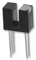
OPB460N11
Optical Switch, OPB460 Series, Photologic®, 0.25 mm, 10K Pullup, 4.5 V to 16 V
⚠️ Reference pricing provided. In case of supply shortages, we will connect you with our trusted procurement partners to ensure your project's continuity.
- Manufacturer: TT ELECTRONICS / OPTEK TECHNOLOGY
- Product type: Optical / Slot Photoelectric Sensors
- Product Range: OPB460 Series
- Sensor Output: 10K Pullup
- Output Current: 14µA
- Supply Voltage DC Max: 16V
- Supply Voltage DC Min: 4.5V
| Delivery and price | |
|---|---|
| Units per pack | 50 |
| Price | 2.61 € |
| Current stock | 10+ |
| Lead time | 30 days |
Datasheet

## Features:

- Choice of pins or wires mounting configuration

- Choice of aperture

- Choice of output configuration

- Choice of opaque or IR transmissive shell material

- Data rates to 250 kBaud

- Low power consumption

The **OPB460** , **OPB470** , **OPB480** and **OPB490** series of Photologic® photo integrated circuit switches provide optimum flexibility for the design engineer.  Building from a standard housing with a 0.125” (3.180 mm) wide slot, a user can specify the type and polarity of TTL output, discrete shell material, aperture width and choice of mounting configurations. **OPB460** through **OPB473** have  0.425” (10.795 mm) PCBoard leads with 0.320” (8.1 mm) spacing. **OPB480** through **OPB493** have 24” (609 mm) 26 AWG wires (UL approved wires).

All devices in this series exhibit performance over supply voltages ranging from 4.5 V to 16.0 V, and may be specified as buffered or inverted with 10 kW Pull-up or Open Collector output.  Devices are also TTI/LSTTL compatible and can drive up to 10 TTL loads.

Custom electrical, wire and cabling and connectors are available.  Contact your local representative or OPTEK for more information.

## **Applications:**

- Mechanical switch replacement

- Speed indication (tachometer)

- Mechanical limit indication

- Edge sensing **Part Number Guide — OPB460, OPB470, OPB480, OPB490 Series**

**OPB 4 X X X 1 1 X**

**==> picture [164 x 82] intentionally omitted <==**

**----- Start of picture text -----**<br>
OPTEK Assembly<br>Photologic™ Sensor Family<br>Discrete Housing Material:<br>6 —  Transmissive Shell, PCBoard Mountable<br>7 —  Opaque Shell, PCBoard Mountable<br>8 —  Transmissive Shell, Wire Termination<br>9 —  Opaque Shell, Wire Termination<br>**----- End of picture text -----**<br>


**All PCBoard Versions RoHS Compliant: Z =** Wire Version RoHS Compliant **Sensor Aperture: 1 =** 0.010” [0.25 mm] **Emitter Aperture: 1 =** 0.010” [0.25 mm] **Mounting Configurations: L —** Emitter side mounting tab only **N —** No mounting tabs **P —** Sensor side mounting tab only

**==> picture [132 x 36] intentionally omitted <==**

**----- Start of picture text -----**<br>
Electrical Specifications:<br>0 —  Buffered 10 kΩ Output<br>1 —  Buffered Open-Collector Output<br>2 —  Inverted 10 kΩ Output<br>**----- End of picture text -----**<br>


**2 —** Inverted 10 kΩ Output **T —** Two mounting tabs **3 —** Inverted Open-Collector Output

**RoHS**

**==> picture [101 x 102] intentionally omitted <==**

**----- Start of picture text -----**<br>
Color-Pin  Description<br>Red-1  Anode<br>Black-2  Cathode<br>White-3  Vcc<br>Blue-4  Output<br>Green-5  Ground<br>**----- End of picture text -----**<br>


**TOLERANCE DIMENSIONS ARE: ± .25mm [± .010”]**

**CONTAINS POLYSULFONE** To avoid stress cracking, we suggest using ND Industries’ **Vibra-Tite** for thread-locking. **Vibra-Tite** evaporates fast without causing structural failure in OPTEK’s molded plastics. **Applies to:  OPB460, OPB470, OPB480, OPB490.**

|Absolute Maximum Ratings (T,= 25° C unless otherwise noted)|Absolute Maximum Ratings (T,= 25° C unless otherwise noted)|
|---|---|
|Storage & Operating Temperature Range|-40° C to +85° C|
|Lead Soldering Temperature [1/16 inch (1.6mm) from the case for 5 sec. with soldering iron](1)|260°C|
|||
|Supply Voltage, VCC(not to exceed 3 seconds)|18 V|
|Diode Forward DC Current|40 mA|
|Diode Reverse DC Voltage|2 V|
|Input Diode Power Dissipation(2)|75 mW|
|||
|Voltage at Output Lead (Open Collector Output)|25 V|
|Output Photologic® Power Dissipation(3)|200 mW|
|||
|Total Device Power Dissipation(4)|275 mW|


Notes:

(1) RMA flux is recommended.  Duration can be extended to 10 seconds maximum when flow soldering.

(2) Derate linearly 1.67 mW/°C above 25° C (OPB460, OPB470) or derate linearly 1.82 mW/°C above 25° C (OPB480, OPB490).

(3) Derate linearly 1.50 mW/°C above 25° C (OPB460, OPB470) or derate linearly 1.64 mW/°C above 25° C(OPB480, OPB490).

(4) Derate linearly 3.17 mW/°C above 25° C (OPB460, OPB470) or derate linearly 3.45 mW/°C above 25° C (OPB480, OPB490).

(5) The OPB460/OPB470 series are terminated with 0.020” square leads designed for printed circuit board mounting.

(6) The OPB480/OPB490 series of switches are terminated with 24” (609.600 mm) of 7-strand 26 AWG, UL rated insulated wire on each terminal. Insulation colors and functions are:  red (anode), black (cathode), white (VCC,), blue (output) and green (ground).    Other wire lengths and/or colors in addition to customer selected  connectors are available.  Contact your local representative or call the factory.

**OPB460/470/480/490  Buffered 10K Pull-Up**

**OPB462/472/482/492  Inverted 10K Pull-Up**

**OPB461/471/481/491  Buffered Open-Collector**

**OPB463/473/483/493  Inverted Open-Collector**

|Electrical Characteristics (T,= 25° C unless otherwise noted)<br>~~‘syweo.|~~<br>~~ParaMereR~~<br>~~|MIN|TWP[Max|uNrTs |~~<br>~~TESTCONDITIONS~~|Electrical Characteristics (T,= 25° C unless otherwise noted)<br>~~‘syweo.|~~<br>~~ParaMereR~~<br>~~|MIN|TWP[Max|uNrTs |~~<br>~~TESTCONDITIONS~~|Electrical Characteristics (T,= 25° C unless otherwise noted)<br>~~‘syweo.|~~<br>~~ParaMereR~~<br>~~|MIN|TWP[Max|uNrTs |~~<br>~~TESTCONDITIONS~~|Electrical Characteristics (T,= 25° C unless otherwise noted)<br>~~‘syweo.|~~<br>~~ParaMereR~~<br>~~|MIN|TWP[Max|uNrTs |~~<br>~~TESTCONDITIONS~~|Electrical Characteristics (T,= 25° C unless otherwise noted)<br>~~‘syweo.|~~<br>~~ParaMereR~~<br>~~|MIN|TWP[Max|uNrTs |~~<br>~~TESTCONDITIONS~~|Electrical Characteristics (T,= 25° C unless otherwise noted)<br>~~‘syweo.|~~<br>~~ParaMereR~~<br>~~|MIN|TWP[Max|uNrTs |~~<br>~~TESTCONDITIONS~~|Electrical Characteristics (T,= 25° C unless otherwise noted)<br>~~‘syweo.|~~<br>~~ParaMereR~~<br>~~|MIN|TWP[Max|uNrTs |~~<br>~~TESTCONDITIONS~~|
|---|---|---|---|---|---|---|
|~~‘syweo.~~|~~|~~<br>~~ParaMereR~~<br>~~|~~|~~|MIN|~~|~~MIN|TWP[Max~~|~~[Max|~~|~~|uNrTs |~~|~~|~~<br>~~TESTCONDITIONS~~|
|~~‘syweo.|~~<br>~~ParaMereR~~<br>~~| MIN| TWP [Max| uNrTs |~~<br>~~TESTCONDITIONS~~|||||||
|VF|Forward Voltage|-|-|1.7|V|IF= 20 mA, TA= 25° C|
|IR|Reverse Current|-|-|100|µA|VR= 2 V, TA= 25° C|
|**Output Photologic® Sensor**|||||||
|VCC|Operating DC Supply Voltage|4.5|-|16|V||
|ICCL|Low Level Supply Current:<br>Buffered with 10k pull-up(1)<br>Buffered Open-Collector Output|-|-|7.5|mA|VCC= 16 V, IF= 0 mA(1)|
||Inverted with 10k pull-up:<br>Inverted Open-Collector Output|-|-|7.5|mA|VCC= 16 V, IF= 12 mA|
|ICCH|High Level Supply Current:<br>Buffered with 10k pull-up<br>Buffered Open-Collector Output|-|-|7.5|mA|VCC= 16 V, IF= 12 mA|
||Inverted with 10k pull-up:<br>Inverted Open-Collector Output|-|-|7.5|mA|VCC= 16 V, IF= 0 mA(1)|
|VOL|Low Level Output Voltage:<br>Buffered with 10k pull-up<br>Buffered Open-Collector Output|-|-|0.4|V|VCC= 4.5 V, IOL= 16 mA, IF= 0 mA|
||Inverted with 10k pull-up:<br>Inverted Open-Collector Output|-|-|0.4|V|VCC= 4.5 V, IF= 12 mA(1)|
|VOH|High Level Output Voltage:<br>Buffered with 10k pull-up|VCC<br>-1.5|-|-|V|VCC= 4.5 V to 16 V, No Load, IF= 12<br>mA|
||Inverted with 10k pull-up:<br>Inverted Open-Collector Output(1)|VCC<br>-1.5|-|-|V|VCC= 4.5 V to 16 V, No Load, IF= 0<br>mA|
|IOH|High Level Output Voltage:<br>Buffered Open-Collector Output|-|-|14|µA|VCC= 16 V, IF= 12 mA, VOH= 25 V,<br>TA= 25° C|
||Inverted with 10k pull-up:<br>Inverted Open-Collector Output(1)|-|-|14|µA|VCC= 16 V, IF= 0 mA, VOH= 25 V,<br>TA= 25° C|
|IF(+)|LED Positive-Going Threshold Current|-|-|10|mA|VCC= 5 V, TA= 25° C|
|IF(+)/IF(-)|Hysteresis|-|1.4|-|-|VCC= 5 V|
|trtf|Rise Time, Fall Time|-|50|-|ns|VCC= 5 V, TA= 25° C, IF= 0 or 12 mA|
|tPLHtPHL|Propagation Delay|-|3|-|µs|RL= 300 Ω to 5 V, CL= 50 pF|


Notes:

(1) Normal application would be with light source blocked, simulated by IF = 0 mA.

(2) All parameters tested using pulse technique.

**==> picture [440 x 578] intentionally omitted <==**

**----- Start of picture text -----**<br>
OPB480T55 - Flag Next to Emitter OPB480T55 - Flag Next to Sensor<br>1.20 1.20<br>Top to Bottom (Back)<br>Top to Bottom (Back) Top to Bottom<br>1.00 1.00<br>0.80 0.80<br>Right to Left<br>Right to Left  (Back)<br>Right to Left  (Back)<br>0.60 0.60<br>0.40 0.40<br>Left to Right<br>Left to Right<br>Left to Right (Back)<br>0.20 0.20<br>0.00 0.00<br>0.00 0.05 0.10 0.15 0.20 0.25 0.00 0.05 0.10 0.15<br>Displacement Distance (inches) Displacement Distance (inches)<br>OPB480T55 - Flag in Middle of Slot<br>1.20<br>Top to Bottom (Back) Top to Bottom<br>1.00 Top to Bottom<br>0<br>0.80<br>Right to Left<br>Right to Left  (Back)<br>0.60<br>Emitter<br>so a<br>Left to Right Right to Left<br>0.40<br>Left to Right Sensor<br>Left to Right (Back)<br>0 Width<br>0.20<br>0.00<br>0.00 0.05 0.10 0.15 0.20 0.25<br>Displacement Distance (inches)<br>Logic<br>Logic<br>Logic<br>**----- End of picture text -----**<br>


**==> picture [142 x 10] intentionally omitted <==**

**----- Start of picture text -----**<br>
OPB480T55 - Flag Next to Sensor<br>**----- End of picture text -----**<br>


**==> picture [239 x 264] intentionally omitted <==**

**----- Start of picture text -----**<br>
1.20<br>Top to Bottom (Back) Top to Bottom<br>1.00<br>0.80<br>Right to Left<br>Right to Left  (Back)<br>0.60<br>0.40<br>Left to Right<br>Left to Right (Back)<br>0.20<br>0.00<br>0.00 0.05 0.10 0.15 0.20 0.25<br>Displacement Distance (inches)<br>Logic<br>**----- End of picture text -----**<br>


**==> picture [143 x 10] intentionally omitted <==**

**----- Start of picture text -----**<br>
OPB481N51 - Flag Next to Emitter<br>**----- End of picture text -----**<br>


**==> picture [239 x 265] intentionally omitted <==**

**----- Start of picture text -----**<br>
1.20<br>Top to Bottom (Back) Top to Bottom<br>1.00<br>0.80<br>Right to Left<br>Right to Left  (Back)<br>0.60<br>0.40<br>Left to Right<br>Left to Right (Back)<br>0.20<br>0.00<br>0.00 0.05 0.10 0.15 0.20 0.25<br>Displacement Distance (inches)<br>Logic<br>**----- End of picture text -----**<br>


**==> picture [142 x 10] intentionally omitted <==**

**----- Start of picture text -----**<br>
OPB481N51 - Flag Next to Sensor<br>**----- End of picture text -----**<br>


**==> picture [239 x 265] intentionally omitted <==**

**----- Start of picture text -----**<br>
1.20<br>Top to Bottom (Back) Top to Bottom<br>1.00<br>0.80<br>Right to Left<br>Right to Left  (Back)<br>0.60<br>0.40<br>Left to Right<br>Left to Right (Back)<br>0.20<br>0.00<br>0.00 0.05 0.10 0.15 0.20 0.25<br>Displacement Distance (inches)<br>Logic<br>**----- End of picture text -----**<br>


## **OPB481N51 - Flag in Middle of Slot**

**==> picture [239 x 265] intentionally omitted <==**

**----- Start of picture text -----**<br>
1.20<br>Top to Bottom (Back) Top to Bottom<br>1.00<br>0.80<br>Right to Left<br>Right to Left  (Back)<br>0.60<br>0.40<br>Left to Right<br>Left to Right (Back)<br>0.20<br>0.00<br>0.00 0.05 0.10 0.15 0.20 0.25<br>Displacement Distance (inches)<br>Logic<br>**----- End of picture text -----**<br>


**==> picture [138 x 156] intentionally omitted <==**

**----- Start of picture text -----**<br>
Top to Bottom<br>0<br>Emitter<br>Left to Right Right to Left<br>Sensor<br>0 Width<br>**----- End of picture text -----**<br>


**==> picture [144 x 9] intentionally omitted <==**

**----- Start of picture text -----**<br>
OPB460N11 - Flag Next to Emitter<br>**----- End of picture text -----**<br>


**==> picture [240 x 261] intentionally omitted <==**

**----- Start of picture text -----**<br>
1.20<br>Top to Bottom (Back) Top to Bottom<br>1.00<br>0.80<br>Right to Left<br>Right to Left  (Back)<br>0.60<br>0.40<br>Left to Right<br>Left to Right<br>0.20<br>0.00<br>0.00 0.05 0.10 0.15 0.20 0.25<br>Displacement Distance (inches)<br>Logic<br>**----- End of picture text -----**<br>


## **OPB460N11 - Flag Next to Sensor**

**==> picture [239 x 266] intentionally omitted <==**

**----- Start of picture text -----**<br>
1.20<br>Top to Bottom (Back) Top to Bottom<br>1.00<br>0.80<br>Right to Left<br>Right to Left  (Back)<br>0.60<br>0.40<br>Left to Right<br>Left to Right<br>0.20<br>0.00<br>0.00 0.05 0.10 0.15 0.20 0.25<br>Displacement Distance (inches)<br>Logic<br>**----- End of picture text -----**<br>


## **OPB460N11 - Flag in Middle of Slot**

## **1.20**

**==> picture [440 x 246] intentionally omitted <==**

**----- Start of picture text -----**<br>
Top to Bottom (Back) Top to Bottom<br>1.00 Top to Bottom<br>0<br>0.80<br>Right to Left<br>Right to Left  (Back)<br>0.60<br>Emitter<br>Left to Right —> <—— Right to Left<br>0.40<br>Left to Right<br>Sensor<br>Left to Right<br>0 Width<br>0.20<br>0.00<br>0.00 0.05 0.10 0.15 0.20 0.25<br>Displacement Distance (inches)<br>Logic<br>**----- End of picture text -----**<br>
Updated at February 9, 2023
About Novapart
Novapart is a B2B electronic component broker specialising in stock shortages and cost reduction. We source hard-to-find parts and identify compliant alternatives across a catalogue of 420,000+ components from 500+ manufacturers.
Learn more →Stock Shortage Specialist
When a component is unavailable, discontinued or has an unacceptable lead time, we tap into our network of vetted European and Asian distributors to source what you need — without compromising on quality or traceability.
Request a quote →Compliant Alternatives
We identify pin-to-pin, electrically equivalent substitutes that meet the same certifications (RoHS, AEC-Q100, REACH) as your original specification — validated against datasheets, not just part numbers. Often at a lower cost.
BOM Analysis service →