
Image not available
Illustrative purposes only

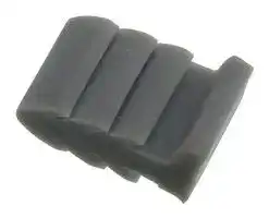
OJ2/J
JUMPER, TERMINAL BLOCK
⚠️ Reference pricing provided. In case of supply shortages, we will connect you with our trusted procurement partners to ensure your project's continuity.
- Manufacturer: EATON BUSSMANN
- Product type: Terminal Block Accessories
- For Use With: A2000 & LP2000 Series Terminal Blocks
- Product Range: OJ Series
- Accessory Type: Jumper
| Delivery and price | |
|---|---|
| Units per pack | 100 |
| Price | 0.331 € |
| Current stock | 10+ |
| Lead time | 30 days |
Datasheet

## **Connectors**

## **Section Contents**

**==> picture [250 x 505] intentionally omitted <==**

**----- Start of picture text -----**<br>
||||||||||||||||||||||||||||
|---|---|---|---|---|---|---|---|---|---|---|---|---|---|---|---|---|---|---|---|---|---|---|---|---|---|---|
|Page|
|Rail mount terminal blocks|
|NDN Series 35mm DIN rail mount blocks . . . . . . . .|304-305|
|N512-BK 12-Pole block . . . . . . . . . . . . . . . . . . . . . . . . . 306|
|NFT2-WH 2-Pole block . . . . . . . . . . . . . . . . . . . . . . . . .|306|
|NFT3-_ _ 3-pole block  . . . . . . . . . . . . . . . . . . . . . . . . . .306|
|NC3-WH 3-Pole block . . . . . . . . . . . . . . . . . . . . . . . . . .|307|
|NSE3-WH 3-Pole block . . . . . . . . . . . . . . . . . . . . . . . . .|307|
|NSS3-WH 3-Pole block . . . . . . . . . . . . . . . . . . . . . . . . . 307|
|Rail mount disconnect terminal blocks|
|15188 Series 3- and 4-Pole blocks  . . . . . . . . . . . . . . . . 308|
|15288 Series 3-Pole block  . . . . . . . . . . . . . . . . . . . . . .|308|
|Sectional terminal blocks|
|PLU3-_ _ 3-Pole block . . . . . . . . . . . . . . . . . . . . . . . . . .309|
|PLU1-WH 1- to 3-Pole block . . . . . . . . . . . . . . . . . . . . .|309|
|PSU1-WH 1- to 3-Pole block . . . . . . . . . . . . . . . . . . . . . 309|
|KT3-WH 3-Pole block . . . . . . . . . . . . . . . . . . . . . . . . . .|310|
|KT4-WH 4-Pole block . . . . . . . . . . . . . . . . . . . . . . . . . .|310|
|PLK-3_ _ 3-Pole block|. . . . . . . . . . . . . . . . . . . . . . . . .|310|
|Quick-connect terminal blocks|
|NTQ23-WH 3-Pole block . . . . . . . . . . . . . . . . . . . . . . . . 311|
|BNQ21-WH 1-Pole block . . . . . . . . . . . . . . . . . . . . . . . . 311|
|BQQ41-WH 1-Pole block . . . . . . . . . . . . . . . . . . . . . . . . 311|
|Double row terminal blocks|
|Series TB100 2- to 36-Pole blocks  . . . . . . . . . . . . . 312-313|
|Series TB200 & TB200HB 2- to 30-Pole blocks . . . .314-315|
|Series TB300 & TB345 2- to 24-Pole blocks  . . . . .|.298-299|
|Marking options and covers for double|
|row series  .|.|.|.|.|.|.|.|.|.|.|.|.|.|.|.|.|.|.|.|.|.|.|.|.|.|318|
|Top & bottom marking strips for double|
|row terminal blocks .|.|.|.|.|.|.|.|.|.|.|.|.|.|.|.|.|.|.|319|
|Series TB400 2- to 12-Pole double row|
|terminal blocks  . . . . . . . . . . . . . . . . . . . . . . . . .320|
|Series KU 2- to 12-Pole base mount double|
|row terminal blocks . . . . . . . . . . . . . . . . . . . . . . 321|
|Series TS finger-safe terminal blocks|
|2- to 12-Pole standard base . . . . . . . . . . . . . . . . . . . . .|322|
|2- to 12-Pole flat base . . . . . . . . . . . . . . . . . . . . . . . . . . 323|
|2- to 12-Pole raised base . . . . . . . . . . . . . . . . . . . . . . . .324|

**----- End of picture text -----**<br>


**==> picture [6 x 34] intentionally omitted <==**

**303**

**Connectors**

## **Rail Mount Terminal Blocks**

## **NDN Series**

## **Specifications**

**Description:** High-density, snap-on 35mm DIN rail compatible rail mount terminal blocks.

**Construction:** Unique, impact resistant, one-piece thermoplastic moldings. Heat treated stainless steel collars (to secure wires). Tin-plated copper alloy terminals. Zinc-plated steel screws.

**Circuits Per Foot:** Up to 48 circuits per foot. **Agency Information:** CE, UL E62622; CSA LR15364. **Flammability Rating:** UL 94V2

## **NDNV4-__ __(color)**

## **Specifications**

**Description:** Rail mount terminal block.

**Rating** :  NDNV4 30A, 600V **Center Spacing** :  0.25" (6.35mm) **Number of Poles** :  4 **Circuits Per Foot** :  48 **Circuit Jumper** :  JN4, 4 circuits **Wire Range** :  AWG #10-22 CU **Screw Size** :  #6-32

**Mounting Options** :  35mm DIN rail, C-rail

**Marking Tape** :  MTC6 **Torque Rating** :  18 lb-in

**Operating Temperature** :  105°C **Agency Information** :  UL File E62622, CSA File 15364 .

## **Catalog Numbers**

|**Catalog**||
|---|---|
|**Numbers**|**Colors**|
|NDNV4-WH|White (Standard)|
|NDNV4-BK|Black|
|NDNV4-YE|Yellow|


## **NDN3-__ __(color)**

## **Specifications**

**Description:** Rail mount terminal block.

**Rating** :  30A - field wiring:  40A - factory wiring 600V

**Center Spacing** :  0.300" (7.62mm) **Number of Poles** :  3 **Circuits Per Foot** :  38

**Circuit Jumper** :  JNDN3, 2 circuits **Wire Range** :  AWG #10-22 CU **Screw Size** :  #6-32

**Mounting Options** :  35mm DIN rail, C-rail

**Marking Tape** :  MT12-1-2 **Torque Rating** :  18 lb-in **Operating Temperature** :  105°C **Agency Information** :  UL File E62622, CSA File 15364.

## **Catalog Numbers**

|**Catalog**||
|---|---|
|**Numbers**|**Colors**|
|NDN3-WH|White (Standard)|
|NDN3-BK|Black|
|NDN3-BL|Blue|
|NDN3-RE|Red|
|NDN3-YE|Yellow|


## **NDN63-__ __(color)**

## **Specifications**

**Description:** Rail mount terminal block.

**Rating** :  65A, 600V **Center Spacing** :  0.375" (9.52mm) **Number of Poles** :  3 **Circuits Per Foot** :  30 **Circuit Jumper** :  JN3, 2 circuits **Wire Range** :  AWG #6-18 CU **Screw Size** :  #10-32

**Mounting Options** :  35mm DIN rail, C-rail

**Marking Tape** :  MT12-1-2 **Torque Rating** :  35 lb-in **Operating Temperature** :  105°C **Agency Information** :  UL File E62622, CSA File 15364.

## **Catalog Numbers**

**Catalog**

|**Catalog**||
|---|---|
|**Numbers**|**Colors**|
|NDN63-WH|White (Standard)|
|NDN63-BK|Black|
|NDN63-YE|Yellow|


For more information, visit www.cooperbussmann.com

**304**

**Connectors** ~~ee~~

## **Rail Mount Terminal Blocks**

## **NDN1-WH**

## **Specifications**

**Description:** Rail mount terminal block.

**Rating** :  90A, 600V **Center Spacing** :  0.635" (16.13mm)

**Number of Poles:** 1 **Circuits Per Foot** :  18

**Wire Range** :  AWG #2-18 Cu **Screw Size** :  #1/4-28

**Mounting Options** :  35mm DIN rail, C-rail

- Dove-tail option is available for mounting side-by-side. Order part no. NDN1A-WH

**Marking Tape** :  MT12-1-2

**Torque Rating** :  32 lb-in

**Operating Temperature** :  105°C **Agency Information** :  UL File E62622, CSA File 47235

## **Catalog Numbers**

|**Catalog**||
|---|---|
|**Number**|**Color**|
|NDN1-WH|White|


## **NDN111-__ __(color)**

## **Specifications**

**Description:** Rail mount terminal block.

**Rating** :  90A, 600V **Center Spacing** :  0.635" (16.13mm) **Number of Poles** :  3 **Circuits Per Foot** :  18

**Circuit Jumper** :  JN1, 2 circuits

- **Wire Range** :  AWG #2-18 Cu **Screw Size** :  #1/4-28

**Mounting Options** :  35mm DIN rail, C-rail, Base Mount

- Dove-tail option is available for mounting side-by-side. Order part no. NDN111-A

**Marking Tape** :  MT12-1-2

**Torque Rating** :  32 lb-in

**Operating Temperature** :  105°C **Agency Information** :  UL File E62622, CSA File 47235

## **Catalog Numbers**

|**Catalog**||
|---|---|
|**Numbers**|**Colors**|
|NDN111-WH|White (Standard)|
|NDN111-BK|Black|
|NDN111-BL|Blue|
|NDN111-RE|Red|
|NDN111-YE|Yellow|
|NDN111A-WH|White|
|NDN111A-BK|Black (Standard)|
|NDN111A-YE|Yellow|


## **NDN Series Terminal Block Accessories**

**NDNA NDNAS NFTA NRA SOA72 MARKING JUMPERS** 35mm DIN Rail 35mm DIN Rail C-Rail C-Rail 72" Long **TAPE** See Series Aluminum End Stop Aluminum Low Profile Stand-Off Channel See Series Specifications **NDNA 100** 1 meter Lengths to 72" No Flange For C-Rail Specifications **NDNA 200** 2 meters Aluminum Lengths to 37-1/2"

For more information, visit www.cooperbussmann.com

**305**

**Connectors**

## **Rail Mount Terminal Blocks**

## **N512-BK**

**Specifications Description:** Rail mount terminal block. **Rating** :  5A, 600V; 20A, 300V **Center Spacing** :  0.197" (5.00mm) **Number of Poles** :  12 **Circuits Per Foot** :  60 **Circuit Jumper** :  JN512, 12 circuits **Wire Range** :  AWG #12-22 Cu **Screw Size** :  #4-48

**Mounting Options** :  C-rail, 15mm DIN rail **Marking Tape** :  AT512 **Torque Rating** :  12 lb-in **Operating Temperature** :  105°C **Agency Information** :  CSA File 15364.

## **Catalog Numbers**

**Catalog Number Color** N512-BK Black

## **Dimensions - in (mm)**

**==> picture [139 x 116] intentionally omitted <==**

**----- Start of picture text -----**<br>
2.40<br>(60.96)<br>0.88<br>(22.35) CrHOHEHOHOH AE<br>1, eaggage<br>a<br>1.09<br>(27.68)<br>ae<br>**----- End of picture text -----**<br>


## **NFT2-__ __(color)**

**Specifications**

**Description:** Rail mount terminal block.

**Rating** :  40A, 600V; 55A Factory Wired

**Center Spacing** :  0.281" (7.13mm) **Number of Poles** :  2 **Circuits Per Foot** :  38 **Circuit Jumper** :  JN2, 2 circuits **Wire Range** :  AWG #8-22 Cu **Screw Size** :  #8-32 **Mounting Options** :  C-rail **Marking Tape** :  MT12-1-2 **Torque Rating** :  18 lb-in

**Operating Temperature** :  105°C **Agency Information** :  UL File E62622, CSA File 15364.

## **Catalog Numbers**

|**Catalog**<br>**Numbers**<br>NFT2-WH|**Colors**<br>White|
|---|---|
|NFT2-BK|Black|
|NFT2-BL|Blue|
|NFT2-RE|Red|


## **Dimensions - in (mm)**

**==> picture [146 x 128] intentionally omitted <==**

**----- Start of picture text -----**<br>
0 .6 0 0.07 1.29<br>(15.44) (1.78) (32.94)<br>0.93 0.36<br>(23.80) (9.14)<br>-+ f<br>1.68 1.23<br>(42.82) (31.34)<br>—<br>|<br>0 .65<br>(16.51)<br>:<br>**----- End of picture text -----**<br>


## **NFT3-__ __(color)**

**Specifications Description:** Rail mount terminal block.

**Rating** :  40A, 600V 55A Factory Wired

**Center Spacing** :  0.390" (9.91 mm) **Number of Poles** :  3 **Circuits Per Foot** :  28 **Circuit Jumper** :  JN3, 2 circuits **Wire Range** :  AWG #8-22 Cu **Screw Size** :  #8-32

**Mounting Options** :  C-rail **Marking Tape** :  MT12-1-2 **Torque Rating** :  18 lb-in **Operating Temperature** :  105°C **Agency Information** :  UL File E62622, CSA File 47235.

## **Catalog Numbers**

|**Catalog**<br>**Numbers**<br>NFT3-WH|**Colors**<br>White (Standard)|
|---|---|
|NFT3-BK|Black|
|NFT3-BL|Blue|
|NFT3-RE|Red|
|NFT3-YE|Yellow|


## **Dimensions - in (mm)**

**==> picture [139 x 55] intentionally omitted <==**

**----- Start of picture text -----**<br>
1.18 1.29<br>(29.97) (32.94)<br>1.23<br>(31.37)<br>i_14_Pl_]f<br>**----- End of picture text -----**<br>


For more information, visit www.cooperbussmann.com

**306**

**Connectors**

## **Rail Mount Terminal Blocks**

## **NC3-__ __(color)**

**Specifications Description:** Rail mount terminal block. **Rating** :  175A, 600V **Center Spacing** : 1.06" (26.92mm) **Number of Poles** :  3 **Circuits Per Foot** :  11 **Wire Range** :  2/0-#14 Cu/Al **Screw Size** :  5/16-24

**Mounting Options** :  C-rail, Base Mount **Marking Tape** :  MT12-1-2

**Torque Rating** :  45 lb-in **Operating Temperature** :  105°C **Agency Information** :  UL File E62622, CSA File 15364.

## **Catalog Numbers**

**Catalog Number Color** NC3-WH White NC3-BK Black

## **NSE3-WH**

**Specifications Description:** Rail mount terminal block. **Rating** :  115A, 600V

**Center Spacing** :  1.06" (26.92mm) **Number of Poles** :  3 **Circuits Per Foot** :  11

**Circuit Jumper** :  JNSE3, 2 circuits **Wire Range** :  For use with wire crimped to ring terminal

**Screw Size** :  #1/4-28

**Mounting Options** :  C-rail, Base Mount

**Marking Tape** :  MT12-1-2 **Torque Rating** :  32 lb-in

**Operating Temperature** :  105°C **Agency Information** :  UL File E62622, CSA File 15364.

## **Catalog Numbers**

**Catalog Number Color** NSE3-WH White

## **NSS3-__ __(color)**

**Specifications Description:** Rail mount terminal block. **Rating** :  30A, 600V **Center Spacing** :  0.385" (9.77mm)

**Number of Poles** :  3 **Circuits Per Foot** :  28

**Circuit Jumper** :  JNSS3, 2 circuits **Wire Range** :  For use with wire crimped to ring terminal **Screw Size** :  #6-32 **Mounting Options** :  C-rail **Marking Tape** :  MT12-1-2 **Torque Rating** :  12 lb-in

**Operating Temperature** :  105°C **Agency Information** :  UL File E62622, CSA File 15364.

## **Catalog Numbers**

|**Catalog**||
|---|---|
|**Number**<br>NSS3-WH|**Color**<br>White|
|NSS3-BK|Black|


## **Dimensions - in (mm)**

## **Dimensions - in (mm)**

## **Dimensions - in (mm)**

**==> picture [488 x 181] intentionally omitted <==**

**----- Start of picture text -----**<br>
1.25<br>(79.38)3.12 (44.45)1.75 (31.75)  1.24<br>0.250 x 0.190 (31.50)<br>mtg.  s lot s<br>Gee 1.75 I oe (44.45) 1.75  — _<br>iG (44.45) t o k WSm7 7.<br>Dae e laatL St SE O S mae alelel 1<br>1.25<br>(31.75)<br>1.25 0.250 x 0.190"<br>(31.75) mtg.  s lot s<br>(S EI S HI S} [SHOES 1.53  | ae<br>(38.86)<br>3.12<br>(79.24)<br>1.32<br>(33.73)<br>IPI. vl|<br>**----- End of picture text -----**<br>


For more information, visit www.cooperbussmann.com

**307**

**Connectors**

## **Rail Mount Disconnect Terminal Blocks**

## **15188 Series**

## **Specifications**

**Description:** Disconnect terminal blocks for 35mm DIN rail mount. **Rating** :  30A, 600V* **Center Spacing** :  0.375” (9.52mm)

**Wire Range** :  #12-16 AGW Cu **Screw Size** :  #6-32 zinc-plated philslot **Number of Poles** :  3- and 4-pole only **Mounting** :  35mm DIN Rail Optional End Stop NDNAS **Jumpers** :  2- through 4-pole available

**Materials** :  Molded Base:  UL rated 94V-2 thermoplastic. Tin plated copper alloy contacts.

**Torque Rating** :  12 lb-in

**Operating Temperature** :  105°C

**Agency Information** :  UL File E62622, CSA File 47235.

* 30A rating achieved with #10AWG wire crimped to ring terminal; 25A without.

## **Catalog Number Build-A-Code**

|Series||Poles|Poles|Wiring|Options|Options|Options|
|---|---|---|---|---|---|---|---|
|15188  –|15188  –|3 to 4<br>LJ||Blank = In-line<br>Oo|S = Locking Snap<br>5|||
|||||R = Reverse||||


**Dimensions - in (mm)** In-Line Wiring Direction

## **15288 Series**

**Specifications Description:** Disconnect terminal blocks for 35mm DIN rail Lit ¢ / mount. **Rating** :  65A, 600V* **Center Spacing** :  0.54” (13.7mm) **Wire Range** :  #6-16 AWG **Screw Size** :  #8-32 zinc-plated philslot **Number of Poles** :  3-pole only **Mounting** :  35mm DIN Rail **Optional Accessories** :  Optional End Stop NDNAS (order optional accessories seperately) **Materials** :  Molded Base:  UL rated 94V2 thermoplastic. Tin-plated copper alloy contacts.

**Torque Rating** :  20 lb-in (30 lb-in for 8AWG bare wire) **Operating Temperature** :  105°C (221°F) **Agency Information** :  UL File E62622

*CSA rating achieved with #6 AWG wire crimped to ring terminal 50A without.

## **Catalog Number Build-A-Code**

Series Poles Wiring Options** ~~Cn~~ 15288  – - ODoOoo 3 Blank = In-line S = Snap R = Reverse ST = Screw Together SS = Solid DIN Rail Snap

**Options can be combined, e.g. STSS

**==> picture [68 x 82] intentionally omitted <==**

**----- Start of picture text -----**<br>
3 Pole = 1.19 (30.22)<br>4 Pole = 1.56 (39.62)<br>ai 1.94<br>(49.27)<br>|<br>**----- End of picture text -----**<br>


## Reverse Wiring Direction

**==> picture [171 x 70] intentionally omitted <==**

**----- Start of picture text -----**<br>
3 Pole = 1.19 (30.22)<br>4 Pole = 1.56 (39.62)<br>0.375 0.22<br>| N —_ (9.52) | (5.58)<br>1.94<br>> a Gr (49.27)<br>**----- End of picture text -----**<br>


## **Dimensions - in (mm)**

Reverse Wiring Direction

**==> picture [95 x 9] intentionally omitted <==**

**----- Start of picture text -----**<br>
In-Line Wiring Direction<br>**----- End of picture text -----**<br>


**==> picture [72 x 203] intentionally omitted <==**

**----- Start of picture text -----**<br>
1.70<br>(43.2)<br>2.30<br>(58.4)<br>for  S T option<br>0.54<br>- (13.7) on —<br>F _<br>1.94<br>(49.27)<br>1.70<br>(43.2)<br>1.94 |<br>(49.27)<br>**----- End of picture text -----**<br>


For more information, visit www.cooperbussmann.com

**308**

**Connectors**

## **Sectional Terminal Blocks**

## **PSU1-WH**

## **PLU3-_ _(color)**

## **PLU1-WH**

**Specifications**

**Specifications** > **Description:** Depluggable rail mount sectional Ws Fe? terminal block. **Rating** :  70A, 600V **Center Spacing** :  0.625" (15.88mm) **Number of Poles** :  1-3 **Part Numbers** :

**Specifications Description:** Depluggable rail mount sectional terminal block. **Rating** :  45A*, 600V

**Description:** Depluggable rail mount sectional terminal block.

**Rating** :  40A, 600V **Center Spacing** :  0.390" (9.91mm) **Number of Poles** :  3 **Circuits Per Foot** :  28 **Circuit Jumper** :  JN3, 2 circuits **Wire Range** :  AWG #8-22 Cu **Screw Size** :  #8-32 **Mounting Options** :  C-rail, Stackable **Marking Tape** :  MT12-1-2 **Torque Rating** :  18 lb-in **Operating Temperature** :  105°C **Agency Information** :  UL File E62622, CSA File 15364.

*45A rating achieved with ring terminal crimped to wire.

**Center Spacing** :  0.625" (15.88 mm) **Number of Poles** :  1-3 **Part Number:**

- PLU1 (1-pole)

- PLU11 (2-pole)

   - PSU1 (1-pole)

- PLU111 (3-pole)

- PSU11 (2-pole)

- PSU111 (3-pole)

**Circuits Per Foot** :  19 **Circuit Jumper** :  JN1, 2 circuits **Wire Range** :  AWG #4-18 Cu **Screw Size** :  #1/4-28 **Mounting Options** :  C-rail, Stackable **Marking Tape** :  MT12-1-2 **Torque Rating** :  32 lb-in **Operating Temperature** :  105°C **Agency Information** :  UL File E62622, CSA File 15364.

**Circuits Per Foot** :  19

**Wire Range** :  For use with crimp on connectors only.

**Screw Size** :  #10-32

**Mounting Options** :  C-rail, Stackable **Marking Tape** :  MT12-1-2 **Torque Rating** :  24 lb-in

## **Catalog Numbers**

|**Catalog**<br>**Number**<br>PLU3-WH<br>PLU3-BK<br>PLU3-YE|**Color**<br>White (Standard)<br>Black<br>Yellow|White (Standard)|
|---|---|---|


**Operating Temperature** :  105°C **Agency Information** :  UL File E62622, CSA File 15364

## **Catalog Numbers**

|**Catalog**|||
|---|---|---|
|**Number**|**Poles**|**Color**|
|PLU1-WH|1|White|
|PLU11-WH|2|White|
|PLU111-WH|3|White|


## **Catalog Numbers**

|**Catalog**|||||
|---|---|---|---|---|
|**Number**|**Poles**|**Color**|||
|PSU1-WH|1|White|||
|PSU11-WH|2|White|||
|PSU111-WH|3|White|||
|**Dimensions - in (mm)**||**Dimensions - in (mm)**|**1.93**|**Connectors**|


## **Dimensions - in (mm)**

**Dimensions - in (mm)**

**==> picture [500 x 136] intentionally omitted <==**

**----- Start of picture text -----**<br>
1.25 1.85 1.93<br>(31.75) (46.99) (49.12)<br>1.87 1.48 0.625 1.48<br>(47.49) (37.59) (15.88) (37.64)<br>0.59 1.79<br>(14.98) (45.64)<br>1.25 1.25 1.85<br>(31.75) (31.75) (46.99)<br>2.44<br>(62.10)<br>1.25 1.30<br>ee (31.75) (11.10) 0.43 (33.00)<br>**----- End of picture text -----**<br>


For more information, visit www.cooperbussmann.com

**309**

**Connectors**

## **Sectional Terminal Blocks**

## **KT3-_ _(color)**

## **Specifications**

**Description:** Depluggable rail mount sectional terminal block.

**Rating** :  40A, 600V **Center Spacing** : 0.390" (9.91mm) **Number of Poles** :  3 **Circuits Per Foot** :  28 **Circuit Jumper** :  JN3, 2 circuits **Wire Range** :  AWG #8-22 Cu **Screw Size** :  #8-32

**Mounting Options** :  Base Mount, Stackable

**Marking Tape** :  MT12-1-2 **Torque Rating** :  18 lb-in

**Operating Temperature** :  105°C **Agency Information** :  UL File E62622, CSA File 15364

## **Catalog Numbers**

**Catalog**

**Number Color** KT3-WH White KT3-BK Black KT3-RE Red

## **KT4-_ _(color)**

## **Specifications**

**Description:** Depluggable rail mount sectional terminal block.

**Rating** :  30A, 600V

## **Center**

**Spacing** :  0.25" (6.35mm) **Number of Poles** :  4 **Part Number** :

- •KT4-WH-A

•KT4-WH-B

Note: When used in series must order A and B

**Circuits Per Foot** :  48

**Circuit Jumper** :  JN4, 4 circuits **Wire Range** :  AWG #10-22 Cu **Screw Size** :  #6-32

**Mounting Options** :  Base Mount Mounting screws recommended every 12 circuits

**Marking Tape** :  MTC6

**Torque Rating** :  18 lb-in

**Operating Temperature** :  105°C **Agency Information** :  UL File E62622, CSA File 15364

## **Catalog Numbers**

## **PLK3-WH**

## **Specifications**

**Description:** Depluggable rail mount sectional terminal block. **Rating** :  40A, 600V

## **Center**

**Spacing** :  0.39" (9.91mm)

**Number of Poles** :  3 **Circuits Per Foot** :  28

**Circuit Jumper** :  JN3, 2 circuits **Wire Range** :  AWG #8-22 Cu **Screw Size** :  #8-32

**Mounting Options** :  Base Mount, Stackable; End Piece (Part No. KAD)

is required for mounting. Mounting screws recommended every 15 circuits. **Marking Tape** :  MT12-1-2 **Torque Rating** :  18 lb-in **Operating Temperature** :  105°C **Agency Information** :  UL File E62622

## **Catalog Numbers**

**Catalog Number Color** PLK3-WH White

**Catalog Number Color** KT4-WH White KT4-BK Black

## **Dimensions - in (mm)**

## **Dimensions - in (mm)**

**==> picture [324 x 137] intentionally omitted <==**

**----- Start of picture text -----**<br>
1.87 1.25 0.25 0.98 0.37<br>(47.63) (31.75) (6.35) (24.99) (9.40)<br>alittle!<br>Ti e to n | |<br>1.22<br>(31.04)<br>0.62 1.26<br>#8  s crew clearance (15.88) (32.23)<br>KAD<br>end mtg.<br>adapter 1.25<br>(31.75)<br>2.34 1.25<br>as (59.51) (31.75) T I<br>c o l e 1.34<br>RE (34.04)<br>**----- End of picture text -----**<br>


## **Dimensions - in (mm)**

**==> picture [128 x 89] intentionally omitted <==**

**----- Start of picture text -----**<br>
1.46 0.56<br>(37.22) (14.22)<br>Ff<br>1.79<br>(45.52)<br>1.84<br>(46.86)<br>**----- End of picture text -----**<br>


For more information, visit www.cooperbussmann.com

**310**

**Connectors**

## **Quick-connect Terminal Blocks**

## **NTQ23-WH**

**Specifications Description:** Quick-connect terminal block.

**Rating** :  40A, 600V **Center Spacing** : 0.390" (9.91mm) **Number of Poles** :  3 **Circuits Per Foot** :  28

**Wire Range** :  AWG #8-22 Cu **Screw Size** :  #8-32 **Quick Connects** :  0.250” x 0.031”

**Mounting Options** :  C-rail **Marking Tape** :  MT12-1-2 **Torque Rating** :  18 lb-in **Operating Temperature** :  105°C .

## **Catalog Numbers**

**Catalog Number Color** NTQ23-WH White

## **Dimensions - in (mm)**

**==> picture [114 x 223] intentionally omitted <==**

**----- Start of picture text -----**<br>
1.25<br>(31.75) Y (ie<br>t Ieee<br>1.25<br>|<br>(31.75)<br>~~ _<br>_ ~<br>1.31<br>(33.32)<br>1.25<br>om (31.75)<br>**----- End of picture text -----**<br>


## **BNQ21-WH**

**Specifications Description:** Quickconnect terminal block.

**Rating** :  40A, 600V **Center Spacing** : 0.437" (11.10mm) **Number of Poles** :  1 **Circuits Per Foot** :  24

**Wire Range** :  AWG #8-22 Cu **Screw Size** :  #8-32

**Quick Connects** :  0 **.** 250" x 0.031" **Mounting Options** :  Base Mount Stackable; End Piece (Part No. BQE) is required for mounting. Mounting screws recommended every 8 circuits. **Torque Rating** :  18 lb-in

**Operating Temperature** :  105°C **Screw Size** :  #8-32 **Agency Information** :  UL File E62622, CSA File 15364

## **Catalog Numbers**

**Catalog Number Color** BNQ21-WH White

## **Dimensions - in (mm)**

**==> picture [150 x 237] intentionally omitted <==**

**----- Start of picture text -----**<br>
#BQE #8 mtg.<br>(end mtg. adaptor) s crew<br>JE<br>LHI IE<br>lp B<br>|<_——_____——. panees A<br>oe _y<br>0.56<br>(14.28)<br>1.47<br>(37.33)<br>1.41<br>a an (35.81)<br>**----- End of picture text -----**<br>


## **BQQ41-WH**

**Specifications Description:** Quick-connect terminal block. **Rating** :  30A, 600V

**Center Spacing** : 0.437" (11.10mm) **Number of Poles** :  1 **Circuits Per Foot** :  24

**Wire Range** :  For use with quickconnect terminals only.

**Quick Connects** :  0.250" x 0.031" **Mounting Options** :  Base Mount, Stackable; End Piece (Part No. BQE) is required for mounting. Mounting screws recommended every 8 circuits. **Operating Temperature** :  105°C **Agency Information** :  UL File E62622, CSA File 15364

## **Catalog Numbers**

**Catalog Number Color** BQQ41-WH White

**==> picture [174 x 254] intentionally omitted <==**

**----- Start of picture text -----**<br>
Dimensions - in (mm)<br>#BQE #8 mtg.<br>(end mtg. adaptor) s crew<br>AAA<br>elle (<br>lg B<br>L <____— an A a<br>a i 0.56<br>(14.28)<br>1.47<br>(37.33)<br>1.41<br>J (35.81)<br>Connectors<br>**----- End of picture text -----**<br>


For more information, visit www.cooperbussmann.com

**311**

**Connectors**

## **Double Row Terminal Blocks**

## **Series TB100**

## **Specifications**

**Description:** Double row terminal blocks. **Rating** :  30A, 300V*

**Center Spacing** :  0.375” or 3/8” (9.52mm) **Wire Range** :  #14 - 22 AWG Cu

**==> picture [48 x 8] intentionally omitted <==**

**----- Start of picture text -----**<br>
TB100-08<br>**----- End of picture text -----**<br>


**Screw Size** :  #6-32 philslot screws

**Torque Rating** :  9 lb-in.

**Distance Between Barriers** :  0.30”  (7.62mm)

**Mounting** :  #6 screws

**Operating Temperature** :  130°C (266°F) max., -40°C (-40°F) min.

**==> picture [62 x 8] intentionally omitted <==**

**----- Start of picture text -----**<br>
TB100-04SP<br>**----- End of picture text -----**<br>


**Materials** :  Molded base: Black, UL rated 94V0 thermoplastic

Terminal plating: Tin over brass;  Screws: Zinc-plated steel **Breakdown Voltage** :  3600V

**Agency Information** :  UL File E62622/CSA File 47235; IEC Compliance; CE Certified

* Max rating shown; some options may be rated lower, consult Cooper Bussmann.

## **Dimensions - in**

|**PolesA**<br>**B**|**PolesA**<br>**B**|**Poles**<br>**A**<br>**B**|
|---|---|---|
|**Poles A**<br>**B**|**Poles A**<br>**B**|**Poles**<br>**A**<br>**B**|
|02<br>1.40<br>1.12|14<br>5.90<br>5.62|26<br>10.40<br>10.12|
|03<br>1.78<br>1.50|15<br>6.28<br>6.00|27<br>10.78<br>10.50|
|04<br>2.16<br>1.88|16<br>6.66<br>6.38|28<br>11.16<br>10.88|
|05<br>2.53<br>2.25|17<br>7.03<br>6.75|29<br>11.53<br>11.25|
|06<br>2.90<br>2.62|18<br>7.40<br>7.12|30<br>11.90<br>11.62|
|07<br>3.28<br>3.00|19<br>7.78<br>7.50|31<br>12.28<br>12.00|
|08<br>3.66<br>3.38|20<br>8.16<br>7.88|32<br>12.66<br>12.38|
|09<br>4.03<br>3.75<br>10<br>4.40<br>4.12|21<br>8.53<br>8.25<br>22<br>8.90<br>8.62|33<br>13.03<br>12.75<br>34<br>13.40<br>13.12|
|10<br>4.40<br>4.12<br>11<br>4.78<br>4.50|22<br>8.90<br>8.62<br>23<br>9.28<br>9.00|34<br>13.40<br>13.12<br>35<br>13.78<br>13.50|
|12<br>5.16<br>4.88|24<br>9.66<br>9.38|36<br>14.16<br>13.88|
|13<br>5.53<br>5.25|25<br>10.03<br>9.75||


TB100- in (mm)

**==> picture [210 x 124] intentionally omitted <==**

**----- Start of picture text -----**<br>
A<br>0.14 0.14<br>B<br>(3.5) (3.5)<br>0.88<br>0.31 (7.9)<br>(22.3)<br>~~PERSSS RBs<br>el a le el el so ,<br>0.17 dia. ae 0.375(9.5) (7.6)0.30 tf<br>1 (4.3) aaa eae 0.41 4+<br>0.25 (6.3) (10.4)<br>__CBEBEBEBECH<br>**----- End of picture text -----**<br>


## **Catalog Number Build-A-Code**

Series Poles Screw Options Marking/Cover Hardware Options TB100 — oo ooo _ ~~—_~~ 02 to 36 Blank = Steel philslot, zinc-plated L1 to L6 Marking Strips (See page 318) QC1 to QC20 = Quick connects 00 = Screws shipped bulk Special Markings (See page 318) J101 = Flat slip-on jumper (2 position only) B = Brass philslot, nickel-plated Covers (See page 318) 0J2 = Over barrier jumpers BS = Brass Sems philslot, nickel-plated 0J4 = Over barrier jumpers SP = Steel Sems philslot, zinc-plated P = Steel Sems (P-style) ST = Stainless steel, philslot STR = Stainless steel, phillips (recess)

For more information, visit www.cooperbussmann.com

**312**

**Connectors**

## **Double Row Terminal Blocks**

## **Screw Options**

**==> picture [411 x 22] intentionally omitted <==**

**----- Start of picture text -----**<br>
B BS SP P ST STR<br>Brass Philslot Brass SEMS Steel SEMS Steel (SEMS) Stainless Steel Stainless Steel<br>Nickel-Plated Philslot Nickel-Plated Philslot Zinc-Plated (P-Style) Philslot Phillips (recess)<br>**----- End of picture text -----**<br>


## **Hardware Options**

**Quick Connects – Assembled:** Terminals 0.187” x 0.020”. Maximum current rating 13 amps. For other orientations, contact Cooper Bussmann.

**==> picture [358 x 103] intentionally omitted <==**

**----- Start of picture text -----**<br>
QC1 QC2 QC3 QC4 QC5 QC6 QC7<br>QC8 QC9 QC10 QC11 QC12 QC13<br>QC14 QC15 QC16 QC17 QC18 QC19 QC20<br>**----- End of picture text -----**<br>


**Quick Connects – Bulk:** minimum order per part number – 100 pieces.

**==> picture [322 x 63] intentionally omitted <==**

**----- Start of picture text -----**<br>
QC101 QC102 QC103<br>Flat – none QC 45° – none QC 90° – none<br>QC104 QC105 QC106 QC107 QC108 QC109<br>Flat – Flat Flat – QC 45° Flat – QC 90°QC 45° – QC 45° QC 45° – QC 90°QC 90° – QC 90°<br>**----- End of picture text -----**<br>


**Jumpers – Bulk:** minimum order per part number – 100 pieces. Contact Cooper Bussmann for jumper assembly.

**==> picture [203 x 16] intentionally omitted <==**

**----- Start of picture text -----**<br>
J101 OJ2 OJ4<br>Flat slip-on Slip-on over barrier Closed over barrier<br>**----- End of picture text -----**<br>


For more information, visit www.cooperbussmann.com

**313**

**Connectors**

## **Double Row Terminal Blocks**

## **Series TB200 & TB200HB**

## **Specifications**

**Description:** Double row terminal blocks. **Ratings:**

Volts: — 300V* (TB200) — 600V* (TB200HB)

Amps: — 30A*

**Center Spacing** :  0.437” or 7/16” (11.10mm) **Wire Range** :  #12 - 22 AWG Cu **Screw Size** :  #6-32 philslot screws

**Torque Rating** :  9 lb-in.

**Distance Between Barriers** :  0.353”  (8.97mm)

**Mounting** :  #6 screws

**==> picture [63 x 108] intentionally omitted <==**

**----- Start of picture text -----**<br>
TB200-10SP<br>©,<br>TB200HB-06<br>**----- End of picture text -----**<br>


**Operating Temperature** :  130°C (266°F) max., -40°C (-40°F) min.

**==> picture [501 x 284] intentionally omitted <==**

**----- Start of picture text -----**<br>
Materials :  Molded base: Black, UL rated 94V0  TB200 - in (mm)<br>thermoplastic A<br>Terminal plating: Tin over brass;  Screws: zinc-plated steel<br>0.16 0.16<br>Breakdown Voltage :  4800V (4.0) B (4.0)<br>Agency Information :  UL File E62622, CSA File 47235 & 0.44 (11.2) 1.12<br>15364; IEC Compliance; CE Certified (28.4)<br>* Max rating shown; some options may be rated lower - consult factory.<br>0.437 0.353<br>Dimensions - in 0.17 dia. (11.1) (8.9)<br>Poles A B Poles A B Poles A B (4.3)<br>02 1.63 1.31 12 6.00 5.68 22 10.37 10.06 0.56<br>03 2.07 1.75 oe 13 6.44 6.12 23 10.81 10.50 .31 (7.8) A feet— (14.2)<br>04 2.51 2.18 14 6.87 6.56 24 11.25 10.93 = a<br>05 2.94 2.62 15 7.31 7.00 25 11.68 11.37<br>TB200HB<br>06 3.38 3.06 Po 16 7.75 7.43 26 12.12 11.81<br>07 3.82 3.50 17 8.19 7.87 27 12.56 12.25 A<br>08 4.25 3.93 18 8.62 8.31 28 13.00 12.68<br>09 4.69 4.37 19 9.06 8.75 29 13.44 13.12 0.16 0.16<br>10 5.13 4.81 a 20 9.50 9.18 30 13.87 13.56 (4.0) | B (4.0)<br>11 5.57 5.25 21 9.94 9.62<br>1” = 25.4mm. — eee<br>0.44 (11.2) (22.8)0.90 (34.8)1.37<br>0.437 0.353<br>0.17 dia. a i e (11.1) (8.9) oT Fe 0.17 x 0.22  s lot s<br>(4.3) (4.3 x 5.6)<br>+<br>0.75<br>0.33 (8.4) Ldeebee= (19.0)<br>**----- End of picture text -----**<br>


## **Catalog Number Build-A-Code**

Series Poles Screw Options TB — ~~“aeesog0~~ 02 to 30 Blank = Steel philslot, zinc-plated ~~ooo~~ 200 = Standard 00 = Screws shipped bulk 200HB = High barrier B = Brass philslot, nickel-plated

Marking/Cover Hardware Options ~~oo~~ L1 to L6 Marking Strips (See page 318) ~~cooOo~~ QC1 to QC20 = Quick connects Special Markings (See page 318) J201 = Flat slip-on jumper (2 position only) Covers (See page 318) 0J3 = Over barrier jumpers

B = Brass philslot, nickel-plated BS = Brass Sems philslot, nickel-plated SP = Steel Sems philslot, zinc-plated P = Steel Sems (P-style) ST = Stainless steel, philslot SS = Stainless steel Sems, philslot STR = Stainless steel, phillips (recess)

- 0J5 = Over barrier jumpers 0J7 = Over barrier jumpers

For more information, visit www.cooperbussmann.com

**314**

**Connectors**

## **Double Row Terminal Blocks**

## **Screw Options**

**==> picture [443 x 24] intentionally omitted <==**

**----- Start of picture text -----**<br>
B BS SP P ST SS STR<br>Brass Philslot Brass SEMS Steel SEMS Steel SEMS Stainless Steel Stainless Steel Stainless Steel<br>Nickel-Plated Philslot Nickel-Plated Philslot Zinc-Plated (P-Style) Philslot SEMS Philslot Phillips (recess)<br>**----- End of picture text -----**<br>


## **Hardware Options**

**Quick Connects – Assembled:** Terminals 0.25” x 0.031”. Maximum current rating 20 amps. For other orientations, contact Cooper Bussmann.

**==> picture [356 x 108] intentionally omitted <==**

**----- Start of picture text -----**<br>
QC1 QC2 QC3 QC4 QC5 QC6 QC7<br>QC8 QC9 QC11 QC10 QC12 QC13<br>QC14 QC15 QC16 QC17 QC18 QC19 QC20<br>**----- End of picture text -----**<br>


**Quick Connects – Bulk:** minimum order per part no. – 100 pieces.

**==> picture [312 x 64] intentionally omitted <==**

**----- Start of picture text -----**<br>
QC201/J QC202/J QC203/J<br>QC 45° – none Flat – none QC 90° – none<br>QC204/J QC205/J QC206/J QC207/J QC208/J QC209/J<br>Flat – Flat Flat – QC 45° Flat – QC 90° QC 45° – QC 45° QC 45° – QC 90° QC 90° – QC 90°<br>**----- End of picture text -----**<br>


**Jumpers – Bulk:** minimum. order per part no. – 100 pieces. Contact Cooper Bussmann for jumper assembly.

**==> picture [290 x 21] intentionally omitted <==**

**----- Start of picture text -----**<br>
J201/J OJ3/J OJ5/J OJ7/J<br>Flat slip-on Slip-on over Closed over Closed over<br>(not available on TB200HB) barrier for TB200HB barrier for TB200HB barrier for TB200<br>**----- End of picture text -----**<br>


For more information, visit www.cooperbussmann.com

**315**

**Connectors**

## **Double Row Terminal Blocks**

## **Series TB300 & TB345**

## **Specifications**

**Description:** Double row terminal blocks. **Ratings:**

Volts: — 600V* Amps: — 30A* (TB300) — 45A (TB345) **Center Spacing** :  0.562” or 9/16” (14.28mm) **Wire Range** :  #8 - 22 AWG Cu **Screw Size** : TB300 –  #8-32 philslot screws TB345 –  #10-32 philslot screws **Torque Rating** :  #8 screws - 16 lb-in. ; #10 screws - 20 lb-in.

**==> picture [62 x 110] intentionally omitted <==**

**----- Start of picture text -----**<br>
TB300-08<br>TB345-06SP<br>**----- End of picture text -----**<br>


**Distance Between Barriers** :  0.41”  (10.5mm)

**Mounting** :  TB300 – #8 screws;  TB345 – #10 screws **Operating Temperature** :  130°C (266°F) max., -40°C (-40°F) min.

**Material** :  Molded base: Black, UL rated 94V0 thermoplastic Terminal plating: Tin over brass;  Screws: zinc-plated steel **Breakdown Voltage** :  7500V

**Agency Information** :  UL File E62622, CSA File 47235; IEC Compliance; CE Certified

* Max rating shown; some options may be rated lower - consult Cooper Bussmann.

|**Poles**<br>**A**<br>**B**|**Poles**<br>**A**<br>**B**|**Poles**<br>**A**<br>**B**|
|---|---|---|
|**Poles**<br>**A**<br>**B**<br>02<br>2.13<br>1.69|**Poles**<br>**A**<br>**B**<br>10<br>6.62<br>6.19|**Poles**<br>**A**<br>**B**<br>18<br>11.12<br>10.68|
|03<br>2.69<br>2.25<br>04<br>3.25<br>2.81|11<br>7.18<br>6.75<br>12<br>7.75<br>7.31|19<br>11.68<br>11.25<br>20<br>12.24<br>11.81|
|04<br>3.25<br>2.81<br>05<br>3.81<br>3.37|7.75<br>7.31<br>13<br>8.31<br>7.87|20<br>11.81<br>21<br>12.80<br>12.37|
|06<br>4.37<br>3.94<br>07<br>4.94<br>4.50|14<br>8.87<br>8.44<br>15<br>9.43<br>9.00|22<br>13.37<br>12.93<br>23<br>13.93<br>13.50|
|07<br>4.94<br>4.50|15<br>9.43<br>9.00|23<br>13.93<br>13.50|
|08<br>5.50<br>5.06|16<br>9.99<br>9.56|24<br>14.49<br>14.06|
|09<br>6.06<br>5.62|17<br>10.56<br>10.12||


## TB300 & TB345 - in (mm)

**==> picture [239 x 147] intentionally omitted <==**

**----- Start of picture text -----**<br>
 8-32 binding head  s crew - TB 300<br>10-32 binding head  s crew - TB 345<br>A<br>0.22<br>B<br>(5.6)<br>4 SSE SSSE ——T<br>0.90 1.33<br>0.50 (12.7) (22.8) (33.8)<br>0.56<br>(14.2) 0.56 0.412 0.21 x 0.25  s lot s<br>.21dia. aan (14.2) (10.4) J |. (5.3 x 6.3)<br>(5.3)<br>0.81<br>0.33 (8.4) (20.5)<br>= ==<br>**----- End of picture text -----**<br>


## **Catalog Number Build-A-Code**

|Series|Series||||||Poles|Poles|Poles||Screw Options|Screw Options|Screw Options|Screw Options|Screw Options||Marking/Cover|Marking/Cover|Marking/Cover|Marking/Cover||Hardware Options|Hardware Options|Hardware Options|Hardware Options|Hardware Options|Hardware Options|Hardware Options|Hardware Options|
|---|---|---|---|---|---|---|---|---|---|---|---|---|---|---|---|---|---|---|---|---|---|---|---|---|---|---|---|---|---|
|TB                      —<br>300 = 8-32 screw<br>OOO|||||||02 to 24<br>Blank = Steel philslot, zinc-plated<br>OO<br>OOO|||||||||L1 to L6 Marking Strips (pg 318)<br>OU|||||QC1 to QC20 = Quick connects (TB300 only)<br>OUOO||||||||QC1 to QC20 = Quick connects (TB300 only)|
|345 = 10-32 screw|||345 = 10-32 screw||||||||00 = Screws shipped bulk||||||Special Markings (pg 318)|||||J301 = Flat slip-on jumper|||J301 = Flat slip-on jumper||J301 = Flat slip-on jumper|||
||||||||||||B = Brass philslot, nickel-plated|B = Brass philslot, nickel-plated|||||Covers (pg 318)|||||0J6 = Over barrier jumper||0J6 = Over barrier jumper|||0J6 = Over barrier jumper|||
||||||||||||BS = Brass Sems philslot, nickel-plated|BS = Brass Sems philslot, nickel-plated||||||||||0J11 = Over barrier jumper|||0J11 = Over barrier jumper|||||
||||||||||||(TB300 only)|||(TB300 only)||||||||||||||||
||||||||||||SP = Steel Sems philslot, zinc-plated||||SP = Steel Sems philslot, zinc-plated|||||||||||||||
||||||||||||P = Steel Sems (P-style)|P = Steel Sems (P-style)||||||||||||||||||
||||||||||||ST = Stainless steel, philslot|||||||||||||||||||
||||||||||||STR = Stainless steel, phillips (recess)||STR = Stainless steel, phillips (recess)|||||||||||||||||


For more information, visit www.cooperbussmann.com

**316**

**Connectors**

## **Double Row Terminal Blocks**

## **Screw Options**

**==> picture [379 x 25] intentionally omitted <==**

**----- Start of picture text -----**<br>
B BS SP P ST STR<br>Brass Philslot Brass SEMS Steel SEMS Steel SEMS Stainless Steel Stainless Steel<br>Nickel-Plated Philslot Nickel-Plated Philslot Zinc-Plated (P-Style) Philslot Phillips (recess)<br>**----- End of picture text -----**<br>


## **Hardware Options**

**Quick Connects – Assembled:** TB300 only. Terminals 0.25” x 0.031”. Maximum current rating 20 amps. For other orientations, contact Cooper Bussmann.

**==> picture [356 x 108] intentionally omitted <==**

**----- Start of picture text -----**<br>
QC1 QC2 QC3 QC4 QC5 QC6 QC7<br>QC8 QC9 QC10 QC11 QC12 QC13<br>QC14 QC15 QC16 QC17 QC18 QC19 QC20<br>**----- End of picture text -----**<br>


**Quick Connects – Bulk:** (*TB300 only) minimum order per part number. – 100 pieces.

**==> picture [338 x 65] intentionally omitted <==**

**----- Start of picture text -----**<br>
QC201 QC202 QC203<br>Flat – none QC 45° – none QC 90° – none<br>QC204 QC205 QC206 QC207 QC208 QC209<br>Flat – Flat Flat – QC 45° Flat – QC 90° QC 45° – QC 45° QC 45° – QC 90° QC 90° – QC 90°<br>**----- End of picture text -----**<br>


**Jumpers – Bulk:** minimum order per part number – 100 pieces. Contact Cooper Bussmann for jumper assembly.

J301 OJ6 OJ11 Flat slip-on(TB300 only) Closed over barrier Slip-on over barrier

For more information, visit www.cooperbussmann.com

**317**

**Connectors**

## **Marking Options and Covers for Double Row Series**

## **Standard Marking**

Standard markings are applied directly to the side(s) of a block. Standard color is white. Standard height is 0.125 inches (3.17mm).

Note: Blocks marked on both sides require a different code for each side. Example Style L1 on one side of the block requires Style L2 on the other side to ensure common terminal marking. To order, add appropriate suffix (L1, L2, L3, L4, L5 and/or L6) to block catalog number in the proper sequence.

## **Special Marking**

Special markings are available at an additional charge for preparation. Production charges for setup, handling and marking are the same as for standard marking. Drawing(s) must be submitted to ensure accuracy of part required. Consult Cooper Bussmann for price and delivery.

Note: Marking is not available on TB400 Series

## **Covers**

Covers prevent personnel, screws and foreign items from contacting live terminals. Available in white or clear plastic. Two cover clips supplied with each cover. Cover width is 1.31 inches (33.3mm).

All covers must be ordered separately. Consult Cooper Bussmann for special legends.

Example: 10 position cover, white, TB100 Series, no legends = Catalog Number **X12010** .

**==> picture [252 x 196] intentionally omitted <==**

**----- Start of picture text -----**<br>
1   2   3 3   2   1<br>L1 L2 L3<br>L4 L5 L6<br>K MASTER 3AC G REDBLUBLK 3<br>OUTPUT 134 GND M 300VMAX<br>1 2 3<br>3 2 1<br>20A 4<br>INPUT 134 MB<br>1   2   3 3   2   1<br>5<br>A<br>**----- End of picture text -----**<br>


**==> picture [252 x 122] intentionally omitted <==**

## **Catalog Number Build-A-Code**

|Series|Cover Strip|Cover Strip|Cover Strip|Poles|Poles|High Barrier Option Only|High Barrier Option Only|Cover|Clips – Bulk|
|---|---|---|---|---|---|---|---|---|---|
|X||||||||Part Number<br>DD1-J<br>– TB100 Series||
||120-  TB100/white|||02|to36(TB100)|HB = High Barrier||DD2-J|– TB200 Series|
||119-  TB100/clear|||02|to30(TB200/TB200HB)|||DD2HB-J –TB200HB Series||
||220-  TB200/TB200HB - white|||02|to24(TB300/TB345)|Example: 10 position cover, white,||DD3-J|– TB300 Series|
||219-  TB200/TB200HB - clear|||||TB100 Series, no legends . . .||||
||320-  TB300 & TB345 - white|||||Part number is X12010.||||
||319-  TB300 & TB345 - clear|||||||||


Note: Covers are not available on TB400 Series.

For more information, visit www.cooperbussmann.com

**318**

**Connectors**

## **Top & Bottom Marking Strips for Double Row Terminal Blocks**

**==> picture [252 x 126] intentionally omitted <==**

## **Top Marker Strips**

Top mounting marker strips are available in white (opaque) plastic. Two cover clips are supplied with each marker strip.

All top marker strips must be ordered separately. Consult factory for special legends.

Example: 12 position cover, TB200, 0.032” x 0.312”, with no legends = Catalog Number **X20312** .

Example: 12 position cover, TB200HB, 0.06” x 0.50”, with no legends = Catalog Number **X23312HB** .

## **Catalog Number Build-A-Code**

## High Barrier Option Only

Series Top Marker Strip

Poles 02 to 36 (TB100) HB = High Barrier 02 to 30 (TB200/TB200HB) 02 to 24 (TB300/TB345)

X 133 - TB100 (0.060 thk x 0.500 w) 103 - TB100 (0.032 thk x 0.312 w) 233 - TB200 (0.060 thk x 0.500 w) 233TB - TB200HB (0.060 thk x 0.500 w) 203 - TB200 (0.032 thk x 0.312 w) 203HB - TB200HB (0.032 thk x 0.312 w) 333 - TB300 & TB345 (0.060 thk x 0.500 w) 303 - TB300 & TB345 (0.032 thk x 0.380 w) Note: Marking Strips are not available on TB400 Series

Example: 12 position cover, TB200HB, 0.060˝ x 0.500˝, with no legends... Part No. is X23312HB.

## **Bottom Marker Strips**

Bottom mounting marker strips are made of black PVC, 0.030” thick. Space is available to handle most marking situations. All marker strips must be ordered separately.

To order, specify part number, required legends and (BF) bottom forward, (BR) bottom reverse, (TF) top forward, or (TR) top reverse. Consult factory for specials.

Example: 13 position strip, TB100 with no legends, space for marking one side = Catalog Number **X10513** .

Position for legends (one side, two sides) can be specified standard. Standard legend height is 0.125”. Standard leg-ends are 0-99 and A-Z. Special legends are available on special order. Drawing(s) must be submitted to ensure accuracy of part required.

**==> picture [252 x 119] intentionally omitted <==**

**----- Start of picture text -----**<br>
Space for marking one side Space for marking two sides<br>**----- End of picture text -----**<br>


## **Dimensions (in)**

|**Dim.**|**TB100**|**TB200**|**TB200HB **|**TB300**|**TB345**|**TB400**|
|---|---|---|---|---|---|---|
|A|1.13|1.37|1.62|1.58|1.58|N/A|
|B|1.38|1.62|1.81|1.81|1.81|N/A|


## **Catalog Number Build-A-Code**

Series Bottom Marker Strip Poles High Barrier Option Only Orientation X 105 = TB100/marking one side 02 to 36 (TB100) HB = High Barrier BF = Bottom forward 101 = TB100/marking both sides 02 to 30 (TB200/TB200HB) BR = Bottom reverse 205 = TB200/marking one side 02 to 24 (TB300/TB345) TF = Top forward 201 = TB200/marking both sides TR = Top reverse 295 = TB200HB/marking one side 291 = TB200HB/marking both sides 305 = TB300 & TB345/marking one side 301 = TB300 & TB345/marking both sides Note: Marking Strips are not available on TB400 Series.

For more information, visit www.cooperbussmann.com

**319**

**Connectors**

## **Double Row Terminal Blocks**

## **Series TB400**

## **Specifications**

**Description:** Double row terminal blocks. **Ratings:** Volts: — 600V Amps: — 75A **Center Spacing** :  0.687” or 11/16” (17.45mm) **Wire Range** :  #6-14 AWG Cu **Screw Size** :  #10-32 philslot screws **Torque Rating** :  20 lb-in. **Distance Between Barriers** :  0.56”  (14.3mm) **Mounting** :  #10 screws **Operating Temperature** :  130°C (266°F) max., -40°C (-40°F) min.

**Material** :  Molded base: Black, UL rated 94V0 thermoplastic Terminal plating:  Tin over brass;  Screws: zinc-plated steel **Breakdown Voltage** :  7500V

**Agency Information** :  UL File E62622, CSA File 47235; IEC Compliance; CE Certified

**Dimensions - in Poles A B Poles A B Poles A B** 02 2.51 2.06 06 5.26 4.81 10 8.01 7.56 03 3.20 2.75 07 5.95 5.50 11 8.70 8.25 04 3.89 3.44 08 6.64 6.19 12 9.39 8.94 ~~———~~ 05 4.58 4.13 09 7.33 6.88 1” = 25.4mm.

**Screw Options**

**==> picture [48 x 8] intentionally omitted <==**

**----- Start of picture text -----**<br>
TB400-05<br>**----- End of picture text -----**<br>


TB400 - in (mm)

**==> picture [223 x 161] intentionally omitted <==**

**----- Start of picture text -----**<br>
A<br>B<br>0.22<br>(5.6)<br>0.15 dia.<br>(3.8)<br>0.625 1.12<br>(15.9) (28.4)<br>eee<br>2 18 ee aya<br>0.22 dia. (5.6)<br>0.68 7 a 0.687 0.562<br>(17.4) (17.4) (14.3)<br>1.81<br>(46.0)<br>[TT<br>7 0.76<br>0.46 (11.7) (19.3)<br>1.34<br>(34.0)<br>" —<br>**----- End of picture text -----**<br>


B ST STR Brass Philslot Stainless Steel Stainless Steel Nickel-Plated Philslot Phillips (recess)

**Hardware Options**

OJ14: Closed over barrier

**Catalog Number Build-A-Code** Series Poles Screw Options Marking Hardware Options TB400  – ~~— oo~~ 02 to 12 Blank = Steel philslot, zinc-plated 0g00 Not available 0J14† - Jumper over barrier 00 = Screws shipped bulk B = Brass philslot, nickel-plated ST = Stainless steel, philslot STR = Stainless steel, phillips (recess)

†Contact factory for pole configuration.

For more information, visit www.cooperbussmann.com

**320**

**Connectors**

## **Base Mount Double Row Terminal Blocks**

## **Series KU**

## **Specifications**

**Description:** Base mount double row terminal blocks. **Ratings:**

Volts:— 600V Amps:— 60A*

**Center Spacing** : 0.625” (15.88mm) **Number of Poles** :  2- to 12-poles **Wire Range** :  #6-22 AWG Cu

**Screw Size:** #10-32 **Torque Rating:** 20 lb-in. **Distance Between Barriers:** 0.437”  (11.09mm)

**Mounting** :  Base mount

**Material** :  Molded base:  Black, UL rated 94V1 Nuclear Grade Noryl Terminal plating:  Nickel over brass

## Series KU - in (mm)

**B** Terminal plating:  Nickel over brass **0.62 Operating Temperature** :  105°C max. **(15.9) Agency Information** :  UL File E62622, CSA File 47235 * 60A rating achieved with #6 copper wire crimped to ring terminal. **Dimensions - in** -4€—-»J- - ef} - - et -- I] -- FED **(50.8)2.00 (38.1)1.50 KU KUX Only #10 s crew Poles A B A clearance** 02 2.50 1.62 2.00 03 3.12 2.25 2.62 ~~OO~~ **1.2** ~~**5** = CO~~ 04 3.75 2.87 3.25 **0.43 (31.8) (11.1)** 05 4.37 3.50 3.87 ~~CO~~ 06 5.00 4.12 4.50 ~~|~~ **0.50** 07 5.62 4.75 5.12 **(12.7)** 08 6.25 5.37 5.75 09 6.87 6.00 6.37 ~~OO~~ 10 7.50 6.62 7.00 ~~ese~~ 11 8.12 7.25 7.62 **A** 12 8.75 7.87 8.25 ~~OO~~ 1” = 25.4mm. ~~ee~~

## **Catalog Number Build-A-Code**

Series Poles Screw Options Covers Marking Strip – Oooo OO oo no foo KU = Standard block 02 to 12 00 = Screws shipped bulk WC = Top cover & MT = Matte finish KUH = Block W = Brass washer head, 2 end plates NU = Numbered 1 to 12, horizontal KUX = Short block nickel-plated NUV = Numbered 1 to 12, vertical KURL = Standard w/removable link P = Steel screw w/pressure plate PT = Marker strip for cover KUXRL = Short block w/removable link zinc-plated B = Brass washer head, no plating BP = Brass philslot, nickel-plated **Catalog Number - SC Series** KUSC = Standard w/shorting strap 02 to 12 00 = Screws shipped bulk WC = Top cover & PT* = Marker strip for cover & 4 shorting screws W = Brass washer head, 2 end plates KUXSC = Short block w/shorting strap nickel-plated & 4 Shorting screws P = Steel screw w/pressure plate zinc-plated B = Brass washer head, no plating BP = Brass philslot, nickel-plated *Requires WC cover option

## **Accessories**

MTMU## Molded Marking Tape Matte Finish

NUM## Molded Marking Tape

**==> picture [29 x 20] intentionally omitted <==**

**----- Start of picture text -----**<br>
JU12<br>Jumper<br>12 Circuits<br>**----- End of picture text -----**<br>


NUE NUC## End Piece for NUC Cover

For more information, visit www.cooperbussmann.com

**321**

**Connectors**

## **Standard Base Terminal Blocks**

## **Series TS — 8.0, 10.0, 12.0, 13.5mm centers**

## **Specifications**

**Description:** 8, 10, 12 and 13.5mm center, standard base terminal blocks.

**Construction:** Mold to length polyamide type 6/6 housing, nickel-plated brass contacts and stainless steel wire protector.

## **Ratings:**

Volts: — 600V Amps: — 20A (TS08)

- 30A (TS10)

- 35A (TS12)

- 50A (TS14)

**Wire Range** :  See Specifications Table

**Housing Material** :  Polyamide Type 6/6, 94V2 (white) **Contact Material** :  Nickel-Plated Brass

**Wire Protector** :  Stainless Steel

**Screw Size** : See Specifications Table

**Operating Temperature** :  105°C (221°F) max., -30°C (-22°F) min.

**Torque Rating** :  See Specifications Table

|**Torque Rating**:  See Specifications Table|**Torque Rating**:  See Specifications Table|**Torque Rating**:  See Specifications Table|
|---|---|---|
|**Torque Rating**:  See Specifications Table<br>**Agency Information**:  UL File E62622; CE Certified<br>**A Dimensions - in (mm)**<br>**Poles**<br>**TS08**<br>**TS10**<br>**TS12**<br>**TS14**<br>2<br>0.622 (15.8)<br>0.689 (17.5)<br>0.815 (20.7)<br>0.906 (23.0)<br>3<br>0.937 (23.8)<br>1.083 (27.5)<br>1.287 (32.7)<br>1.437 (36.5)<br>4<br>1.252 (31.8)<br>1.476 (37.5)<br>1.760 (44.7)<br>1.969 (50.0)<br>~~re~~|||
|5<br>1.567 (39.8)<br>1.870 (47.5)<br>6<br>1.882 (47.8)<br>2.264 (57.5)|2.232 (56.7)<br>2.705 (68.7)|2.500 (63.5)<br>3.031 (77.0)|
|7<br>2.232 (55.8)<br>2.657 (67.5)|3.177 (80.7)|3.563 (90.5)|
|8<br>2.512 (63.8)<br>3.051 (77.5)|3.650 (92.7)|4.094 (104.0)|
|9<br>2.827 (71.8)<br>3.445 (87.5)|4.122 (104.7)|4.626 (117.5)|
|10<br>3.142 (79.8)<br>3.839 (97.5)|4.594 (116.7)|5.157 (131.0)|
|11<br>3.457 (87.8)<br>4.232 (107.5)|5.067 (128.7)|5.689 (144.5)|
|12<br>3.772 (95.8)<br>4.626 (117.5)|5.539 (140.7)|6.220 (158.0)|


**==> picture [212 x 183] intentionally omitted <==**

**----- Start of picture text -----**<br>
E<br>C<br>fh<br>B<br>D<br>ae Pa n A ne<br>D D<br>1.2mm<br>STANDOFF<br>o oh mm<br>F F F<br>WIRE PROTECTOR<br>**----- End of picture text -----**<br>


|**Specifications**<br>**Torque**|**Specifications**<br>**Torque**|**Clamping**|**Wire Range**|**Dimensions - in (mm)**|**Dimensions - in (mm)**|||||
|---|---|---|---|---|---|---|---|---|---|
|**Position**|**in-lb**|**Area (mm2)**|**AWG (Cu)**|**Screw**|**B**|**C**|**D**|**E**|**F**|
|TS0801|3.5|4.0|22-12 Sol./Str.|M2.6x5|0.67 (17.0)|0.57 (14.5)|0.32 (8.0)|0.11 (2.9)|0.11 (2.8±0.1)|
|TS0802|3.5|1.5|22-12 Sol./Str|M2.6x5|0.67 (17.0)|0.57 (14.5)|0.32 (8.0)|0.11 (2.9)|0.11 (2.8±0.1)|
|TS1001|4.4|6.0|22-10 Sol., 14-10 Str.|M3.0x6|0.80 (20.2)|0.67 (17.0)|0.39 (10.0)|0.14 (3.6)|0.13 (3.4±0.1)|
|TS1002|4.4|2.5|22-12 Sol./Str, 10 Sol.|M3.0x6|0.80 (20.2)|0.67 (17.0)|0.39 (10.0)|0.14 (3.6)|0.13 (3.4±0.1)|
|TS1201|7.0|10.0|22-10 Sol./Str.|M3.5x7|0.94 (23.8)|0.75 (19.0)|0.47 (12.0)|0.14 (3.9)|0.15 (4.2±0.1)|
|TS1202|7.0|6.0|22-10 Sol./Str.|M3.5x7|0.94 (23.8)|0.75 (19.0)|0.47 (12.0)|0.15 (3.9)|0.15 (4.2±0.1)|
|TS1401|12.0|16.0|20-8 Sol./Str.|M4.0x9|1.01 (25.6)|0.99 (25.2)|0.53 (13.5)|0.17 (4.4)|0.19 (5.0±0.1)|
|TS1402|12.0|10.0|20-8 Sol./Str.|M4.0x9|1.01 (25.6)|0.99 (25.2)|0.53 (13.5)|0.17 (4.4)|0.19 (5.0±0.1)|


## **Catalog Number Build-A-Code**

Series Base Poles ~~oo...~~ TS ~~Oo~~ »xooF ~ 08 = 20A 01 = Standard 02 to 12 10 = 30A 02 = Standard w/ wire protector 12 = 35A 14 = 50A

For more information, visit www.cooperbussmann.com

**322**

**Connectors**

## **Flat Base Terminal Blocks**

## **Series TS — 8.0, 10.0mm centers**

## **Specifications**

**Description:** 8 and 10mm center, flat base terminal blocks. **Construction:** Mold to length polyamide type 6/6 housing, nickel-plated brass contact and stainless steel wire protector. **Ratings:**

Volts: — 600V Amps: — 20A (TS08) — 30A (TS10)

**Wire Range** :  See Specification Table **Housing Material** :  Polyamide Type 6/6, 94V2 (white) **Contact Material** :  Nickel-Plated Brass

**Wire Protector** :  Stainless Steel **Screw Size** : See Specification Table **Operating Temperature** :  105°C (221°F) max., -30°C (-22°F) min.

**Torque Rating** :  See Specification Table **Agency Information** :  UL File E62622; CE Certified

**A Dimensions - in (mm)**

|**Poles**<br>2|**TS08**<br>0.622 (15.8)|0.622 (15.8)|**TS10**<br>0.689 (17.5)|0.689 (17.5)|
|---|---|---|---|---|
|3|0.937 (23.8)|0.937 (23.8)|1.083 (27.5)|1.083 (27.5)|
|4<br>5|1.252 (31.8)<br>1.567 (39.8)|1.252 (31.8)<br>1.567 (39.8)|1.476 (37.5)<br>1.870 (47.5)|1.476 (37.5)<br>1.870 (47.5)|
|6|1.882 (47.8)|1.882 (47.8)|2.264 (57.5)|2.264 (57.5)|
|7|2.232 (55.8)|2.232 (55.8)|2.657 (67.5)|2.657 (67.5)|
|8|2.512 (63.8)|2.512 (63.8)|3.051 (77.5)|3.051 (77.5)|
|9|2.827 (71.8)|2.827 (71.8)|3.445 (87.5)|3.445 (87.5)|
|10|3.142 (79.8)|3.142 (79.8)|3.839 (97.5)|3.839 (97.5)|
|11<br>12|3.457 (87.8)<br>3.772 (95.8)|3.457 (87.8)<br>3.772 (95.8)|4.232 (107.5)<br>4.626 (117.5)|4.232 (107.5)<br>4.626 (117.5)|


**==> picture [171 x 179] intentionally omitted <==**

**----- Start of picture text -----**<br>
E<br>C<br>HZ _<br>oy<br>B<br>D<br>A<br>D D<br>F F<br>WIRE PROTECTOR<br>**----- End of picture text -----**<br>


## **Specifications**

||**Torque**|**Clamping**|**Wire Range**|**Dimensions - in (mm)**|**Dimensions - in (mm)**|||||
|---|---|---|---|---|---|---|---|---|---|
|**Position**|**in-lb**|**Area (mm2)**|**AWG (Cu)**|**Screw**|**B**|**C**|**D**|**E**|**F**|
|TS0803|3.5|4.0|22-12 Sol./Str.|M2.6x5|0.64 (16.3)|0.53 (13.3)|0.32 (8.0)|0.11 (2.9)|0.11 (2.8±0.1)|
|TS0804|3.5|1.5|22-12 Sol./Str|M2.6x5|0.64 (16.3)|0.52 (13.3)|0.32 (8.0)|0.11 (2.9)|0.11 (2.8±0.1)|
|TS1003|4.4|6.0|22-10 Sol., 14-10 Str.|M3.0x6|0.80 (20.2)|0.62 (15.8)|0.39 (10.0)|0.14 (3.6)|0.13 (3.2±0.1)|
|TS1004|4.4|2.5|22-12 Sol./Str., 10 Sol.|M3.0x6|0.80 (20.2)|0.62 (15.8)|0.39 (10.0)|0.14 (3.6)|0.13 (3.2±0.1)|


## **Catalog Number Build-A-Code**

Series Base Poles TS (JU LIL) LIU 08 = 20A 03 = Flat 02 to 12 10 = 30A 04 = Flat w/ wire protector

For more information, visit www.cooperbussmann.com

**323**

**Connectors**

## **Raised Base Terminal Blocks**

## **Series TS - 8.0, 10.0mm centers**

## **Specifications**

**Description:** 8 and 10mm center, raised base terminal blocks.

**Construction:** Mold to length polyamide type 6/6 housing, nickel-plated brass contacts and stainless steel wire protector.

**Ratings:**

Volts: — 600V

Amps: — 20A (TS08)

— 30A (TS10)

**Wire Range** :  See Table

**Housing Material** :  Polyamide Type 6/6, 94V2 (white) **Contact Material** :  Nickel-plated Brass

**==> picture [126 x 7] intentionally omitted <==**

**----- Start of picture text -----**<br>
Note: TS Series standard base pictured above.<br>**----- End of picture text -----**<br>


**Wire Protector** :  Stainless Steel **Screw Size** : See Table

**==> picture [481 x 181] intentionally omitted <==**

**----- Start of picture text -----**<br>
|||||||
|---|---|---|---|---|---|
|E|
|Operating Temperature|:  105°C (221°F) max.,|
|-30°C (-22°F) min.|
|Torque Rating|:  See Table|C|
|Agency Information|:  UL File E62622; CE Certified|
|A Dimensions|
|Poles|TS08|TS10|oe|D|
|B|
|2|0.622 (15.8)|0.689 (17.5)|A|
|3|0.937 (23.8)|1.083 (27.5)|
|4|1.252 (31.8)|1.476 (37.5)|D|D|
|5|1.567 (39.8)|1.870 (47.5)|
|6|1.882 (47.8)|2.264 (57.5)|
|7|2.232 (55.8)|2.657 (67.5)|4.3mm|ag|oo|
|8|2.512 (63.8)|3.051 (77.5)|
|9|2.827 (71.8)|3.445 (87.5)|
|10|3.142 (79.8)|3.839 (97.5)|
|11|3.457 (87.8)|4.232 (107.5)|
|F|F|
|re|12|3.772 (95.8)|4.626 (117.5)|~|
|WIRE PROTECTOR|

**----- End of picture text -----**<br>


## **Specifications**

**==> picture [512 x 50] intentionally omitted <==**

**----- Start of picture text -----**<br>
|||||||||||||
|---|---|---|---|---|---|---|---|---|---|---|---|
|Torque|Clamping|Wire Range|Dimensions - in (mm)|
|Position|in-lb|Area (mm|[2]|)|AWG (Cu)|Screw|B|C|D|E|F|
|TS0805|3.5|4.0|22-12 Sol./Str.|M2.6x5|0.64 (16.30)|0.67 (16.90)|0.32 (8.00)|0.11 (2.90)|0.11 (2.8±0.1)|
|TS0806|3.5|1.5|22-12 Sol./Str|M2.6x5|0.64 (16.30)|0.67 (16.90)|0.32 (8.00)|0.11 (2.90)|0.11 (2.8±0.1)|
|TS1005|4.4|6.0|22-10 Sol., 14-10 Str.|M3.0x6|0.80 (20.20)|0.79 (20.10)|0.39 (10.00)|0.14 (3.60)|0.13 (3.2±0.1)|
|TS1006|4.4|2.5|22-12 Sol./Str., 10 Sol.|M3.0x6|0.80 (20.20)|0.79 (20.10)|0.39 (10.00)|0.14 (3.60)|0.13 (3.2±0.1)|

**----- End of picture text -----**<br>


## **Catalog Number Build-A-Code**

Series Base Poles TS ~~—oo0C UO—i~~ 08 = 20A 05 = Raised 02 to 12 10 = 30A 06 = Raised w/ wire protector

For more information, visit www.cooperbussmann.com

**324**
Updated at February 9, 2023
About Novapart
Novapart is a B2B electronic component broker specialising in stock shortages and cost reduction. We source hard-to-find parts and identify compliant alternatives across a catalogue of 410,000+ components from 500+ manufacturers.
Learn more →Stock Shortage Specialist
When a component is unavailable, discontinued or has an unacceptable lead time, we tap into our network of vetted European and Asian distributors to source what you need — without compromising on quality or traceability.
Request a quote →Compliant Alternatives
We identify pin-to-pin, electrically equivalent substitutes that meet the same certifications (RoHS, AEC-Q100, REACH) as your original specification — validated against datasheets, not just part numbers. Often at a lower cost.
BOM Analysis service →