
Image not available
Illustrative purposes only

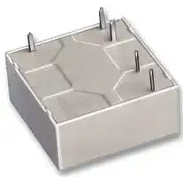
OB 5693.11/9005L1 DC 24V
General Purpose Relay, OB 5693 Series, Power, Latching Single Coil, SPST-NC, 24 VDC, 16 A
⚠️ Reference pricing provided. In case of supply shortages, we will connect you with our trusted procurement partners to ensure your project's continuity.
- Manufacturer: DOLD
- Product type: Power Relays
- Contact Configuration:SPST-NC; Coil Voltage:24VDC; Contact Current:16A; Product Range:OB 5693 Series; Relay Mounting:Through Hole; Coil Type:Latching Single Coil; Contact Voltage VAC:250VAC;
- Coil Type: Latching Single Coil
- Coil Voltage: 24VDC
- Product Range: -
- Relay Mounting: Through Hole
- Coil Resistance: 575ohm
- Contact Current: 16A
- Relay Terminals: Solder
- Contact Material: Silver Tin Oxide
- Contact Voltage VAC: 250VAC
- Contact Voltage VDC: -
- Contact Configuration: SPST-NC
| Delivery and price | |
|---|---|
| Units per pack | 50 |
| Price | 12.57 € |
| Current stock | 10+ |
| Lead time | 30 days |
Datasheet

## **Printed circuit board relay,** bistable OB 5693, OB 5694

- according to IEC/EN 60 669-1

- OB 5693: horizontal model OB 5694: vertical model

- bistable, mechanical latching of contact

- same pulse (energy and direction) for both switching positions

- safe separation according to IEC/EN 61 140, IEC/EN 60 335

- AC and DC - model

- Patent on function principle

- on request wash proof

- switching reliability acc. to IEC/EN 60 669-2-2

## **Applications**

- Remote switch

- Switching of sockets

## **Technical data**

Relay type

## 1. 0 **Relay coil**

**==> picture [498 x 291] intentionally omitted <==**

**----- Start of picture text -----**<br>
|||||||||
|---|---|---|---|---|---|---|---|
|1.|1|Nominal voltage|AC V|12, 24, 42, 230|50/60 Hz|
|DC V|6, 12, 15, 24, 48, 60, 110|
|1.|2|Nominal consumption|W/VA|1 / 1,4|
|2.|0|Contacts|
|2.|1|Contact arrangement|1 changeover contact or 1 NO|
|2.|2|Contact material|AgNi 10, AgSnO2|
|2.|3|Rated insulation voltage|AC V|250|
|Switching voltage min./max.|AC V|10 / 400|
|2.|4|Limiting continuous current Ith|A|16|
|Switching current min./max.|A|10 mA|[1)]|/ 50 (20 ms)|
|2.|5|Switching power min./max.|VA|3 / 4000|
|Switching power min./max.|W|35 / 300|
|Incandescent lamp load|W|1500|
|2.|7|Electrical life|at 1 s On ; 1 s Off|
|at AC 250 V 16 A cos ϕ = 1    switching cycles|≥ 5 x 10|[4]|
|2.|8|max. switching frequency       switching cycles/s|5|
|2.10|Contact force|cN|≥ 8|
|2.14|Contact gap|mm|≥ 0,5|
|3.|0|Other|
|3.|1|Mechanical life|switching cycles|DC ≥ 10 x 10|[6 ]|, AC ≥ 1 x 10|[5]|
|3.|2|Temperature range|°C|- 40 ... + 50|
|3.|3|Degree of protection|IP 40, optionally IP 67    IEC/EN 60 529|
|3.|4|Housing material|PA and PBT|
|3.|5|Vibration resistance|5 g, to max. 100 Hz|
|3.|6|Climate resistance|25 / 050/ 04 (climate category); A/B/D|IEC/EN 60 068-1|

**----- End of picture text -----**<br>


If no limit values stated the above values are typical values for the mean value. All values are related to 20°C and for new products.

## 1) Typical values

- 2) Only valid for the stated temperature range ( EN 61 810) different values (derating) see operating voltage limit curve

All technical data in this list relate to the state at the moment of edition. We reserve the right for technical improvements and changes at any time.

OB 5693, OB 5694 / 15.01.08 e

1

## **Technical data**

3. 8 Insulation according to IEC 60 664-1 Rated insulation voltage                                    AC V 250 Contamination level 3 Overvoltage category III Test voltage Contact-coil (1 min)              AC kV eff. ≥ 4 Contact-contact (1 min)      AC kV eff. ≥ 1,5 Transient volt.  Contact-coil (1,2 - 50 µs)         kV ≥ 6 Clearance and creepage distances as per IEC/EN 60 730, IEC/EN 60 335 Contact-coil ≥ 8 mm 3. 9 Weight g 15

## **Standard Variants OB 5693**

|||||||||||||||
|---|---|---|---|---|---|---|---|---|---|---|---|---|---|
|||||||||||Design version||||
||Nominal voltage|||Voltage range2)|Resistance|||AgSnO2|||Ag Ni 10 +|0,2µm Au||
||DC V|AC V||V|Ω(±10%)||.01/|||.11/|.01/|.11/||
||6|||4,8 ... 6,6||38|9031L1|||9001L1|9141L1|9121L1||
||12|||9,6 ... 13,2||150|9032L1|||9002L1|9142L1|9122L1||
||15|||12 ... 16,5||220|9033L1|||9003L1|9143L1|9123L1||
||20|||16 ... 22||410|9034L1|||9004L1|9144L1|9124L1||
||24|||19,2 ... 26,4||575|9035L1|||9005L1|9145L1|9125L1||
||48|||38,4 ... 52,8||2 500|9036L1|||9006L1|9146L1|9126L1||
||60|||48 ... 66||3 600|9037L1|||9007L1|9147L1|9127L1||
||110|||88 ... 121||12 100|9038L1|||9008L1|9148L1|9128L1||
|||12||9,6 ... 13,2||65|9182L1|||9152L1|9232L1|9222L1||
|||24||19,2 ... 26,4||250|9181L1|||9151L1|9231L1|9221L1||
|||42||33,6 ... 46,2||830|9183L1|||9153L1|9233L1|9223L1||
|||230||184 ... 253||25 000|9187L1|||9157L1|9235L1|9225L1||
|||||||||||||||


## **Standard Variants OB 5694**

|||||||||||||
|---|---|---|---|---|---|---|---|---|---|---|---|
|||||||||Design version||||
|Nominal||voltage|Voltage range2)|Resistance||AgSnO2|||Ag Ni 10 +|0,2µm Au||
||DC V|AC V|V|Ω (±10%)|.01/|||.11/|.01/|.11/||
||6||4,8 ... 6,6|38|9321L1|||9301L1|9331L1|9311L1||
||12||9,6 ... 13,2|150|9322L1|||9302L1|9332L1|9312L1||
||15||12 ... 16,5|220|9323L1|||9303L1|9333L1|9313L1||
||20||16 ... 22|410|9324L1|||9304L1|9334L1|9314L1||
||24||19,2 ... 26,4|575|9325L1|||9305L1|9335L1|9315L1||
|||12|9,6 ... 13,2|65|9422L1|||9402L1|9432L1|9412L1||
|||24|19,2 ... 26,4|250|9423L1|||9403L1|9433L1|9413L1||
|||42|33,6 ... 46,2|830|9424L1|||9404L1|9434L1|9414L1||
|||230|184 ... 253|25 000|9425L1|||9405L1|9435L1|9415L1||
|||||||||||||


## **Ordering example**

OB 569_. _ _ / _ _ _ _ _ _ Pin configuration L = solder line proof (IP 40) W = wash proof (IP67) Design version 01= NO 11= changeover contact 3 = horizontal model 4 = vertical model

OB 5693, OB 5694 / 15.01.08 e

2

## **Characteristics**

**==> picture [499 x 286] intentionally omitted <==**

**----- Start of picture text -----**<br>
10 [7] 250<br>6 Tl | t Ty To] 0 _—ae 200 TT WHOL T LOL.<br>4<br>3 a 08 — eee tH 160 re<br>2<br>106 aAY tT | tt yy 0)96 ee tt 100 PT NTT TE<br>6 PY Tt Tye tT yy | je of PEe 80 | tT TNT FT TT<br>4 ee s -E | Vi<br>3 a &,,-4TTTTTtih 60 ry TINO<br>2 P 1 ET N<br>5  TN ee GR 40 PL LTT NETL<br>10<br>6 fA asEEE ET | fe eZEEEtt 30 HHT NH<br>Pe aa<br>4<br>3 a [ee] ee 20 SRB<br>2<br>4 4444 tool LET UAT 15 Pt tt |<br>10 PLT , ' 0.8<br>0 1 2 3 4<br>=  TTT Swichting power P [kW] | yt ——tNumbNumber e r ofofPowercyclescycles factor(ohmic)=  (cos xP reduction) factor F } 10,1 Seal ,2 ,4 ,6 1 2 4 6 10 16<br>Switching current I [A DC]<br>DC-drive Graph is valid for: Contact distance > 0,5 mm<br>AC-drive - inductive load Grapic only for resistive DC-loads<br>-<br>Comment capacitive load at max. 1 switching cycle / s<br>Graph is valid for: - safe switch-off<br>- clear resistive load (cos ® =1) The actual number of reactive loads - no standing arc<br>- AC 230V nreactive calculates: At voltages < DC 25 V<br>max. 300 W can be switched.<br>nreactive  =  nohmic  x F<br>Contact service life Reduction factor for reactive loads Limit curve for arc-free operation<br>M3048_a M3049_a<br>ohmic<br>n Switching voltage U [V DC]<br>Switching cycles<br>**----- End of picture text -----**<br>


Contact service life

**==> picture [422 x 336] intentionally omitted <==**

**----- Start of picture text -----**<br>
TSpmax =f( UB, TU, IK )<br>UB at 100% ED<br>UN<br>1,3<br>Example:<br>I K=I Kmin * for max. voltage or max. coil resistance (at te >10s ... 100% ED)<br>1,2<br>~ | /P/| fb IK=10A | | 1 known: TU = 50°C, IK =10A<br>1,1 2 <a IK=16A requested: Usolution: U BmaxBmax=? 1,06 x UN<br>1<br>1,0 “STNPARRA |_| : 2 known: Irequested: TK = IUKminzul ?, UB = 1,1UN<br>4 solution: TU zul = 53°C<br>0,9 BEING<br>BeNG =< U Bmin =f (TSp ) * for operating behaviour of the relay<br>0,8<br>| = 3 known: relay "cold", i.e. TSp=TU [with TU =40°C]<br>3 requested: UBmin ?<br>0,7 solution: UBmin = 0,77 x UN<br>Poe TTery | :<br>0,6 Shien 0 4 known: Relais "hot", i.e. T[with TSp -> 120°C but according toSp >TU 1 or 2 TUca. 50°C)<br>requested: U Bmin ?<br>i TU [°C] solution: UBmin = 0,98 x UN<br>0 20 40 60 80 100 120<br>a 0 20 40 60 80 100 120 TSp[°C]<br>a ee RW<br>0,92 1 1,1 1,2 1,3 1,39 R N<br>I K = continuous current<br>RW = resistance in hot state<br>R N = nominal coil resistance<br>TU = ambient temperature<br>TSp = actual coil temperature<br>U B = opertating voltage applied<br>UN = nominal voltage<br>M3047_a<br>**----- End of picture text -----**<br>


Operating voltage limit curve

OB 5693, OB 5694 / 15.01.08 e

3

## **Function diagram**

**==> picture [511 x 206] intentionally omitted <==**

**----- Start of picture text -----**<br>
tp<br>t e Notes:<br>U lmp<br>1.) Safe function for pulse operation<br>at 0,8x UN<Ulmp< 1,1x UN<br>drive<br>t e min = 20 ms<br>pulse<br>t p min = 180 ms<br>2.) Safe thermal operation<br>1-2 at 1,1x UN< Ulmp<br>t (voltage increase at pulse operation)<br>T<br>Ulmp = UBmax x T<br>5-3 t e<br>with: t e <10s<br>contact<br>position for: t e >10s ... 100% ED<br>see operating voltage limit curve<br>5-4<br>M3050_a t<br>**----- End of picture text -----**<br>


## **Dimensions, pin configuration, connection diagrams**

**==> picture [477 x 438] intentionally omitted <==**

**----- Start of picture text -----**<br>
Drilling plan (solder side)<br>28 3,5 0,3<br>1 +0,1 1,3+0,1<br>1 5 M2354_a<br>2 3 4<br>1,6 20 5 26<br>1 5<br>OB 5694.11<br>2<br>3 4<br>1 5<br>OB 5694.01<br>2<br>4<br>28<br>1,65 3,5 0,3<br>1 [+0,1] 1,3 [+0,1]<br>5<br>1 2 3 4<br>0,4<br>7,5 5<br>1 5 10,8<br>OB 5693.11 17,5<br>2<br>3 4<br>1 5<br>OB 5693.01<br>2<br>4<br>M2345_a<br>max.10<br>7,5<br>1,3<br>25<br>10<br>4,8<br>**----- End of picture text -----**<br>


Connection for basic grid divensions 2,5 mm as well as 2,54 mm according to IEC/EN 60 097 and IEC 60 326 average

**E. DOLD & SÖHNE KG • D-78114 Furtwangen** • PO Box 1251 • Telephone (+49) 77 23 / 654-0 • Telefax (+49) 77 23 / 654-356

e-mail: dold-relays@dold.com • internet: http://www.dold.com

OB 5693, OB 5694 / 15.01.08 e

4
Updated at June 10, 2026
About Novapart
Novapart is a B2B electronic component broker specialising in stock shortages and cost reduction. We source hard-to-find parts and identify compliant alternatives across a catalogue of 410,000+ components from 500+ manufacturers.
Learn more →Stock Shortage Specialist
When a component is unavailable, discontinued or has an unacceptable lead time, we tap into our network of vetted European and Asian distributors to source what you need — without compromising on quality or traceability.
Request a quote →Compliant Alternatives
We identify pin-to-pin, electrically equivalent substitutes that meet the same certifications (RoHS, AEC-Q100, REACH) as your original specification — validated against datasheets, not just part numbers. Often at a lower cost.
BOM Analysis service →