
Image not available
Illustrative purposes only

NTE162
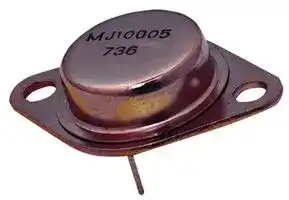
BIPOLAR TRANSISTOR, NPN, 325V, TO-3
⚠️ Reference pricing provided. In case of supply shortages, we will connect you with our trusted procurement partners to ensure your project's continuity.
- Manufacturer: NTE ELECTRONICS
- Product type: Single Bipolar Junction Transistors - BJT
- Tra; BIPOLAR TRANSISTOR, NPN, 325V, TO-3; Transistor Polarity:NPN; Collector Emitter Voltage V(br)ceo:325V; Transition Frequency ft:2.5MHz; Power Dissipation Pd:125W; DC Collector Cur
- MSL: -
- SVHC: No SVHC (17-Dec-2014)
- No. of Pins: 2Pins
- Product Range: -
- Qualification: -
- Power Dissipation: 125W
- Transistor Mounting: Through Hole
- Transistor Polarity: NPN
- Transition Frequency: 2.5MHz
- Transistor Case Style: TO-3
- DC Current Gain hFE Min: 15hFE
- Operating Temperature Max: 150°C
- Continuous Collector Current: 10A
- Collector Emitter Voltage Max: 325V
| Delivery and price | |
|---|---|
| Units per pack | 500 |
| Price | 4.05 € |
| Current stock | 10+ |
| Lead time | 30 days |
Datasheet

## **NTE162 Silicon NPN Transistor TV Vertical Deflection**

## **Description:**

The NTE162 is an NPN transistor in a TO3 type case designed for medium–to–high voltage inverters, converters, regulators, and switching circuits.

## **Features:**

High Voltage:  VCEX = 400V Gain Specified to 3.5A High Frequency Response to 2.5MHz

## **Absolute Maximum Ratings:**

|**Absolute Maximum Ratings:**||||||
|---|---|---|---|---|---|
|Collector–Emitter Voltage, VCEX|. . . . . . . . . . . . . . . . . . . . . . . . . . . . . . . . . . . . . . . . . . . . . . . . . . . . .|. . . . . . . . . . . . . . . . . . . . . . . . . . . . . . . . . . . . . . . . . . . . . . . . . . . . .|. . . . . . . . . . . . . . . . . . . . . . . . . . . . . . . . . . . . . . . . . . . . . . . . . . . . .|. . . . . . . . . . . . . . . . . . . . . . . . . . . . . . . . . . . . . . . . . . . . . . . . . . . . .|400V<br>. . . . . . . . . . . . . . . . . . . . . . . . . . . . . . . . . . . . . . . . . . . . . . . . . . . . .|
|Collector–Base Voltage, VCB<br>. . . . . . . . . . . . . . . . . . . . . . . . . . . . . . . . . . . . . . . . . . . . . . . . . . . . . . . .|. . . . . . . . . . . . . . . . . . . . . . . . . . . . . . . . . . . . . . . . . . . . . . . . . . . . . . . .|. . . . . . . . . . . . . . . . . . . . . . . . . . . . . . . . . . . . . . . . . . . . . . . . . . . . . . . .|. . . . . . . . . . . . . . . . . . . . . . . . . . . . . . . . . . . . . . . . . . . . . . . . . . . . . . . .|. . . . . . . . . . . . . . . . . . . . . . . . . . . . . . . . . . . . . . . . . . . . . . . . . . . . . . . .|400V<br>. . . . . . . . . . . . . . . . . . . . . . . . . . . . . . . . . . . . . . . . . . . . . . . . . . . . . . . .|
|Emitter–Base Voltage, VEBO<br>. . . . . . . . . . . . . . . . . . . . . . . . . . . . . . . . . . . . . . . . . . . . . . . . . . . . . . . . . .|. . . . . . . . . . . . . . . . . . . . . . . . . . . . . . . . . . . . . . . . . . . . . . . . . . . . . . . . . .|. . . . . . . . . . . . . . . . . . . . . . . . . . . . . . . . . . . . . . . . . . . . . . . . . . . . . . . . . .|. . . . . . . . . . . . . . . . . . . . . . . . . . . . . . . . . . . . . . . . . . . . . . . . . . . . . . . . . .|. . . . . . . . . . . . . . . . . . . . . . . . . . . . . . . . . . . . . . . . . . . . . . . . . . . . . . . . . .|5V<br>. . . . . . . . . . . . . . . . . . . . . . . . . . . . . . . . . . . . . . . . . . . . . . . . . . . . . . . . . .|
|Continuous Collector Current, IC||. . . . . . . . . . . . . . . . . . . . . . . . . . . . . . . . . . . . . . . . . . . . . . . . . . . . .|. . . . . . . . . . . . . . . . . . . . . . . . . . . . . . . . . . . . . . . . . . . . . . . . . . . . .|. . . . . . . . . . . . . . . . . . . . . . . . . . . . . . . . . . . . . . . . . . . . . . . . . . . . .|10A<br>. . . . . . . . . . . . . . . . . . . . . . . . . . . . . . . . . . . . . . . . . . . . . . . . . . . . .|
|Base Current, IB<br>. . . . . . . . . . . . . . . . . . . . . . . . . . . . . . . . . . . . . . . . . . . . . . . . . . . . . . . . . . . . . . . . . . . .|. . . . . . . . . . . . . . . . . . . . . . . . . . . . . . . . . . . . . . . . . . . . . . . . . . . . . . . . . . . . . . . . . . . .|. . . . . . . . . . . . . . . . . . . . . . . . . . . . . . . . . . . . . . . . . . . . . . . . . . . . . . . . . . . . . . . . . . . .|. . . . . . . . . . . . . . . . . . . . . . . . . . . . . . . . . . . . . . . . . . . . . . . . . . . . . . . . . . . . . . . . . . . .|. . . . . . . . . . . . . . . . . . . . . . . . . . . . . . . . . . . . . . . . . . . . . . . . . . . . . . . . . . . . . . . . . . . .|2A<br>. . . . . . . . . . . . . . . . . . . . . . . . . . . . . . . . . . . . . . . . . . . . . . . . . . . . . . . . . . . . . . . . . . . .|
|Total Device Dissipation (TC= +25°C), PD<br>. . . . . . . . . . . . . . . . . . . . . . . . . . . . . . . . . . . . . . . . . . .|||. . . . . . . . . . . . . . . . . . . . . . . . . . . . . . . . . . . . . . . . . . .|. . . . . . . . . . . . . . . . . . . . . . . . . . . . . . . . . . . . . . . . . . .|125W<br>. . . . . . . . . . . . . . . . . . . . . . . . . . . . . . . . . . . . . . . . . . .|
|Derate Above 25°C<br>. . . . . . . . . . . . . . . . . . . . . . . . . . . . . . . . . . . . . . . . . . . . . . . . . . . . . . . . .|. . . . . . . . . . . . . . . . . . . . . . . . . . . . . . . . . . . . . . . . . . . . . . . . . . . . . . . . .|. . . . . . . . . . . . . . . . . . . . . . . . . . . . . . . . . . . . . . . . . . . . . . . . . . . . . . . . .|. . . . . . . . . . . . . . . . . . . . . . . . . . . . . . . . . . . . . . . . . . . . . . . . . . . . . . . . .|. . . . . . . . . . . . . . . . . . . . . . . . . . . . . . . . . . . . . . . . . . . . . . . . . . . . . . . . .|1W/°C<br>. . . . . . . . . . . . . . . . . . . . . . . . . . . . . . . . . . . . . . . . . . . . . . . . . . . . . . . . .|
|Operating Junction Temperature Range, T|Operating Junction Temperature Range, TJ||. . . . . . . . . . . . . . . . . . . . . . . . . . . . . . . . . .|–65°to +150°C<br>. . . . . . . . . . . . . . . . . . . . . . . . . . . . . . . . . .||
|Storage Temperature Range, Tstg||. . . . . . . . . . . . . . . . . . . . . . . . . . . . . . . . . . . . . . . . . .|. . . . . . . . . . . . . . . . . . . . . . . . . . . . . . . . . . . . . . . . . .|–65°to +200°C<br>. . . . . . . . . . . . . . . . . . . . . . . . . . . . . . . . . . . . . . . . . .||
|Thermal Resistance, Junction–to–Case, RthJC<br>. . . . . . . . . . . . . . . . . . . . . . . . . . . . . . . . . . . . . . .||||. . . . . . . . . . . . . . . . . . . . . . . . . . . . . . . . . . . . . . .|1°C/W<br>. . . . . . . . . . . . . . . . . . . . . . . . . . . . . . . . . . . . . . .|


## **Electrical Characteristics:** (TA = +25°C unless otherwise specified)

|**Parameter**|**Symbol**|**Test Conditions**|**Min**|**Typ**|**Max**|**Unit**|
|---|---|---|---|---|---|---|
|**OFF Characteristics**|||||||
|Collector–Emitter Sustaining Voltage<br>~~ee~~|V(BR)CEO(sus)<br>~~ee~~|IC= 100mA, IB= 0, Note 1<br>~~eee~~|325|–|–|V|
|Collector Cutoff Current<br>~~ee~~|ICEX<br>~~ee~~|VCE= 400V, VEB(off)= 1.5V<br>~~eee~~|–|–|2.5||
|||VCE= 400V, VEB(off)= 1.5V,<br>TC= +125°C<br>~~eee~~|–|–|1.0|mA|
|Emitter Cutoff Current<br>~~ee~~|IEBO<br>~~ee ~~|VBE= 5V, IC= 0<br> ~~eee~~|–|–|2.0|mA|


Note 1. Pulse Test:  Pulse Width ≤ 300µs, Duty Cycle ≤ 2%.

## **Electrical Characteristics (Cont’d):** (TA = +25°C unless otherwise specified)

|**Parameter**|**Symbol**|**Test Conditions**|**Min**|**Typ**|**Max**|**Unit**|
|---|---|---|---|---|---|---|
|**ON Characteristics**(Note 1)|||||||
|DC Current Gain|hFE|IC= 2.5A, VCE= 5V|15|–|35||
|||IC= 3.5A, VCE= 5V|10|–|–||
|Collector–Emitter Saturation Voltage|VCE(sat)|IC= 2.5A, IB= 0.5A|–|–|0.7|V|
|Base–Emitter Saturation Voltage|VBE(sat)|IC= 2.5A, IB= 0.5A|–|–|1.5|V|
|**Dynamic Characteristics**|||||||
|Current Gain–Bandwidth Product|fT|IC= 200mA, VCE= 10V, f = 1MHz|2.5|–|–|MHz|


Note 1. Pulse Test:  Pulse Width ≤ 300µs, Duty Cycle ≤ 2%.

**==> picture [523 x 523] intentionally omitted <==**

**----- Start of picture text -----**<br>
.135 (3.45) Max<br>.350 (8.89) .875 (22.2)<br>Dia Max<br>Seating<br>Plane<br>.312 (7.93) Min .040 (1.02)<br>Emitter 1.187 (30.16)<br>.215 (5.45) .665<br>(16.9)<br>.156 (3.96) Dia<br>(2 Holes)<br>.430<br>(10.92)<br>.188 (4.8) R Max<br>.525 (13.35) R Max<br>Base Collector/Case<br>**----- End of picture text -----**<br>
Updated at March 10, 2026
About Novapart
Novapart is a B2B electronic component broker specialising in stock shortages and cost reduction. We source hard-to-find parts and identify compliant alternatives across a catalogue of 410,000+ components from 500+ manufacturers.
Learn more →Stock Shortage Specialist
When a component is unavailable, discontinued or has an unacceptable lead time, we tap into our network of vetted European and Asian distributors to source what you need — without compromising on quality or traceability.
Request a quote →Compliant Alternatives
We identify pin-to-pin, electrically equivalent substitutes that meet the same certifications (RoHS, AEC-Q100, REACH) as your original specification — validated against datasheets, not just part numbers. Often at a lower cost.
BOM Analysis service →