
Image not available
Illustrative purposes only

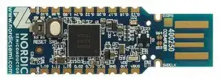
NRF52840-DONGLE
USB Dongle, Bluetooth 5.0, NRF52 Series, 2Mbps, -92dBm, 1.7 V to 5.5 V Supply
⚠️ Reference pricing provided. In case of supply shortages, we will connect you with our trusted procurement partners to ensure your project's continuity.
- Manufacturer: NORDIC SEMICONDUCTOR
- Product type: Bluetooth Modules & Adaptors
- Bluetooth Version:Bluetooth 5.0; Supply Voltage Min:1.7V; Supply Voltage Max:5.5V; Signal Range Max:-; Data Rate:2Mbps; Bluetooth Class:-; Receive Sensitivity:-92dBm; Operating T
- SVHC: No SVHC (23-Jan-2024)
- Product Range: NRF52 Series
- Bluetooth Class: -
- Bluetooth Version: Bluetooth 5.0
- Supply Voltage Range: 1.7 V to 5.5 V
| Delivery and price | |
|---|---|
| Units per pack | 250 |
| Price | 7.79 € |
| Current stock | 200+ |
| Lead time | 30 days |
Datasheet

4440_052 / 2023-05-15

## Contents

||Revision history. . . . . . . . . . . . . . . . . . . . . . . . . . . . . . . . . .|iii|
|---|---|---|
|1|Introduction. . . . . . . . . . . . . . . . . . . . . . . . . . . . . . . . . . .|4|
|2|Minimum requirements. . . . . . . . . . . . . . . . . . . . . . . . . . . .|5|
|3|Kit content. . . . . . . . . . . . . . . . . . . . . . . . . . . . . . . . . . . .|6|
||3.1 Hardware content. . . . . . . . . . . . . . . . . . . . . . . . . . . . . . . .|6|
||3.2 Downloadable content. . . . . . . . . . . . . . . . . . . . . . . . . . . . . . . 6||
||3.3 Related documentation. . . . . . . . . . . . . . . . . . . . . . . . . . . . . .|7|
|4|Getting started. . . . . . . . . . . . . . . . . . . . . . . . . . . . . . . . .|8|
|5|Programming. . . . . . . . . . . . . . . . . . . . . . . . . . . . . . . . . .|9|
|6|Hardware description. . . . . . . . . . . . . . . . . . . . . . . . . . . . .|10|
||6.1 Hardware drawings. . . . . . . . . . . . . . . . . . . . . . . . . . . . . . .|10|
||6.2 Block diagram. . . . . . . . . . . . . . . . . . . . . . . . . . . . . . . . . .|10|
||6.3 Power supply. . . . . . . . . . . . . . . . . . . . . . . . . . . . . . . . . .|11|
||6.3.1 Internal regulator. . . . . . . . . . . . . . . . . . . . . . . . . . . . . .|11|
||6.3.2 External regulated source. . . . . . . . . . . . . . . . . . . . . . . . . . .|12|
||6.4 Buttons and LEDs. . . . . . . . . . . . . . . . . . . . . . . . . . . . . . . .|12|
||6.5 32.768 kHz crystal. . . . . . . . . . . . . . . . . . . . . . . . . . . . . . . .|13|
||6.6 USB. . . . . . . . . . . . . . . . . . . . . . . . . . . . . . . . . . . . . .|13|
||6.7 SWD interface. . . . . . . . . . . . . . . . . . . . . . . . . . . . . . . . . .|14|
||6.8 External connections. . . . . . . . . . . . . . . . . . . . . . . . . . . . . . .|14|
||Legal notices. . . . . . . . . . . . . . . . . . . . . . . . . . . . . . . . . . .|15|


**==> picture [40 x 32] intentionally omitted <==**

ii

4440_052

## Revision history

|**Date**|**Description**|
|---|---|
|2023-05-15|Added safety information to:<br>•<br>Introductionon page 4<br>•<br>Internal regulatoron page 11<br>•<br>External regulated sourceon page 12|
|January 2019|UpdatedGetting startedon page 8|
|June 2018|First release|


**==> picture [40 x 32] intentionally omitted <==**

iii

4440_052

1

## Introduction

The nRF52840 Dongle (PCA10059) is the preferred hardware to be used with the nRF Connect for Desktop software package to develop and test your nRF-based wireless solutions. The hardware supports all the short range wireless standards available on the nRF52 family of devices, and the built-in USB device controller provides a high data throughput communication interface.

The nRF52840 Dongle can also be used together with the nRF5 SDK for product development based on the the nRF52840 SoC.

The nRF52840 Dongle is a low-cost, versatile USB development dongle for _Bluetooth[®]_ Low Energy, ANT[™] , 802.15.4, and user-proprietary 2.4 GHz applications using the nRF52840 SoC.

Key features:

- nRF52840 flash-based ANT/ANT+[™] , Bluetooth Low Energy SoC solution

- Button and LEDs for user interaction

- 15 GPIO available on a castellated edge

- Onboard USB bootloader with buttonless support

- USB support

**Note:** The nRF52840 Dongle must be powered by a PS1 class (IEC 62368-1) power supply with maximum power less than 15 W.

**==> picture [419 x 109] intentionally omitted <==**

**==> picture [40 x 32] intentionally omitted <==**

4

4440_052

2

## Minimum requirements

Before you start, check that you have the required hardware and software.

## **Hardware requirements**

- PC with a standard type-A USB port

## **Software requirements**

- nRF Connect for Desktop

- Operating system: macOS, Linux, or Windows 7 or later

**==> picture [40 x 32] intentionally omitted <==**

5

4440_052

Kit content 3

The nRF52840 Dongle consists of hardware (PCA10059), access to application firmware examples, documentation, hardware schematics, and layout files.

## 3.1 Hardware content

The nRF52840 Dongle hardware consists of the board (PCA10059).

_Figure 1: nRF52840 Dongle hardware (PCA10059) front_

_Figure 2: nRF52840 Dongle hardware (PCA10059) back_

The sticker on the back side of the nRF52840 Dongle contains the following information:

- Board number (PCA10059)

- Hardware revision

- Production year and week (YYYY.WK)

- MAC address/serial number

## 3.2 Downloadable content

The nRF52840 Dongle downloadable content consists of a software tool, application firmware examples, and hardware files.

6

4440_052

Kit content

## **Software**

- nRF Connect for Desktop

## **Firmware package**

In the nRF5 SDK, you can find precompiled application firmware examples.

## **Hardware files**

Schematics, layout, bill of materials, and Gerber files for nRF52840 Dongle (PCA10059) are included in a zip file:

- nRF52840 Dongle Hardware Files

## 3.3 Related documentation

In addition to the information in this document, you may need to consult other documents.

## **Nordic documentation**

- nRF52840 Product Specification

- nRF52840 Errata

- nRF52840 Compatibility Matrix

- nRF52840 Development Kit User Guide

- nRF Connect for Desktop

- nRF5 SDK v17.1.0

**==> picture [40 x 32] intentionally omitted <==**

7

4440_052

4 Getting started

Complete a few steps to set up the hardware and install the required software.

Before you start, check Minimum requirements on page 5.

Connect the Dongle to a computer and get started with nRF Connect for Desktop.

**1.** Download and install nRF Connect for Desktop.

This includes the driver for the nRF52840 USB Device Firmware Upgrade (DFU) feature. For documentation on the tool, see nRF Connect for Desktop.

**2.** Insert the nRF52840 Dongle in a USB port on your computer.

The status light (LD2) starts pulsing red, indicating that the Dongle is powered up and is in bootloader mode. After a few seconds, the computer will recognize the Dongle as a USB composite device. The driver needed for the nRF52840 USB DFU feature is also installed.

**3.** Optional: Download the nRF5 SDK.

nRF5 SDK contains application examples for the Dongle. For documentation, see nRF5 SDK v17.1.0.

**4.** Optional: Download SEGGER Embedded Studio (SES).

   - SES is needed for building application examples for the Dongle. It can be used free of charge with nRF devices.

**5.** Optional: Install nRF Util for nRF5 SDK.

nrfutil can be used for programming the Dongle from the command line.

**6.** Open an nRF Connect for Desktop app and select the serial number of the nRF52840 Dongle as the target.

Applications that support the nRF52840 Dongle will display the serial numbers of any connected Dongles in the device drop-down list.

If the app supports the Dongle but the correct firmware is missing, you will be asked to confirm that you want to have the Dongle programmed. Click **OK** .

If the Dongle contains the correct firmware, the app will start immediately.

For further information on programming the nRF52840 Dongle, see Nordic Developer Zone.

**==> picture [40 x 32] intentionally omitted <==**

8

4440_052

5

## Programming

The nRF52840 Dongle can be programmed through the built-in USB bootloader.

Before you start, check Getting started on page 8.

To program the Dongle, it must be in bootloader mode.

The Dongle can be made to enter bootloader mode in one of the two ways:

- Trigger the nRF52840 USB DFU endpoint.

The firmware to support this is embedded in all nRF Connect for Desktop apps for the nRF52840 Dongle. If you add the DFU Trigger Library (USB) to your custom device firmware, you will be able to trigger the DFU from nRF Connect for Desktop without using any buttons. For documentation, see DFU Trigger Library (USB), which is part of the nRF5 SDK v17.1.0.

- For Dongles with applications missing the USB DFU endpoint: Press the RESET button.

**==> picture [192 x 105] intentionally omitted <==**

**==> picture [53 x 59] intentionally omitted <==**

When the nRF52840 Dongle has entered the bootloader mode, **LD2** pulses red. The Dongle is now ready for programming.

All the nRF Connect for Desktop apps require specific firmware to be present on the nRF52840 Dongle to function correctly. The apps will update the firmware if needed. If you want to upload a custom firmware to the Dongle, you can do this by using the dedicated Programmer programming app, or nrfutil.

**==> picture [40 x 32] intentionally omitted <==**

9

4440_052

6

## Hardware description

The nRF52840 Dongle can be used as a development platform for the nRF52840 SoC. It features user configurable LEDs and a button as well as multiple GPIOs available along the board edges. In addition to radio communication, the nRF5240 SoC can communicate with a computer through USB.

## 6.1 Hardware drawings

The nRF52840 Dongle hardware drawings show both sides of the PCA10059 board.

**==> picture [191 x 104] intentionally omitted <==**

**==> picture [52 x 60] intentionally omitted <==**

_Figure 3: nRF52840 Dongle (PCA10059) front view_

**==> picture [209 x 105] intentionally omitted <==**

_Figure 4: nRF52840 Dongle (PCA10059) back view_

## 6.2 Block diagram

The block diagram illustrates the nRF52840 Dongle functional architecture.

**==> picture [40 x 32] intentionally omitted <==**

10

4440_052

Hardware description

**==> picture [413 x 244] intentionally omitted <==**

**----- Start of picture text -----**<br>
LEDs Button<br>GPIO Reset<br>Antenna<br>USB<br>nRF52840 Matching network<br>Debug<br>Osc Osc<br>32768 kHz 32 MHz<br>**----- End of picture text -----**<br>


_Figure 5: Block diagram_

## 6.3 Power supply

The nRF52840 Dongle can be powered from different sources.

## 6.3.1 Internal regulator

The default power supply of the nRF52840 Dongle is the USB interface. The USB interface supplies power to the on-chip high voltage regulator of the nRF52840 SoC.

**Note:** The maximum current for USB 3.0 is 0.9 A.

The output of the regulator supplies the SoC and the LEDs. The USB power connection ( **VBUS** ) is also available along the board edge. Next to **VBUS** , there is a connection point for **VDD OUT** , which is the output of the nRF52840 SoC high voltage regulator. For maximum power draw from this pad, see nRF52840 Product Specification, and take into account the power draw of the onboard nRF52840 and the LEDs.

**==> picture [192 x 104] intentionally omitted <==**

**==> picture [52 x 59] intentionally omitted <==**

_Figure 6: USB power connection (VBUS) and SoC high voltage regulator output (VDD OUT)_

**==> picture [40 x 32] intentionally omitted <==**

11

4440_052

Hardware description

By using the on-chip high voltage regulator, the VDD voltage level can be set in the REGOUT0 register in UICR. See nRF52840 Product Specification.

## 6.3.2 External regulated source

The nRF52840 Dongle can also be configured to be supplied from an external regulated 1.8–3.6 V (max 50 mA) source through the **VDD OUT** connection point. To enable this, **SB2** must be cut and **SB1** must be soldered.

**CAUTION:** Do not have both **SB1** and **SB2** connected at the same time as this will damage the nRF52840 SoC.

**==> picture [209 x 105] intentionally omitted <==**

_Figure 7: Configuring 1.8-3.6 V external source_

**Warning:** Connecting the polarity the wrong way will cause the nRF52840 Dongle to overheat.

## 6.4 Buttons and LEDs

The nRF528540 Dongle is equipped with a green LED ( **LD1** ), a multicolor RGB LED ( **LD2** ), a user configurable button ( **SW1** ), and a reset button ( **SW2** ).

The LEDs and buttons are connected to dedicated I/Os on the nRF52840 SoC.

**==> picture [191 x 105] intentionally omitted <==**

**==> picture [52 x 59] intentionally omitted <==**

_Figure 8: nRF52840 Dongle buttons and LEDs_

**==> picture [40 x 32] intentionally omitted <==**

12

4440_052

Hardware description

|**Part**|**Description**<br>**G**|**PIO**|
|---|---|---|
|SW1|Button<br>P|1.06|
|SW2|Reset<br>P|0.181|
|LD1|Green<br>P|0.06|
|LD2|Red<br>P|0.08|
|LD2|Green<br>P|1.09|
|LD2|Blue<br>P|0.12|


## _Table 1: LED connections_

The buttons are active low, which means that the input will be connected to ground when the button is activated. The **SW1** button has no external pull-up resistor, but the reset button ( **SW2** ) has a 10 k pull-up resistor. To use **SW1** , **P1.06** must be configured as an input with an internal pull-up resistor.

The LEDs are active low, which means that writing a logical zero '0' to the output pin will illuminate the LED.

## 6.5 32.768 kHz crystal

The nRF52840 Dongle is equipped with a 32.768 kHz crystal ( **X2** ) for high accuracy and low average power consumption.

**Note:** The 32.768 kHz crystal ( **X2** ) is required for correct operation when using ANT/ANT+.

## 6.6 USB

The nRF52840 Dongle features a USB-A-type connector printed on the circuit board.

Additional test points for the USB data lines are available on the bottom side of the circuit board if the nRF52840 Dongle is used as a module on a motherboard with a USB connector. To disconnect data lines from the onboard USB connector, cut solder bridges **SB3** and **SB4** .

**==> picture [191 x 104] intentionally omitted <==**

**==> picture [52 x 60] intentionally omitted <==**

_Figure 9: Disconnecting USB data lines_

- 1 **SW2** is also connected to **P0.19** , **P0.21** , **P0.23** , and **P0.25** . This is done to simplify PCB routing. These GPIOs should not be used and should be left as input with no pull or be disconnected by firmware.

**==> picture [40 x 32] intentionally omitted <==**

13

4440_052

Hardware description

## 6.7 SWD interface

On the back side of the nRF52840 Dongle, there are connection points for the SWD interface.

The dongle is equipped with a footprint for two different connectors. On footprint **P1** , a standard 2×5-pin pin header with a 1.27 mm pitch can be soldered. On footprint **J2** , it is possible to connect a TC2050 cable from Tag-Connect.

**==> picture [209 x 105] intentionally omitted <==**

_Figure 10: SWD interface connectors_

For instance, a Nordic development kit can be used as a programmer for the Dongle.

## 6.8 External connections

The nRF52840 Dongle has 15 GPIOs in addition to the ground, power, and SWD connections along the castellated edges.

The castellated edge holes have a pitch of 0.1 inches (2.54 mm) and a row spacing of 0.6 inches (15.24 mm)[2] , making it suitable for stripboard connection. Test points for additional nine GPIOs are available on the back side of the circuit board, leaving a total of 24 GPIOs accessible.

**Note:** There is no reverse voltage protection on the power connections.

> 2 The SWD connections are located 0.2 inches (5.08 mm) away from the GPIOs with a row spacing of 0.4 inches (10.16 mm)

**==> picture [40 x 32] intentionally omitted <==**

14

4440_052

## Legal notices

By using this documentation you agree to our terms and conditions of use. Nordic Semiconductor may change these terms and conditions at any time without notice.

## **Liability disclaimer**

Nordic Semiconductor ASA reserves the right to make changes without further notice to the product to improve reliability, function, or design. Nordic Semiconductor ASA does not assume any liability arising out of the application or use of any product or circuits described herein.

Nordic Semiconductor ASA does not give any representations or warranties, expressed or implied, as to the accuracy or completeness of such information and shall have no liability for the consequences of use of such information. If there are any discrepancies, ambiguities or conflicts in Nordic Semiconductor’s documentation, the Product Specification prevails.

Nordic Semiconductor ASA reserves the right to make corrections, enhancements, and other changes to this document without notice.

## **Life support applications**

Nordic Semiconductor products are not designed for use in life support appliances, devices, or systems where malfunction of these products can reasonably be expected to result in personal injury.

Nordic Semiconductor ASA customers using or selling these products for use in such applications do so at their own risk and agree to fully indemnify Nordic Semiconductor ASA for any damages resulting from such improper use or sale.

## **RoHS and REACH statement**

Complete hazardous substance reports, material composition reports and latest version of Nordic's REACH statement can be found on our website www.nordicsemi.com.

## **Trademarks**

All trademarks, service marks, trade names, product names, and logos appearing in this documentation are the property of their respective owners.

## **Copyright notice**

© 2025 Nordic Semiconductor ASA. All rights are reserved. Reproduction in whole or in part is prohibited without the prior written permission of the copyright holder.

15

4440_052
Updated at April 28, 2026
About Novapart
Novapart is a B2B electronic component broker specialising in stock shortages and cost reduction. We source hard-to-find parts and identify compliant alternatives across a catalogue of 410,000+ components from 500+ manufacturers.
Learn more →Stock Shortage Specialist
When a component is unavailable, discontinued or has an unacceptable lead time, we tap into our network of vetted European and Asian distributors to source what you need — without compromising on quality or traceability.
Request a quote →Compliant Alternatives
We identify pin-to-pin, electrically equivalent substitutes that meet the same certifications (RoHS, AEC-Q100, REACH) as your original specification — validated against datasheets, not just part numbers. Often at a lower cost.
BOM Analysis service →