
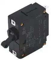


NRAS1111-1A-BA
CIRCUIT BREAKER, 1 POLE, 250VAC, 1A
- Manufacturer: IDEC
- Product type: Magnetic Hydraulic Circuit Breakers
- Trip Time: 1.3s
- No. of Poles: 1 Pole
- Product Range: NRA Series
- Current Rating: 1A
- Input Voltage VAC: 250VAC
- Dielectric Strength: 2kV
- Interrupting Capacity: 1kA
| Delivery and price | |
|---|---|
| Units per pack | 100 |
| Price | 19.94 € |
| Current stock | 10+ |
| Lead time | 30 days |
**Circuit Breakers**

**NRA Series**

## **NRA Series**

## **Features:**

- Available in 4 different styles

**==> picture [25 x 9] intentionally omitted <==**

**----- Start of picture text -----**<br>
NRAS<br>**----- End of picture text -----**<br>


**==> picture [26 x 8] intentionally omitted <==**

**----- Start of picture text -----**<br>
NRAN<br>**----- End of picture text -----**<br>


- Excellent overload and short circuit protection

- Small size and high-effi ciency

- Life expectancy of over 10,000 operations

- UL1077 recognized “Supplementary Protectors”

-

File No. E68029 License #116381

**==> picture [25 x 8] intentionally omitted <==**

**----- Start of picture text -----**<br>
NRAR<br>**----- End of picture text -----**<br>


Rocker Illuminated Rocker (with Neon lamp)

## **Specifi cations**

|**Protection Method**|Electromagnetic tripping|
|---|---|
|**Internal Circuit**|Series current trip|
|**Number of Poles**<br>**Rated Voltage**<br>**Rated Tripping Currents**<br>**Rated Interrupting Capacity**<br>**Auxiliary Contact**<br>**Alarm Contact**<br>**Reference Temperature**<br>**Operating Temperature**<br>**Insulation Resistance**<br>**Dielectric Strength**<br>**Vibration Resistance**<br>**Shock Resistance**<br>**Life Expectancy**<br>**Termination**<br>**Illumination Voltage**<br>(NRAR illuminated units)|NRAS and NRAN: 1, 2, 3<br>NRAR: 1<br>250V AC, 50/60Hz, 65V DC<br>0.3A, 0.5A, 0.75A<br>1A, 2A, 3A, 5A, 7.5A, 10A, 15A, 20A, 25A, 30A<br>250V AC, 50/60Hz, 1,000A<br>65V DC, 1,000A<br>SPDT microswitch: 250V AC, 5A (resistive load), 50V DC, 1A (resistive load)<br>SPDT microswitch: 250V AC, 5A (resistive load), 50V DC, 1A (resistive load)<br>25°C<br>–40 to +85°C (avoid freezing)<br>100MΩ (measured with 500V megger)<br>Between main circuit terminals: 2,000V AC, 1 minute<br>Between main circuit and auxiliary contact: 2,000V AC, 1 minute<br>100N (approximately 10G) (10 to 100Hz)<br>1,000N (approximately 100G)<br>Minimum 10,000 cycles (at 6 operations per minute)<br>Main terminal: Quick-connect receptacle 0.250” (accepts M3.5 screw terminal adapter)<br>Auxiliary contact, alarm contact: Quick-connect receptacle 0.080”<br>Neon: 120, 240V AC, 50/60Hz|


Not suitable for branch circuit protection.

USA: 800-262-IDEC          Canada: 888-317-IDEC

883

**Circuit Breakers**

**NRA Series**

## **Part Numbering Guide**

NRA series part numbers are composed of up to 8 part number codes. When ordering an NRA series part, select one code from each category. Example: NRAR 1 1 11 -F - 30A -AA -1

##

##

##

|NRA series part numbers are composed of up to 8 part number codes. When ordering an NRA series part, select one code from each category.<br>Example: NRAR 1 1 11 -F - 30A -AA -1|NRA series part numbers are composed of up to 8 part number codes. When ordering an NRA series part, select one code from each category.<br>Example: NRAR 1 1 11 -F - 30A -AA -1|NRA series part numbers are composed of up to 8 part number codes. When ordering an NRA series part, select one code from each category.<br>Example: NRAR 1 1 11 -F - 30A -AA -1|NRA series part numbers are composed of up to 8 part number codes. When ordering an NRA series part, select one code from each category.<br>Example: NRAR 1 1 11 -F - 30A -AA -1|NRA series part numbers are composed of up to 8 part number codes. When ordering an NRA series part, select one code from each category.<br>Example: NRAR 1 1 11 -F - 30A -AA -1|NRA series part numbers are composed of up to 8 part number codes. When ordering an NRA series part, select one code from each category.<br>Example: NRAR 1 1 11 -F - 30A -AA -1|NRA series part numbers are composed of up to 8 part number codes. When ordering an NRA series part, select one code from each category.<br>Example: NRAR 1 1 11 -F - 30A -AA -1|NRA series part numbers are composed of up to 8 part number codes. When ordering an NRA series part, select one code from each category.<br>Example: NRAR 1 1 11 -F - 30A -AA -1|NRA series part numbers are composed of up to 8 part number codes. When ordering an NRA series part, select one code from each category.<br>Example: NRAR 1 1 11 -F - 30A -AA -1|NRA series part numbers are composed of up to 8 part number codes. When ordering an NRA series part, select one code from each category.<br>Example: NRAR 1 1 11 -F - 30A -AA -1|NRA series part numbers are composed of up to 8 part number codes. When ordering an NRA series part, select one code from each category.<br>Example: NRAR 1 1 11 -F - 30A -AA -1|NRA series part numbers are composed of up to 8 part number codes. When ordering an NRA series part, select one code from each category.<br>Example: NRAR 1 1 11 -F - 30A -AA -1|||||
|---|---|---|---|---|---|---|---|---|---|---|---|---|---|---|---|
|**NRAR**<br>**1**<br>**1**<br>**11**<br>**—**<br>**F**<br>**—**<br>**30A**<br>**—**<br>**AA**<br>**—**<br>jModel<br>kPoles<br>lInternal<br>mAuxiliary and<br>nInertia Delay<br>oRated Current<br>pTime Delay Curve<br>LTJEJE<br>IE J LI Le} Le}||||||||||||**1**<br>qPilot Light*||||
|||||||Circuit|||Alarm Contacts|||||||
||**Part Number Codes: NRA Series**|||||||||||||||
|||||||**Description**|||**Part Number Code**||**Remarks**|||||
|||j**Model**<br>k**No. of Poles**<br>l**Internal Circuit**<br>m**Auxiliary and**<br>**Alarm Contacts**<br>n**Inertia Delay**<br>o**Rated Current**<br>p**Time Delay Curve**||||Lever (round cutout)<br>Lever (rectangular cutout)<br>Rocker<br>1-pole<br>2-pole<br>3-pole<br>Series current trip<br>Without<br>With auxiliary contact<br>With alarm contact<br>Without inertia delay<br>With inertia delay<br>Rated current (current trip)<br>AC curves<br>DC curves|||NRAS<br>NRAN<br>NRAR<br>1<br>2<br>3<br>1<br>00<br>11<br>21<br>Blank<br>F<br>0.3A, 0.5A, 0.75A, 1A, 2A, 3A, 5A,<br>7.5A, 10A, 15A, 20A, 25A, 30A<br>AA, BA,MA<br>AD, MD||NRAR available in 1-pole only.<br>All multi-pole circuit breakers are simultaneous<br>throw/simultaneous break.<br>All levers are mechanically interlocked.<br>Auxiliary contact switches change state with lever and/or overload condition<br>Alarm contact switches change state only with overload condition<br>All current ratings must be listed in amps (A).<br>Example conversion: 300mA = 0.30A.<br>For time delay curves, see page 888.|||||
|||q**Pilot Light***||||With neon light 120V AC (50/60Hz)<br>With neon light 240V AC (50/60Hz)|||1<br>2||*Applicable to illuminated NRAR only.|||||


1. For NRA series accessories, see page 886.

2. For NRA series time delay curves, see page 888.

3. For NRA series dimensions, see page 890.

4. Not suitable for branch circuit protection.

5. UL recognized, applicable standard: UL1077, “Supplementary Protectors.”

##

**www.idec.com**

884

**Circuit Breakers**

**NRA Series**

## **Information About Circuit Breakers**

## **Time Delay Curve Descriptions**

|**Time Delay Curve Descriptions**<br>**Time Delay Curve**<br>**NRA Application**<br>AD, AA<br>Common curves used in molded-case circuit breakers.<br>SS|
|---|
|BA<br>Response to overcurrent is quite fast. Suited for protection of semiconductor circuits with very little overload tolerance. If overcurrents are expected to<br>fl ow, fuses may be required according to the circuit characteristics.<br>MD, MA<br>Suited for motor loads that draw high inrush currents lasting a considerable length of time.<br>With Inertia Delay (F)<br>Designed not to trip on 20 times the rated current (peak value) for a duration of 8ms. Suited for transformer and lamp loads that draw steep inrush currents.|


## **Inertia Delay Description**

Circuit breakers equipped with inertia delay do not respond to high inrush currents such as those produced by transformer, lamp, or motor loads, but perform specifi ed interruption on rated overcurrents.

Specify inertia delay by inserting an “F” in the part number as shown in Part Number Guide on previous page.

**==> picture [215 x 203] intentionally omitted <==**

**----- Start of picture text -----**<br>
16,000<br>aan Fr Pulse Peak<br>14,00012,000 coer Pulse Current(duration)<br>ll Width<br>10,000<br>PNET<br>8,000<br>6,000 PINE ELEET EE<br>4,000 PLING EE<br>2,000 Pt; ALE<br>PLETEEL EE<br>1 2 3 4 5 6 7 8 9 10<br>Pulse Width (ms)<br>1. Percent of Rated Current  = Pulse Peak Current x 100%<br>Protector Rated Current<br> Percent of Rated Current<br>**----- End of picture text -----**<br>


**==> picture [164 x 8] intentionally omitted <==**

**----- Start of picture text -----**<br>
2. Based on sinusoidal or parabolic pulse profile.<br>**----- End of picture text -----**<br>


## **Notes**

## **Multi-Pole**

Multi-pole types such as 2- or 3-pole should be assembled by IDEC. **Because of their characteristics, 1-pole breakers cannot be combined to provide multi-pole units.**

## **Auxiliary and Alarm Contacts**

Multi-pole units can incorporate auxiliary and alarm contacts. **Auxiliary and alarm contacts will not work with IDEC’s DIN rail adapters.**

USA: 800-262-IDEC          Canada: 888-317-IDEC

885

**Circuit Breakers**

**NRA Series**

**Accessories**

## **Part Numbers: NRA Series Accessories**

##

##

**==> picture [541 x 199] intentionally omitted <==**

**----- Start of picture text -----**<br>
Description Appearance Part No. Remarks<br>ee ee<br>Red Ø 0.62"  NR5R  Colored<br>(15.8mm) Cap<br>Blue NR5S<br>Color Caps<br>(NRAS only) Panel<br>Yellow NR5Y<br>White NR5H  Colored caps fi t onto NRAS circuit breakers for color coding circuits<br>o e and improving the appearance of the panel. 3<br>For use on main terminals only.<br>Screw Terminal<br> NRT  Includes M3.5 clamp screw.<br>Adapter (1 pair)<br>For dimensions see page 892.<br>oS<br>Part Numbers: NRA  Mounting Accessories<br>**----- End of picture text -----**<br>


**==> picture [541 x 255] intentionally omitted <==**

**----- Start of picture text -----**<br>
For  Number Part<br>Description Appearance Remarks<br>Model of Poles Number<br>a 48.5 mm 68 mm NRANNRAR ee 1-pole  NR31 eee<br>24 mm<br>NRAN 2-pole NR32<br>| oe — =|<br>63 mm Use of a fl ush plate makes snap-in mount possible for<br>Panel Mount  NRAN, and NRAR circuit breakers (tightening screws not<br>Flush Plate necessary).<br>NRAN 3-pole NR33 Multiple units can mount in a single panel cut-out.<br>For 3-pole<br>o For 2-pole o<br>For 1-pole (Black plastic plate)<br>1-pole  NR21 1. Furnished with a hold-down spring.<br>DIN Rail  Mounting Clip NRANNRAS 2-pole NR22 2.3. Applicable only for series trip units up to 20 amps.Not applicable for NRAR lighted series.<br>Plug-in Base 3-pole NR23 4. Not for use with circuit breakers incorporating auxiliary<br>NRAR 1-pole NR211 or alarm contacts.<br>7 ==<br>1-pole  NUS1<br>NRAS<br>Surface Mount  DIN Rail For 3-pole NRAN 2-pole NUS2<br>Plug-in Base For 1-pole For 2-pole Hold-Down Spring 3-pole NUS3<br>NRAR 1-pole NUS11<br>**----- End of picture text -----**<br>


For dimensions of NRA series accessories and panel cut-out layouts, see drawings starting on page 891.

**www.idec.com**

886

**Circuit Breakers**

**NRA Series**

## **Internal Circuits and Terminal Arrangements: NRAS and NRAN Series**

**==> picture [370 x 194] intentionally omitted <==**

**----- Start of picture text -----**<br>
Series Current Trip Series Current Trip  Series Current Trip<br>with Auxiliary Contacts with Alarm Contacts<br>LINE LINE LINE<br>NC NO<br>NO NC<br>C<br>C<br>LOAD LOAD LOAD<br>LT E  ie<br>**----- End of picture text -----**<br>


**Internal Circuits and Terminal Arrangements: NRAR Series**

**==> picture [483 x 173] intentionally omitted <==**

**----- Start of picture text -----**<br>
Series Current Trip  Series Current Trip  Pilot Lights (NRAR only)<br>with Auxiliary Contacts with Alarm Contacts<br>Lead Wire<br>LOAD LOAD LOAD Pilot Light A B<br>Neon<br>White White<br>(Lead wire A) (Lead wire A) (120V AC)<br>(Lead wire B) (Lead wire B) Neon<br>(~) Black Black<br>(240V AC)<br>C C<br>Dashed lines represent NRAR<br>NO NC illuminated rocker units. Lead wires<br>(~) for neon pilot light as shown above.<br>NC NO<br>LINE LINE<br>LINE<br>**----- End of picture text -----**<br>


## **Series Current Trip**

## **Time Delay Curves (numerical equivalent)**

## **Overcurrent — Time Delay Characteristics in Seconds (at 25ºC)**

|**Curve**|**Curve**|**100%**|**125%**|**150%**|**200%**|**400%**|**600%**|**800%**|**1000%**|
|---|---|---|---|---|---|---|---|---|---|
|**AC (50/60Hz)**|**AA**|No trip<br>No trip<br>No trip|10 – 120<br>0.75 – 10<br>60 – 900|6 – 45<br>0.45 – 3.5<br>30 – 260|2.2 – 15<br>0.22 – 1.3<br>9 – 70|0.3 – 2<br>0.045 – 0.22<br>1.5 – 8|0.05 – 0.55<br>0.012 – 0.12<br>0.18 – 2.5|0.007 – 0.13<br>0.005 – 0.06<br>0.009 – 0.25|0.005 – 0.04<br>0.004 – 0.03<br>0.006 – 0.08|
||**BA**|||||||||
||**MA**|||||||||
|**DC**<br>=|**AD**<br>=|No trip<br>No trip|10 – 130<br>35 – 400|6 – 55<br>20 – 200|2.6 – 20<br>7 – 60|0.5 – 3.5<br>1.3 – 8|0.12 – 1.4<br>0.2 – 3|0.008 – 0.1<br>0.01 – 0.25|0.005 – 0.05<br>0.006 – 0.08|
||**MD**<br>=|||||||||


USA: 800-262-IDEC          Canada: 888-317-IDEC

887

**Circuit Breakers**

**NRA Series**

## **Time Delay Curves – NRA Series**

**==> picture [217 x 187] intentionally omitted <==**

**----- Start of picture text -----**<br>
1000<br>Curve AA<br>100<br>(at 25ºC)<br>fe<br>10 ro NIX TT fT<br>1 a<br>0.1 eS eS<br>———<br>0.01 |__| ff} | ff Nd<br>ee<br>L IiT; ft [ [ [ [ JT TJ<br>100 150 300 400 500 600 700 800 900 1000<br>125200<br>Current (percent load of the rated current)<br>Time in sec<br>**----- End of picture text -----**<br>


**==> picture [217 x 187] intentionally omitted <==**

**----- Start of picture text -----**<br>
1000<br>Curve BA<br>100<br>(at 25ºC)<br>pe<br>10 [itttT yy {[ T<br>1 LC NIN<br>0.1 a<br>SE<br>0.01 eee eee<br>a<br>L tity | [ J7T [ JT [ JT]<br>100 150 300 400 500 600 700 800 900 1000<br>125200<br>Current (percent load of the rated current)<br>Time in sec<br>**----- End of picture text -----**<br>


**==> picture [217 x 187] intentionally omitted <==**

**----- Start of picture text -----**<br>
1000<br>Curve MA<br>100<br>(at 25ºC)<br>10 NSN<br>1 es<br>0.1 L__[{{ | ft<br>—re<br>0.01 eS<br>SSS SSS SSS SSSSSSee<br>a<br>L iT; [ ~[ JT [~— Jf T[ JT J<br>100 150 300 400 500 600 700 800 900 1000<br>125200<br>Current (percent load of the rated current)<br>Time in sec<br>**----- End of picture text -----**<br>


## **DC Time Delay Curves**

##

**==> picture [217 x 186] intentionally omitted <==**

**----- Start of picture text -----**<br>
1000<br>Curve AD<br>100<br>(at 25ºC)<br>10 PNT No<br>1 ee<br>0.1 es<br>SS<br>0.01 ee ee eee eee<br>— ee<br>a ee ee ee ee<br>100 150 300 400 500 600 700 800 900 1000<br>125200<br>Current (percent load of the rated current)<br>Time in sec<br>**----- End of picture text -----**<br>


**==> picture [217 x 186] intentionally omitted <==**

**----- Start of picture text -----**<br>
1000<br>Curve MD<br>100<br>(at 25ºC)<br>10 LINEN<br>1 CN<br>0.1 [tft {| | {| | [~_<br>Se<br>0.01 Ltt] | | | |Ed<br>Se<br>L [ity -T [TT [ fT fT fT fT]<br>100 150 300 400 500 600 700 800 900 1000<br>125200<br>Current (percent load of the rated current)<br>Time in sec<br>**----- End of picture text -----**<br>


**www.idec.com**

888

**Circuit Breakers**

**NRA Series**

## **Resistance and Impedance Characteristics**

## **Coil Data**

|**DC Resistance**<br>PT|**AC Impedance**<br>**(50/60Hz)**<br>PT|
|---|---|
|**Curves**<br>**AD, MD**<br>PT|**Curves**<br>**AA, BA, MA**<br>PT|
|**AD, MD**<br>9.67Ω<br>3.24Ω<br>1.45Ω<br>0.90Ω<br>0.21Ω<br>0.09Ω<br>0.036Ω<br>0.017Ω<br>0.012Ω<br>0.0066Ω<br>0.0048Ω<br>0.0043Ω<br>PT|**AA, BA, MA**<br>9.82Ω<br>3.36Ω<br>1.49Ω<br>0.92Ω<br>0.21Ω<br>0.092Ω<br>0.036Ω<br>0.018Ω<br>0.012Ω<br>0.0068Ω<br>0.0048Ω<br>0.0043Ω<br>PT|


Tolerance ±25% (up to 20A), ±50% (25A and over).

## **Voltage Drop Due to Resistance or Impedance**

The internal resistance or impedance of a circuit breaker tends to be larger for a smaller rated current. Therefore, when circuit breakers with a small rated current are used, voltage drop should be taken into consideration. Internal resistance also varies with time delay curves, even at the same rated current. This should also be considered during installation.

## **Time Delay Curve and Ambient Temperature**

Since NRA series circuit breakers employ an electromagnetic tripping system, the rated current (trip current) is not affected by the ambient temperature, but the time delay varies with the oil viscosity in the tube. Lower oil viscosity at higher temperatures results in shorter delay; whereas at lower temperatures, the delay will be prolonged. The time delay curves, shown starting on page 888, are at 25°C. Time delay curves can be corrected.

**==> picture [190 x 317] intentionally omitted <==**

**----- Start of picture text -----**<br>
Impedance Correction Curve<br>100<br>LTT ETI TTT TUT TUTE TUT<br>10 LCP NET pr Curves AA, BA, and MA TT<br>CC ee<br>1 LUTE ETI TATA TTT UT<br>a<br>HRS<br>0.1 LUTE ETI ETT [ATTPT<br>a a<br>0.01<br>0.001 CERT 0.01 Cen 0.1 EE 1 FET 10 ETC 100<br>Impedance (Ω)<br>Resistance Correction Curve<br>100 DE NR<br>PIED CeCET Gam EI TOUTE UTITTOOO OO DROTITIGOOOG RATTLE THT<br>10 C CUM Curves AD and MD CC<br>a<br>Se HH<br>1 eT Te<br>POTOSI<br>0.1 Teee ee<br>CET TTTPr<br>0.01 ECO COC CEP<br>0.001 0.01 0.1 1 10 100<br>Resistance (Ω)<br>Rated Current (A)<br>Rated Current (A)<br>**----- End of picture text -----**<br>


## **Temperature Correction Curves**

**==> picture [198 x 130] intentionally omitted <==**

**----- Start of picture text -----**<br>
600 Curves AA, BA, MA,<br>500 pf ft ft ft fT tt AD, and MD<br>400 At the minimum tripping current<br>300 FEEEEEEE (125% current)<br>200<br>PRN | TE TTT Pt yy<br>100 a SC GD OG<br>80 aa RSOG<br>60 potpoof CSfy|ETfySC OO DS<br>40<br>SEE ECE eee<br>-40 -30 -20 -10 0 10 20 30 40 50 60 70 80 90<br>25<br>Ambient Temperature (ºC)<br>Change of Time Delay (%)<br>**----- End of picture text -----**<br>


USA: 800-262-IDEC          Canada: 888-317-IDEC

889

**Circuit Breakers**

**NRA Series**

## **Dimensions**

**==> picture [448 x 256] intentionally omitted <==**

**----- Start of picture text -----**<br>
NRAS<br>• [1-pole ]<br>Tab terminal #250<br>2-M3 (6.4W × 0.8t) Tab terminal #110<br>2-M3 mounting screw (2.8W × 0.5t)<br>LINE<br>OFF<br>LOAD<br>19.1 0.2 40 NRAS1111 NRAS1121<br>3.3 49.5 NRAS1111F NRAS1121F<br>17.5 53.6<br>• [2-pole ] • [3-pole ]<br>4-M3 6-M3<br>OFF OFF OFF OFF OFF<br>19.1 19.1 19.1<br>38.2 NRAS2111 NRAS2121 57.3 NRAS3111 NRAS3121<br>NRAS2111F NRAS2121F NRAS3111F NRAS3121F<br>8.2<br>NC NO<br>Switches & Pilot Lights NO NC<br>50.6 42.2 Approx. 60º 16.6 40 C C<br>30.8<br>Display Lights<br>NC NO NC NO<br>NO NC NO NC<br>C C C C<br>**----- End of picture text -----**<br>


## **NRAN**

**==> picture [469 x 386] intentionally omitted <==**

**----- Start of picture text -----**<br>
• [1-pole ]<br>Tab terminal #250<br>2-M3 (6.4W × 0.8t) Tab terminal #110<br>2-M3 mounting screw (2.8W × 0.5t)<br>LINE<br>OFF<br>LOAD<br>19.1 4.5 41<br>NRAN1111 NRAN1121<br>16.5 50.5 NRAN1111F NRAN1121F<br>54.6<br>• [2-pole ] • [3-pole ]<br>4-M3 6-M3<br>OFF OFF OFF OFF OFF<br>19.1 19.1 19.1<br>NRAS2111 NRAN2121 NRAN3111 NRAN3121<br>38.2 NRAS2111F NRAN2121F 57.3 NRAN3111F NRAN3121F<br>NRAR<br>Tab terminal #250 Indicator wire<br>(Indicator terminal)<br>LOAD LOAD<br>ON<br>OFF<br>LINE LINE<br>56 56 Tab terminal #110<br>65.5 65.5 (2.8W × 0.5t)<br>70.5 69.6<br>ia cgaa<br>8.2<br>NC NO<br>52 42.2 31.5 Approx. 60º 16.6 40 NOC NCC<br>Timers<br>NC NO NC NO<br>NO NC NO NC<br>C C C C<br>Terminal Blocks<br>52 42.2 31.5 NP 17.3 40 NP 16.6 40 NOC<br>Circuit Breakers 9.2 8.2 NC<br>**----- End of picture text -----**<br>


**www.idec.com**

890

**Circuit Breakers**

**NRA Series**

## **Panel Cut-Outs**

**==> picture [346 x 128] intentionally omitted <==**

**----- Start of picture text -----**<br>
NRAS Series NRAR, NRAN<br>ø4 Mounting hole ø4 Mounting<br>hole<br>(9.8) 19.1 19.1<br>coon :<br>—-e— _ 1-pole 19.6<br>19.1 19.1 2-pole 38.7 1-pole 19.6<br>|_| | =H | _<br>2-pole 38.7<br>3-pole 57.8<br>5.1<br>+0.3 0 ±0.25<br>ø16 42.2 55.5 42.2 32<br>26.7<br>5.1<br>**----- End of picture text -----**<br>


## **NR31, NR32, NR33 – Panel Mount Flush Plate**

**==> picture [515 x 173] intentionally omitted <==**

**----- Start of picture text -----**<br>
A Installation Angle:  Circuit breakers are designed to operate on a vertical surface. The mounting angle should not exceed a vertical plane by more than 10°.<br>Maximum Mounting Distance<br>Model A B Dimensions (mm)<br>a es ee<br>Mounting to Panel Surface Mounting to DIN Rail<br>NRAS 3.02” (77.5mm) 3.57” (91.5mm)<br>Mounting on a panel surface Mounting on a DIN rail<br>19.1 mm 20.2 mm 26 mm<br>DIN rail<br>NRAN 3.02” (77.5mm) 3.57” (91.5mm) 2-ø3.5<br>Mounting hole<br>ees NRAR 3.38” (86.7mm) 3.93” (100.7mm) TLR OLE<br>| A B<br>9mm 75 mm<br>**----- End of picture text -----**<br>


USA: 800-262-IDEC          Canada: 888-317-IDEC

891

**Circuit Breakers**

**NRA Series**

## **Accessory Dimensions**

## **NRT: Screw Terminal Adapter (for use with NRA Series)**

1. For use on main terminals only. 2. Includes M3.5 clamp screw.

## **BNDN1000 Aluminum DIN Rail**

|||||||||||||||||**Length in**|
|---|---|---|---|---|---|---|---|---|---|---|---|---|---|---|---|---|
|||||||||||||||||**Inches (mm)**|
|||||||||||||F|||A<br>B<br>C<br>D|1.4” (35mm)<br>1.14” (29mm)<br>0.78” (23mm)<br>1.2” (31mm)|
|G<br>-=--—~-~----—-4||Overall length 39.4" (1000mm)<br>H<br>!<br>-=--—~-~----—-4|||||||K<br>||||A<br>C<br>B<br>D<br>H<br>al”<br>—|—_<br>7<br>ae<br>[|e<br>|<br>y=—|--N—_1|||E<br>F<br>G<br>H<br>K|0.41” (10.5mm)<br>0.11” (3mm)<br>2” (51mm)<br>0.47” (12mm)<br>0.16” (4mm)|


**www.idec.com**

892
Updated at February 9, 2023
Founded in 1945, IDEC is a globally recognized leader in industrial automation, machine safety, and control products. Renowned for pioneering innovations in Human-Machine Interface (HMI) systems, the company is dedicated to creating a safe and efficient harmony between advanced workplace technology and human operators. At the core of IDEC’s extensive portfolio is a comprehensive selection of high-performance relays designed for demanding industrial environments. This includes a broad range of electromechanical power relays, solid-state relays, contactors, and critical safety relays, supported by a wide array of specialized relay accessories to ensure reliable and efficient switching. Beyond switching components, IDEC provides complete solutions for modern control panels and automated systems. Their robust engineering extends to advanced panel displays and instrumentation, precision light sensors, and dependable AC/DC power converters. With additional offerings in industrial switches, visual signaling units, and DIN rail terminal blocks, IDEC equips engineers with the high-quality components required to build secure, next-generation automation infrastructure.
About Novapart
Novapart is a B2B electronic component broker specialising in stock shortages and cost reduction. We source hard-to-find parts and identify compliant alternatives across a catalogue of 410,000+ components from 500+ manufacturers.
Learn more →Stock Shortage Specialist
When a component is unavailable, discontinued or has an unacceptable lead time, we tap into our network of vetted European and Asian distributors to source what you need — without compromising on quality or traceability.
Request a quote →Compliant Alternatives
We identify pin-to-pin, electrically equivalent substitutes that meet the same certifications (RoHS, AEC-Q100, REACH) as your original specification — validated against datasheets, not just part numbers. Often at a lower cost.
BOM Analysis service →