
Image not available
Illustrative purposes only

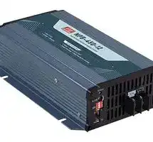
NPB-450-24NFC
Battery Charger, Universal, Lead Acid, Li-Ion, 264 V, 453.6 W, NPB-450 Series
⚠️ Reference pricing provided. In case of supply shortages, we will connect you with our trusted procurement partners to ensure your project's continuity.
- Manufacturer: MEAN WELL
- Product type:
- SVHC: No SVHC (25-Jun-2025)
- Plug Type: -
- Product Range: NPB-450 Series
- Charge Current: 13.5A
- Output Voltage: 21V to 42V
- Supply Voltage: 264VAC
- Battery Size Code: -
- Battery Charger Type: Universal
- No. of Cells Charged: -
- Battery Technologies Supported: Lead Acid, Li-Ion
| Delivery and price | |
|---|---|
| Units per pack | 10 |
| Price | 121.83 € |
| Current stock | 10+ |
| Lead time | 30 days |
Datasheet

> **450W High Reliable Ultra Wide Output Range Intelligent Battery Charger NPB-450 series**
**==> picture [102 x 5] intentionally omitted <==**
**----- Start of picture text -----**<br>
User’s Manual NFC Video<br>**----- End of picture text -----**<br>
**AC input side**
**DC output side(Non-NFC Model)**
**DC output side (NFC Model)**
**Non-NFC Mode:**
**UL62368-1 BS EN/EN62368-1 IEC62368-1 TPTC004 BS EN/EN60335-1/2-29 IEC60335-1/2-29 UL62368-1 BS EN/EN62368-1**
## **NFC Mode:**
## ■ ****
## ‧
‧
- ‧
- ‧ ‧
- ‧
- ‧
## ■ ****
## ‧
- ‧
- ‧
- ‧
- ‧
- ‧
- ‧
- ‧
- ‧
- ‧
- ‧℃℃
- ‧
## ■ ****
‧ ‧ ‧ ‧ ‧
- ‧
## ■ ****
## ■ ****
** **
{
> ~~ee~~ { | L ~~L~~
_File Name:NPB-450-SPEC 2023-09-28_
> **450W High Reliable Ultra Wide Output Range Intelligent Battery Charger NPB-450 series**
## **SPECIFICATION**
||**NPB-450-24**<br>**NPB-450-48**<br>**NPB-450-12**<br>**MODEL**<br>**FLOAT CHARGE VOLTAGE(Vfloat)(default)**<br>**RECOMMENDED BATTERY**<br>**CAPACITY (AMP HOURS)Note.5**<br>**OUTPUT**<br>**VOLTAGE RANGENote.6**<br>**FREQUENCY RANGE**<br>**POWER FACTOR (Typ.)**<br>**INPUT**<br>**ENVIRONMENT**<br>**INRUSH CURRENT (Typ.)**<br>**OVER TEMPERATURE**<br>**REVERSE POLARITY**<br>**SAFETY STANDARDS**<br>**FUNCTION**<br>**WITHSTAND VOLTAGE**<br>**ISOLATION RESISTANCE**<br>**WORKING TEMP.**<br>**CANBUS INTERFACE**<br>**TEMPERATURE COMPENSATION**<br>**WORKING HUMIDITY**<br>**STORAGE TEMP., HUMIDITY**<br>**TEMP. COEFFICIENT**<br>**VIBRATION**<br>**MTBF**<br>**DIMENSION**<br>**OTHERS**<br>**PACKING**<br>**PROTECTION**<br>14.4V<br>28.8V<br>57.6V<br>13.8V<br>27.6V<br>55.2V<br>420W<br>453.6W<br>456.96W<br>25A<br>13.5A<br>6.8A<br>90 ~ 300AH<br>45 ~ 155AH<br>24 ~ 80AH<br>90 ~ 264VAC 127 ~ 370VDC<br>47 ~ 63Hz<br>PF>0.98/115VAC, PF>0.95/230VAC at full load<br>93%<br>93%<br>92%<br>COLD START 50A at 230VAC<br>43 ~ 52V<br>82 ~ 100V<br>21.5 ~ 26V<br>Protection type : Shut down and latch off o/p voltage, re-power on to recover<br>Shut down O/P voltage, recovers automatically after temperature goes down<br>Protected internal reverse detection, No damage, re-power on to recover after fault condition is removed<br>CB IEC62368-1,<br>, Dekra BS EN/EN62368-1,<br>,UL62368-1, EAC TP TC 004approved<br>IEC60335-1/2-29<br>BS EN/EN60335-1/2-29<br>I/P-O/P:3KVAC I/P-FG:2KVAC O/P-FG:0.5KVAC<br>I/P-O/P, I/P-FG, O/P-FG:100M Ohms / 500VDC / 25℃/ 70% RH<br>-30 ~ +70℃(Refer to "Derating Curve")<br>By external NTC<br>CANBus 2.0B, Can control, Setting and monitoring(V**O**,I**O**,charging curve, internal temp. and DC output ON/OFF)<br>20 ~ 95% RH non-condensing<br>-40 ~ +85℃, 10 ~ 95% RH non-condensing<br>±0.05%/℃(0 ~ 50℃)<br>10 ~ 500Hz, 2G 10min./1cycle, 60min. each along X, Y, Z axes<br>205*135*55mm (L*W*H)<br>4.5A/115VAC 2.2A/230VAC<br>**AC CURRENT (Typ.)**<br>**CHARGE VOLTAGE RANGENote.3** 10.5 ~ 21V<br>21 ~ 42V<br>42 ~ 80V<br>**SHORT CIRCUIT Note.8**<br>**OVER VOLTAGE Note.9**<br>**EMC IMMUNITY**<br>**EMC EMISSION**<br>**Parameter**<br>**Parameter**<br>ESD<br>Radiated<br>EFT / Burst<br>Surge<br>Conducted<br>Magnetic Field<br>Voltage Dips and Interruptions<br>Conducted<br>Radiated<br>Harmonic Current<br>Voltage Flicker<br>BS EN/EN61000-6-2<br>**Standard**<br>**Standard**<br>**Test Level / Note**<br>**Test Level / Note**<br>BS EN/EN55032 (CISPR32),BS EN/EN55014-1<br>BS EN/EN55032 (CISPR32),BS EN/EN55014-1<br>BS EN/EN61000-3-2<br>BS EN/EN61000-3-3<br>BS EN/EN61000-4-2<br>BS EN/EN61000-4-3<br>BS EN/EN61000-4-4<br>BS EN/EN61000-4-5<br>BS EN/EN61000-4-6<br>BS EN/EN61000-4-8<br>BS EN/EN61000-4-11<br>Level 3, 8KV air ; Level 2, 4KV contact<br>Level 2, 3V/m<br>Level 2, 1KV<br>Level 2, 1KV/Line-Line,Level 3, 2KV/Line-Earth<br>Level 2, 3Vrms<br>Level 1, 1A/m<br>>95% dip 0.5 periods, 30% dip 25 periods,<br>>95% interruptions 250 periods<br>Class B<br>Class B<br>Class A<br>-----<br>1. Modification for charger specification may be required for different battery specification. Please contact battery vendor and MEAN WELL for details.<br>2. All parameters NOT specially mentioned are measured at 230VAC input, rated load and 25℃of ambient temperature.<br>3. This is the range when programming Vboost or Vfloat by using SBP-001, the smart battery charging programmer.<br><br>5. This is MEAN WELL's suggested range. Please consult your battery manufacturer for their suggestions about maximum charging current limitation.<br>6. Derating may be needed under low input voltages. Please check the derating curve for more details.<br><br><br>8. This protection mechanism is specified for the case the short circuit occurs after the charger is turned on.<br><br><br><br><br><br><br><br>(as available on http://www.meanwell.com)<br>℃℃<br>※<br>https://www.meanwell.com/serviceDisclaimer.aspx<br>:<br>**NOTE**<br>**SAFETY &**<br>**MAX. POWER Note.4**<br>**MAX. OUTPUT CURRENT(CC) Note.4**<br>**EFFICIENCY (Typ.) Note.7**<br>**EMC**<br>**(Note 10)**<br>Protection type : Constant current limiting, charger will shutdown after 5 sec, re-power on to recover<br>**LEAKAGE** **CURRENT**<br><0.75mA/240VAC<br>**LEAKAGE CURRENT**<br>**FROM BATTERY (Typ.)**<br><1mA<br>**BOOST CHARGE VOLTAGE(Vboost)(default)**<br>Depends on internal temperature<br>Please refer to functin manual for more detail (page 10)<br>Programmable: Constant current(CC),Tapper current(TC), Constant voltage(CV) and Float voltage(FV)<br>can be set through SBP-001 with computer<br>Charging current<br>by via potentiometer on panel (Only for auto ranging mode)<br>adjustable 50~100%<br>Manual setting: 4 built-in charging curves adjustable via DIP S.W on panel, Please refer to function manual for more detail<br>**FAN SPEED CONTROL**<br>**AUTO RANGING FOR**<br>**CHARGING (Typ.)**<br>**CHARGING PARAMETERS**<br>**ADJUSTABLE**<br>**CHARGING STAGE**<br>2 or 3 stage selectable through DIP S.W on panel<br>**BATTERY FULL SIGNAL**<br>**CHARGER OK**<br>The TTL signal out, Charger OK = H(4.5 ~ 5.5V) ; Charger failure or protection status =L( -0.5 ~ +0.5V)<br>The TTL signal out, Battery full = H(4.5 ~ 5.5V ); Charging = L(-0.5 ~ +0.5V)<br>**REMOTE CONTROL**<br>Short : Charger normal work Open : Charger stop charging<br>**NPB-450-72**<br>72V<br>69V<br>462W<br>5.5A<br>19 ~ 64AH<br>93%<br>102 ~ 120V<br>54 ~ 100V<br>1.02Kg; 8pcs/ 10Kg / 1.71CUFT<br>821.0K hrs min. Telcordia SR-332 (Bellcore) ; 83.4K hrs min. MIL-HDBK-217F (25℃)|**NPB-450-24**<br>**NPB-450-48**<br>**NPB-450-12**<br>**MODEL**<br>**FLOAT CHARGE VOLTAGE(Vfloat)(default)**<br>**RECOMMENDED BATTERY**<br>**CAPACITY (AMP HOURS)Note.5**<br>**OUTPUT**<br>**VOLTAGE RANGENote.6**<br>**FREQUENCY RANGE**<br>**POWER FACTOR (Typ.)**<br>**INPUT**<br>**ENVIRONMENT**<br>**INRUSH CURRENT (Typ.)**<br>**OVER TEMPERATURE**<br>**REVERSE POLARITY**<br>**SAFETY STANDARDS**<br>**FUNCTION**<br>**WITHSTAND VOLTAGE**<br>**ISOLATION RESISTANCE**<br>**WORKING TEMP.**<br>**CANBUS INTERFACE**<br>**TEMPERATURE COMPENSATION**<br>**WORKING HUMIDITY**<br>**STORAGE TEMP., HUMIDITY**<br>**TEMP. COEFFICIENT**<br>**VIBRATION**<br>**MTBF**<br>**DIMENSION**<br>**OTHERS**<br>**PACKING**<br>**PROTECTION**<br>14.4V<br>28.8V<br>57.6V<br>13.8V<br>27.6V<br>55.2V<br>420W<br>453.6W<br>456.96W<br>25A<br>13.5A<br>6.8A<br>90 ~ 300AH<br>45 ~ 155AH<br>24 ~ 80AH<br>90 ~ 264VAC 127 ~ 370VDC<br>47 ~ 63Hz<br>PF>0.98/115VAC, PF>0.95/230VAC at full load<br>93%<br>93%<br>92%<br>COLD START 50A at 230VAC<br>43 ~ 52V<br>82 ~ 100V<br>21.5 ~ 26V<br>Protection type : Shut down and latch off o/p voltage, re-power on to recover<br>Shut down O/P voltage, recovers automatically after temperature goes down<br>Protected internal reverse detection, No damage, re-power on to recover after fault condition is removed<br>CB IEC62368-1,<br>, Dekra BS EN/EN62368-1,<br>,UL62368-1, EAC TP TC 004approved<br>IEC60335-1/2-29<br>BS EN/EN60335-1/2-29<br>I/P-O/P:3KVAC I/P-FG:2KVAC O/P-FG:0.5KVAC<br>I/P-O/P, I/P-FG, O/P-FG:100M Ohms / 500VDC / 25℃/ 70% RH<br>-30 ~ +70℃(Refer to "Derating Curve")<br>By external NTC<br>CANBus 2.0B, Can control, Setting and monitoring(V**O**,I**O**,charging curve, internal temp. and DC output ON/OFF)<br>20 ~ 95% RH non-condensing<br>-40 ~ +85℃, 10 ~ 95% RH non-condensing<br>±0.05%/℃(0 ~ 50℃)<br>10 ~ 500Hz, 2G 10min./1cycle, 60min. each along X, Y, Z axes<br>205*135*55mm (L*W*H)<br>4.5A/115VAC 2.2A/230VAC<br>**AC CURRENT (Typ.)**<br>**CHARGE VOLTAGE RANGENote.3** 10.5 ~ 21V<br>21 ~ 42V<br>42 ~ 80V<br>**SHORT CIRCUIT Note.8**<br>**OVER VOLTAGE Note.9**<br>**EMC IMMUNITY**<br>**EMC EMISSION**<br>**Parameter**<br>**Parameter**<br>ESD<br>Radiated<br>EFT / Burst<br>Surge<br>Conducted<br>Magnetic Field<br>Voltage Dips and Interruptions<br>Conducted<br>Radiated<br>Harmonic Current<br>Voltage Flicker<br>BS EN/EN61000-6-2<br>**Standard**<br>**Standard**<br>**Test Level / Note**<br>**Test Level / Note**<br>BS EN/EN55032 (CISPR32),BS EN/EN55014-1<br>BS EN/EN55032 (CISPR32),BS EN/EN55014-1<br>BS EN/EN61000-3-2<br>BS EN/EN61000-3-3<br>BS EN/EN61000-4-2<br>BS EN/EN61000-4-3<br>BS EN/EN61000-4-4<br>BS EN/EN61000-4-5<br>BS EN/EN61000-4-6<br>BS EN/EN61000-4-8<br>BS EN/EN61000-4-11<br>Level 3, 8KV air ; Level 2, 4KV contact<br>Level 2, 3V/m<br>Level 2, 1KV<br>Level 2, 1KV/Line-Line,Level 3, 2KV/Line-Earth<br>Level 2, 3Vrms<br>Level 1, 1A/m<br>>95% dip 0.5 periods, 30% dip 25 periods,<br>>95% interruptions 250 periods<br>Class B<br>Class B<br>Class A<br>-----<br>1. Modification for charger specification may be required for different battery specification. Please contact battery vendor and MEAN WELL for details.<br>2. All parameters NOT specially mentioned are measured at 230VAC input, rated load and 25℃of ambient temperature.<br>3. This is the range when programming Vboost or Vfloat by using SBP-001, the smart battery charging programmer.<br><br>5. This is MEAN WELL's suggested range. Please consult your battery manufacturer for their suggestions about maximum charging current limitation.<br>6. Derating may be needed under low input voltages. Please check the derating curve for more details.<br><br><br>8. This protection mechanism is specified for the case the short circuit occurs after the charger is turned on.<br><br><br><br><br><br><br><br>(as available on http://www.meanwell.com)<br>℃℃<br>※<br>https://www.meanwell.com/serviceDisclaimer.aspx<br>:<br>**NOTE**<br>**SAFETY &**<br>**MAX. POWER Note.4**<br>**MAX. OUTPUT CURRENT(CC) Note.4**<br>**EFFICIENCY (Typ.) Note.7**<br>**EMC**<br>**(Note 10)**<br>Protection type : Constant current limiting, charger will shutdown after 5 sec, re-power on to recover<br>**LEAKAGE** **CURRENT**<br><0.75mA/240VAC<br>**LEAKAGE CURRENT**<br>**FROM BATTERY (Typ.)**<br><1mA<br>**BOOST CHARGE VOLTAGE(Vboost)(default)**<br>Depends on internal temperature<br>Please refer to functin manual for more detail (page 10)<br>Programmable: Constant current(CC),Tapper current(TC), Constant voltage(CV) and Float voltage(FV)<br>can be set through SBP-001 with computer<br>Charging current<br>by via potentiometer on panel (Only for auto ranging mode)<br>adjustable 50~100%<br>Manual setting: 4 built-in charging curves adjustable via DIP S.W on panel, Please refer to function manual for more detail<br>**FAN SPEED CONTROL**<br>**AUTO RANGING FOR**<br>**CHARGING (Typ.)**<br>**CHARGING PARAMETERS**<br>**ADJUSTABLE**<br>**CHARGING STAGE**<br>2 or 3 stage selectable through DIP S.W on panel<br>**BATTERY FULL SIGNAL**<br>**CHARGER OK**<br>The TTL signal out, Charger OK = H(4.5 ~ 5.5V) ; Charger failure or protection status =L( -0.5 ~ +0.5V)<br>The TTL signal out, Battery full = H(4.5 ~ 5.5V ); Charging = L(-0.5 ~ +0.5V)<br>**REMOTE CONTROL**<br>Short : Charger normal work Open : Charger stop charging<br>**NPB-450-72**<br>72V<br>69V<br>462W<br>5.5A<br>19 ~ 64AH<br>93%<br>102 ~ 120V<br>54 ~ 100V<br>1.02Kg; 8pcs/ 10Kg / 1.71CUFT<br>821.0K hrs min. Telcordia SR-332 (Bellcore) ; 83.4K hrs min. MIL-HDBK-217F (25℃)|**NPB-450-12**|**NPB-450-24**|**NPB-450-24**|**NPB-450-48**|**NPB-450-48**|**NPB-450-72**|
|---|---|---|---|---|---|---|---|---|
|||**BOOST CHARGE VOLTAGE(Vboost)(default)**|14.4V|28.8V||57.6V||72V|
|||**FLOAT CHARGE VOLTAGE(Vfloat)(default)**|13.8V|27.6V||55.2V||69V|
|||**CHARGE VOLTAGE RANGENote.3**|10.5 ~ 21V|21 ~ 42V||42 ~ 80V||54 ~ 100V|
|||**MAX. OUTPUT CURRENT(CC) Note.4**|25A|13.5A||6.8A||5.5A|
|||**MAX. POWER Note.4**|420W|453.6W||456.96W||462W|
|||**RECOMMENDED BATTERY**<br>**CAPACITY (AMP HOURS)Note.5**|90 ~ 300AH|45 ~ 155AH||24 ~ 80AH||19 ~ 64AH|
|||**LEAKAGE CURRENT**<br>**FROM BATTERY (Typ.)**|<1mA||||||
|||**VOLTAGE RANGENote.6**|90 ~ 264VAC 127 ~ 370VDC||||||
|||**FREQUENCY RANGE**|47 ~ 63Hz||||||
|||**POWER FACTOR (Typ.)**|PF>0.98/115VAC, PF>0.95/230VAC at full load||||||
|||**EFFICIENCY (Typ.) Note.7**|92%|93%||93%||93%|
|||**AC CURRENT (Typ.)**|4.5A/115VAC 2.2A/230VAC||||||
|||**INRUSH CURRENT (Typ.)**|COLD START 50A at 230VAC||||||
|||**LEAKAGE** **CURRENT**|<0.75mA/240VAC||||||
|||**SHORT CIRCUIT Note.8**|Protection type : Constant current limiting, charger will shutdown after 5 sec, re-power on to recover||||||
|||**OVER VOLTAGE Note.9**|43 ~ 52V<br>82 ~ 100V<br>21.5 ~ 26V<br>Protection type : Shut down and latch off o/p voltage, re-power on to recover<br>102 ~ 120V||||||
|||**REVERSE POLARITY**|Protected internal reverse detection, No damage, re-power on to recover after fault condition is removed||||||
|||**OVER TEMPERATURE**|Shut down O/P voltage, recovers automatically after temperature goes down||||||
|||**CHARGING STAGE**|2 or 3 stage selectable through DIP S.W on panel||||||
|||**CHARGING PARAMETERS**<br>**ADJUSTABLE**|Programmable: Constant current(CC),Tapper current(TC), Constant voltage(CV) and Float voltage(FV)<br>can be set through SBP-001 with computer<br>Manual setting: 4 built-in charging curves adjustable via DIP S.W on panel, Please refer to function manual for more detail||||||
|||**AUTO RANGING FOR**<br>**CHARGING (Typ.)**|Please refer to functin manual for more detail (page 10)<br>Charging current<br>by via potentiometer on panel (Only for auto ranging mode)<br>adjustable 50~100%||||||
|||**CANBUS INTERFACE**|CANBus 2.0B, Can control, Setting and monitoring(V**O**,I**O**,charging curve, internal temp. and DC output ON/OFF)||||||
|||**CHARGER OK**|The TTL signal out, Charger OK = H(4.5 ~ 5.5V) ; Charger failure or protection status =L( -0.5 ~ +0.5V)||||||
|||**BATTERY FULL SIGNAL**|The TTL signal out, Battery full = H(4.5 ~ 5.5V ); Charging = L(-0.5 ~ +0.5V)||||||
|||**REMOTE CONTROL**|Short : Charger normal work Open : Charger stop charging||||||
|||**TEMPERATURE COMPENSATION**|By external NTC||||||
|||**FAN SPEED CONTROL**|Depends on internal temperature||||||
|||**WORKING TEMP.**|-30 ~ +70℃(Refer to "Derating Curve")||||||
|||**WORKING HUMIDITY**|20 ~ 95% RH non-condensing||||||
|||**STORAGE TEMP., HUMIDITY**|-40 ~ +85℃, 10 ~ 95% RH non-condensing||||||
|||**TEMP. COEFFICIENT**|±0.05%/℃(0 ~ 50℃)||||||
|||**VIBRATION**|10 ~ 500Hz, 2G 10min./1cycle, 60min. each along X, Y, Z axes||||||
|||**SAFETY STANDARDS**|CB IEC62368-1,<br>, Dekra BS EN/EN62368-1,<br>,UL62368-1, EAC TP TC 004approved<br>IEC60335-1/2-29<br>BS EN/EN60335-1/2-29||||||
|||**WITHSTAND VOLTAGE**|I/P-O/P:3KVAC I/P-FG:2KVAC O/P-FG:0.5KVAC||||||
|||**ISOLATION RESISTANCE**|I/P-O/P, I/P-FG, O/P-FG:100M Ohms / 500VDC / 25℃/ 70% RH||||||
|||**MTBF**<br>**EMC IMMUNITY**<br>**EMC EMISSION**|**Parameter**||**Standard**||**Test Level / Note**||
||||Conducted||BS EN/EN55032 (CISPR32),BS EN/EN55014-1||<br>Class B||
||||Radiated||BS EN/EN55032 (CISPR32),BS EN/EN55014-1||<br>Class B||
||||Harmonic Current||BS EN/EN61000-3-2||Class A||
||||Voltage Flicker||BS EN/EN61000-3-3||-----||
||||BS EN/EN61000-6-2||||||
||||**Parameter**||**Standard**||**Test Level / Note**||
||||ESD||BS EN/EN61000-4-2||Level 3, 8KV air ; Level 2, 4KV contact||
||||Radiated||BS EN/EN61000-4-3||Level 2, 3V/m||
||||EFT / Burst||BS EN/EN61000-4-4||Level 2, 1KV||
||||Surge||BS EN/EN61000-4-5||Level 2, 1KV/Line-Line,Level 3, 2KV/Line-Earth||
||||Conducted||BS EN/EN61000-4-6||Level 2, 3Vrms||
||||Magnetic Field||BS EN/EN61000-4-8||Level 1, 1A/m||
||||Voltage Dips and Interruptions||BS EN/EN61000-4-11||>95% dip 0.5 periods, 30% dip 25 periods,<br>>95% interruptions 250 periods||
||||821.0K hrs min. Telcordia SR-332 (Bellcore) ; 83.4K hrs min. MIL-HDBK-217F (25℃)||||||
|||**DIMENSION**|205*135*55mm (L*W*H)||||||
|||**PACKING**<br>1. Modification for charger specification may be required for different battery specification. Please contact battery vendor and MEAN WELL for details.<br>2. All parameters NOT specially mentioned are measured at 230VAC input, rated load and 25℃of ambient temperature.<br>3. This is the range when programming Vboost or Vfloat by using SBP-001, the smart battery charging programmer.<br><br>5. This is MEAN WELL's suggested range. Please consult your battery manufacturer for their suggestions about maximum charging current limitation.<br>6. Derating may be needed under low input voltages. Please check the derating curve for more details.<br><br><br>8. This protection mechanism is specified for the case the short circuit occurs after the charger is turned on.<br><br><br><br><br><br><br><br>(as available on http://www.meanwell.com)<br>℃℃<br>※<br>https://www.meanwell.com/serviceDisclaimer.aspx<br>:<br>1.02Kg; 8pcs/ 10Kg / 1.71CUFT|||||||
_File Name:NPB-450-SPEC 2023-09-28_
> **450W High Reliable Ultra Wide Output Range Intelligent Battery Charger NPB-450 series**
## **SPECIFICATION**
|**NPB-450-24NFC**<br>**NPB-450-48NFC**<br>**NPB-450-12NFC**<br>**MODEL**<br>**FLOAT CHARGE VOLTAGE(Vfloat)(default)**<br>**RECOMMENDED BATTERY**<br>**CAPACITY (AMP HOURS)Note.5**<br>**OUTPUT**<br>**VOLTAGE RANGENote.6**<br>**FREQUENCY RANGE**<br>**POWER FACTOR (Typ.)**<br>**INPUT**<br>**ENVIRONMENT**<br>**INRUSH CURRENT (Typ.)**<br>**OVER TEMPERATURE**<br>**REVERSE POLARITY**<br>**SAFETY STANDARDS**<br>**FUNCTION**<br>**WITHSTAND VOLTAGE**<br>**ISOLATION RESISTANCE**<br>**WORKING TEMP.**<br>**CANBu**s**INTERFACE**<br>**TEMPERATURE COMPENSATION**<br>**WORKING HUMIDITY**<br>**STORAGE TEMP., HUMIDITY**<br>**TEMP. COEFFICIENT**<br>**VIBRATION**<br>**MTBF**<br>**DIMENSION**<br>**OTHERS**<br>**PACKING**<br>**PROTECTION**<br>14.4V<br>28.8V<br>57.6V<br>13.8V<br>27.6V<br>55.2V<br>420W<br>453.6W<br>456.96W<br>25A<br>13.5A<br>6.8A<br>90 ~ 300AH<br>45 ~ 155AH<br>24 ~ 80AH<br>90 ~ 264VAC 127 ~ 370VDC<br>47 ~ 63Hz<br>PF>0.98/115VAC, PF>0.95/230VAC at full load<br>93%<br>93%<br>92%<br>COLD START 50A at 230VAC<br>43 ~ 52V<br>82 ~ 100V<br>21.5 ~ 26V<br>Protection type : Shut down and latch off o/p voltage, re-power on to recover<br>Shut down O/P voltage, recovers automatically after temperature goes down<br>Protected internal reverse detection, No damage, re-power on to recover after fault condition is removed<br>Dekra BS EN/EN62368-1,UL62368-1approved<br>I/P-O/P:3KVAC I/P-FG:2KVAC O/P-FG:0.5KVAC<br>I/P-O/P, I/P-FG, O/P-FG:100M Ohms / 500VDC / 25℃/ 70% RH<br>-30 ~ +70℃(Refer to "Derating Curve")<br>By external NTC<br>CANBus 2.0B, Can control, Setting and monitoring(V**O**,I**O**,charging curve, internal temp. and DC output ON/OFF)<br>20 ~ 95% RH non-condensing<br>-40 ~ +85℃, 10 ~ 95% RH non-condensing<br>±0.05%/℃(0 ~ 50℃)<br>10 ~ 500Hz, 2G 10min./1cycle, 60min. each along X, Y, Z axes<br>205*135*55mm (L*W*H)<br>4.5A/115VAC 2.2A/230VAC<br>**AC CURRENT (Typ.)**<br>**CHARGE VOLTAGE RANGENote.3** 10.5 ~ 21V<br>21 ~ 42V<br>42 ~ 80V<br>**SHORT CIRCUIT Note.8**<br>**OVER VOLTAGE Note.9**<br>**EMC IMMUNITY**<br>**EMC EMISSION**<br>**Parameter**<br>**Parameter**<br>ESD<br>Radiated<br>EFT / Burst<br>Surge<br>Conducted<br>Magnetic Field<br>Voltage Dips and Interruptions<br>Conducted<br>Radiated<br>Harmonic Current<br>Voltage Flicker<br>BS EN/EN61000-6-2<br>**Standard**<br>**Standard**<br>**Test Level / Note**<br>**Test Level / Note**<br>BS EN/EN55032 (CISPR32),BS EN/EN55014-1<br>BS EN/EN55032 (CISPR32),BS EN/EN55014-1<br>BS EN/EN61000-3-2<br>BS EN/EN61000-3-3<br>BS EN/EN61000-4-2<br>BS EN/EN61000-4-3<br>BS EN/EN61000-4-4<br>BS EN/EN61000-4-5<br>BS EN/EN61000-4-6<br>BS EN/EN61000-4-8<br>BS EN/EN61000-4-11<br>Level 3, 8KV air ; Level 2, 4KV contact<br>Level 2, 3V/m<br>Level 2, 1KV<br>Level 2, 1KV/Line-Line,Level 3, 2KV/Line-Earth<br>Level 2, 3Vrms<br>Level 1, 1A/m<br>>95% dip 0.5 periods, 30% dip 25 periods,<br>>95% interruptions 250 periods<br>Class B<br>Class B<br>Class A<br>-----<br>1. Modification for charger specification may be required for different battery specification. Please contact battery vendor and MEAN WELL for details.<br>2. All parameters NOT specially mentioned are measured at 230VAC input, rated load and 25℃of ambient temperature.<br>3. This is the range when programming Vboost or Vfloat by using SBP-001 or NFC settings through MEAN WELL APP, the smart battery charging programmer.<br><br>5. This is MEAN WELL's suggested range. Please consult your battery manufacturer for their suggestions about maximum charging current limitation.<br>6. Derating may be needed under low input voltages. Please check the derating curve for more details.<br><br><br>8. This protection mechanism is specified for the case the short circuit occurs after the charger is turned on.<br><br><br><br><br><br><br><br>(as available on http://www.meanwell.com)<br>℃℃<br>※<br>https://www.meanwell.com/serviceDisclaimer.aspx<br>:<br>**NOTE**<br>**SAFETY &**<br>**MAX. POWER Note.4**<br>**MAX. OUTPUT CURRENT(CC) Note.4**<br>**EFFICIENCY (Typ.) Note.7**<br>**EMC**<br>**(Note 10)**<br>Protection type : Constant current limiting, charger will shutdown after 5 sec, re-power on to recover<br>**LEAKAGE** **CURRENT**<br><0.75mA/240VAC<br>**LEAKAGE CURRENT**<br>**FROM BATTERY (Typ.)**<br><1mA<br>**BOOST CHARGE VOLTAGE(Vboost)(default)**<br>Depends on internal temperature<br>Please refer to functin manual for more detail (page 10)<br>Programmable: Constant current(CC),Tapper current(TC), Constant voltage(CV) and Float voltage(FV)<br>can be set through SBP-001with computer or using NFC through APP<br>Charging current<br>by via potentiometer on panel (Only for auto ranging mode)<br>adjustable 50~100%<br>Manual setting: 4 built-in charging curves adjustable via DIP S.W on panel, Please refer to function manual for more detail<br>**FAN SPEED CONTROL**<br>**AUTO RANGING FOR**<br>**CHARGING (Typ.)**<br>**CHARGING PARAMETERS**<br>**ADJUSTABLE**<br>**CHARGING STAGE**<br>2/3 stage charging can be selected through NFC<br>**BATTERY FULL SIGNAL**<br>**CHARGER OK**<br>The TTL signal out, Charger OK = H(4.5 ~ 5.5V) ; Charger failure or protection status =L( -0.5 ~ +0.5V)<br>The TTL signal out, Battery full = H(4.5 ~ 5.5V ); Charging = L(-0.5 ~ +0.5V)<br>**REMOTE CONTROL**<br>Short : Charger normal work Open : Charger stop charging<br>**NPB-450-72NFC**<br>72V<br>69V<br>462W<br>5.5A<br>19 ~ 64AH<br>93%<br>102 ~ 120V<br>54 ~ 100V<br>1.02Kg; 8pcs/ 10Kg / 1.71CUFT<br>821.0K hrs min. Telcordia SR-332 (Bellcore) ; 83.4K hrs min. MIL-HDBK-217F (25℃)<br>**NFC INTERFACE**<br>Set up charging parameters easily via<br>interface<br>NFC|**MODEL**<br>**FLOAT CHARGE VOLTAGE(Vfloat)(default)**<br>**RECOMMENDED BATTERY**<br>**CAPACITY (AMP HOURS)Note.5**<br>**OUTPUT**<br>**VOLTAGE RANGENote.6**<br>**FREQUENCY RANGE**<br>**POWER FACTOR (Typ.)**<br>**INPUT**<br>**ENVIRONMENT**<br>**INRUSH CURRENT (Typ.)**<br>**OVER TEMPERATURE**<br>**REVERSE POLARITY**<br>**SAFETY STANDARDS**<br>**FUNCTION**<br>**WITHSTAND VOLTAGE**<br>**ISOLATION RESISTANCE**<br>**WORKING TEMP.**<br>**CANBu**s**INTERFACE**<br>**TEMPERATURE COMPENSATION**<br>**WORKING HUMIDITY**<br>**STORAGE TEMP., HUMIDITY**<br>**TEMP. COEFFICIENT**<br>**VIBRATION**<br>**MTBF**<br>**DIMENSION**<br>**OTHERS**<br>**PACKING**<br>**PROTECTION**<br>**AC CURRENT (Typ.)**<br>**CHARGE VOLTAGE RANGENote.3** <br>**SHORT CIRCUIT Note.8**<br>**OVER VOLTAGE Note.9**<br>**EMC IMMUNITY**<br>**EMC EMISSION**<br>**SAFETY &**<br>**MAX. POWER Note.4**<br>**MAX. OUTPUT CURRENT(CC) Note.4**<br>**EFFICIENCY (Typ.) Note.7**<br>**EMC**<br>**(Note 10)**<br>**LEAKAGE** **CURRENT**<br>**LEAKAGE CURRENT**<br>**FROM BATTERY (Typ.)**<br>**BOOST CHARGE VOLTAGE(Vboost)(default)**<br>**FAN SPEED CONTROL**<br>**AUTO RANGING FOR**<br>**CHARGING (Typ.)**<br>**CHARGING PARAMETERS**<br>**ADJUSTABLE**<br>**CHARGING STAGE**<br>**BATTERY FULL SIGNAL**<br>**CHARGER OK**<br>**REMOTE CONTROL**<br>**NFC INTERFACE**|**MODEL**<br>**FLOAT CHARGE VOLTAGE(Vfloat)(default)**<br>**RECOMMENDED BATTERY**<br>**CAPACITY (AMP HOURS)Note.5**<br>**OUTPUT**<br>**VOLTAGE RANGENote.6**<br>**FREQUENCY RANGE**<br>**POWER FACTOR (Typ.)**<br>**INPUT**<br>**ENVIRONMENT**<br>**INRUSH CURRENT (Typ.)**<br>**OVER TEMPERATURE**<br>**REVERSE POLARITY**<br>**SAFETY STANDARDS**<br>**FUNCTION**<br>**WITHSTAND VOLTAGE**<br>**ISOLATION RESISTANCE**<br>**WORKING TEMP.**<br>**CANBu**s**INTERFACE**<br>**TEMPERATURE COMPENSATION**<br>**WORKING HUMIDITY**<br>**STORAGE TEMP., HUMIDITY**<br>**TEMP. COEFFICIENT**<br>**VIBRATION**<br>**MTBF**<br>**DIMENSION**<br>**OTHERS**<br>**PACKING**<br>**PROTECTION**<br>**AC CURRENT (Typ.)**<br>**CHARGE VOLTAGE RANGENote.3** <br>**SHORT CIRCUIT Note.8**<br>**OVER VOLTAGE Note.9**<br>**EMC IMMUNITY**<br>**EMC EMISSION**<br>**SAFETY &**<br>**MAX. POWER Note.4**<br>**MAX. OUTPUT CURRENT(CC) Note.4**<br>**EFFICIENCY (Typ.) Note.7**<br>**EMC**<br>**(Note 10)**<br>**LEAKAGE** **CURRENT**<br>**LEAKAGE CURRENT**<br>**FROM BATTERY (Typ.)**<br>**BOOST CHARGE VOLTAGE(Vboost)(default)**<br>**FAN SPEED CONTROL**<br>**AUTO RANGING FOR**<br>**CHARGING (Typ.)**<br>**CHARGING PARAMETERS**<br>**ADJUSTABLE**<br>**CHARGING STAGE**<br>**BATTERY FULL SIGNAL**<br>**CHARGER OK**<br>**REMOTE CONTROL**<br>**NFC INTERFACE**|**NPB-450-12NFC**|**NPB-450-24NFC**|**NPB-450-24NFC**|**NPB-450-48NFC**|**NPB-450-48NFC**|**NPB-450-72NFC**|
|---|---|---|---|---|---|---|---|---|
|||**BOOST CHARGE VOLTAGE(Vboost)(default)**|14.4V|28.8V||57.6V||72V|
|||**FLOAT CHARGE VOLTAGE(Vfloat)(default)**|13.8V|27.6V||55.2V||69V|
|||**CHARGE VOLTAGE RANGENote.3**|10.5 ~ 21V|21 ~ 42V||42 ~ 80V||54 ~ 100V|
|||**MAX. OUTPUT CURRENT(CC) Note.4**|25A|13.5A||6.8A||5.5A|
|||**MAX. POWER Note.4**|420W|453.6W||456.96W||462W|
|||**RECOMMENDED BATTERY**<br>**CAPACITY (AMP HOURS)Note.5**|90 ~ 300AH|45 ~ 155AH||24 ~ 80AH||19 ~ 64AH|
|||**LEAKAGE CURRENT**<br>**FROM BATTERY (Typ.)**|<1mA||||||
|||**VOLTAGE RANGENote.6**|90 ~ 264VAC 127 ~ 370VDC||||||
|||**FREQUENCY RANGE**|47 ~ 63Hz||||||
|||**POWER FACTOR (Typ.)**|PF>0.98/115VAC, PF>0.95/230VAC at full load||||||
|||**EFFICIENCY (Typ.) Note.7**|92%|93%||93%||93%|
|||**AC CURRENT (Typ.)**|4.5A/115VAC 2.2A/230VAC||||||
|||**INRUSH CURRENT (Typ.)**|COLD START 50A at 230VAC||||||
|||**LEAKAGE** **CURRENT**|<0.75mA/240VAC||||||
|||**SHORT CIRCUIT Note.8**|Protection type : Constant current limiting, charger will shutdown after 5 sec, re-power on to recover||||||
|||**OVER VOLTAGE Note.9**|43 ~ 52V<br>82 ~ 100V<br>21.5 ~ 26V<br>Protection type : Shut down and latch off o/p voltage, re-power on to recover<br>102 ~ 120V||||||
|||**REVERSE POLARITY**|Protected internal reverse detection, No damage, re-power on to recover after fault condition is removed||||||
|||**OVER TEMPERATURE**|Shut down O/P voltage, recovers automatically after temperature goes down||||||
|||**CHARGING STAGE**|2/3 stage charging can be selected through NFC||||||
|||**CHARGING PARAMETERS**<br>**ADJUSTABLE**|Programmable: Constant current(CC),Tapper current(TC), Constant voltage(CV) and Float voltage(FV)<br>can be set through SBP-001with computer or using NFC through APP<br>Manual setting: 4 built-in charging curves adjustable via DIP S.W on panel, Please refer to function manual for more detail||||||
|||**AUTO RANGING FOR**<br>**CHARGING (Typ.)**|Please refer to functin manual for more detail (page 10)<br>Charging current<br>by via potentiometer on panel (Only for auto ranging mode)<br>adjustable 50~100%||||||
|||**CANBu**s**INTERFACE**|CANBus 2.0B, Can control, Setting and monitoring(V**O**,I**O**,charging curve, internal temp. and DC output ON/OFF)||||||
|||**NFC INTERFACE**|Set up charging parameters easily via<br>interface<br>NFC||||||
|||**CHARGER OK**|The TTL signal out, Charger OK = H(4.5 ~ 5.5V) ; Charger failure or protection status =L( -0.5 ~ +0.5V)||||||
|||**BATTERY FULL SIGNAL**|The TTL signal out, Battery full = H(4.5 ~ 5.5V ); Charging = L(-0.5 ~ +0.5V)||||||
|||**REMOTE CONTROL**|Short : Charger normal work Open : Charger stop charging||||||
|||**TEMPERATURE COMPENSATION**|By external NTC||||||
|||**FAN SPEED CONTROL**|Depends on internal temperature||||||
|||**WORKING TEMP.**|-30 ~ +70℃(Refer to "Derating Curve")||||||
|||**WORKING HUMIDITY**|20 ~ 95% RH non-condensing||||||
|||**STORAGE TEMP., HUMIDITY**|-40 ~ +85℃, 10 ~ 95% RH non-condensing||||||
|||**TEMP. COEFFICIENT**|±0.05%/℃(0 ~ 50℃)||||||
|||**VIBRATION**|10 ~ 500Hz, 2G 10min./1cycle, 60min. each along X, Y, Z axes||||||
|||**SAFETY STANDARDS**|Dekra BS EN/EN62368-1,UL62368-1approved||||||
|||**WITHSTAND VOLTAGE**|I/P-O/P:3KVAC I/P-FG:2KVAC O/P-FG:0.5KVAC||||||
|||**ISOLATION RESISTANCE**<br>**EMC IMMUNITY**<br>**EMC EMISSION**|I/P-O/P, I/P-FG, O/P-FG:100M Ohms / 500VDC / 25℃/ 70% RH||||||
||||**Parameter**||**Standard**||**Test Level / Note**||
||||Conducted||BS EN/EN55032 (CISPR32),BS EN/EN55014-1||<br>Class B||
||||Radiated||BS EN/EN55032 (CISPR32),BS EN/EN55014-1||<br>Class B||
||||Harmonic Current||BS EN/EN61000-3-2||Class A||
||||Voltage Flicker||BS EN/EN61000-3-3||-----||
||||BS EN/EN61000-6-2||||||
||||**Parameter**||**Standard**||**Test Level / Note**||
||||ESD||BS EN/EN61000-4-2||Level 3, 8KV air ; Level 2, 4KV contact||
||||Radiated||BS EN/EN61000-4-3||Level 2, 3V/m||
||||EFT / Burst||BS EN/EN61000-4-4||Level 2, 1KV||
||||Surge||BS EN/EN61000-4-5||Level 2, 1KV/Line-Line,Level 3, 2KV/Line-Earth||
||||Conducted||BS EN/EN61000-4-6||Level 2, 3Vrms||
||||Magnetic Field||BS EN/EN61000-4-8||Level 1, 1A/m||
||||Voltage Dips and Interruptions||BS EN/EN61000-4-11||>95% dip 0.5 periods, 30% dip 25 periods,<br>>95% interruptions 250 periods||
|||**MTBF**|821.0K hrs min. Telcordia SR-332 (Bellcore) ; 83.4K hrs min. MIL-HDBK-217F (25℃)||||||
|||**DIMENSION**|205*135*55mm (L*W*H)||||||
|||**PACKING**|1.02Kg; 8pcs/ 10Kg / 1.71CUFT||||||
|||1. Modification for charger specification may be required for different battery specification. Please contact battery vendor and MEAN WELL for details.<br>2. All parameters NOT specially mentioned are measured at 230VAC input, rated load and 25℃of ambient temperature.<br>3. This is the range when programming Vboost or Vfloat by using SBP-001 or NFC settings through MEAN WELL APP, the smart battery charging programmer.<br><br>5. This is MEAN WELL's suggested range. Please consult your battery manufacturer for their suggestions about maximum charging current limitation.<br>6. Derating may be needed under low input voltages. Please check the derating curve for more details.<br><br><br>8. This protection mechanism is specified for the case the short circuit occurs after the charger is turned on.<br><br><br><br><br><br><br><br>(as available on http://www.meanwell.com)<br>℃℃<br>※<br>https://www.meanwell.com/serviceDisclaimer.aspx<br>:|||||||
1. Modification for charger specification may be required for different battery specification. Please contact battery vendor and MEAN WELL for details.
2. All parameters NOT specially mentioned are measured at 230VAC input, rated load and 25℃ of ambient temperature.
3. This is the range when programming Vboost or Vfloat by using SBP-001 or NFC settings through MEAN WELL APP, the smart battery charging programmer.
5. This is MEAN WELL's suggested range. Please consult your battery manufacturer for their suggestions about maximum charging current limitation.
6. Derating may be needed under low input voltages. Please check the derating curve for more details.
-
- **NOTE** 8. This protection mechanism is specified for the case the short circuit occurs after the charger is turned on.
- (as available on http://www.meanwell.com)
- ℃℃ ※:https://www.meanwell.com/serviceDisclaimer.aspx
_File Name:NPB-450-SPEC 2023-09-28_
> **450W High Reliable Ultra Wide Output Range Intelligent Battery Charger NPB-450 series**
**==> picture [511 x 695] intentionally omitted <==**
**----- Start of picture text -----**<br>
Block Diagram PFC fosc : 80KHz<br>PWM fosc : 60KHz<br>AC I/P FILTEREMI CURRENTLIMITINGINRUSHACTIVE RECTIFIERSPFC& SWITCHINGPOWER RECTIFIERSFILTER& -V+V<br>O.V.P.<br>DETECTION REVERSE<br>PFC PWM CIRCUIT DETECTION<br>CONTROL CONTROL<br>O.T.P.<br>2 or 3 STAGE<br>SELECTABLE<br>NFC<br>MCU INDUCTION NFC<br>ANTENNA<br>PHOTO Remote ON-OFF<br>FAN COUPLER CHARGER OK<br>ISOLATION BATTERY FULL<br>RECTIFIERS<br>AUX<br>&<br>POWER<br>FILTER DATA<br>CANBus<br>ISOLATION<br>Derating Curve Static Characteristics<br>100<br>100<br>90<br>80<br>80<br>60 70<br>50<br>60<br>40<br>50<br>20<br>40<br>-30 0 10 20 30 40 50 60 70 (HORIZONTAL) 90 100 115 120 140 160 180 190 200 220 240 264<br>AMBIENT TEMPERATURE ( ℃ ) INPUT VOLTAGE (V) 60Hz<br>Derating Curve<br>I<br>100<br>80<br>60<br>40<br>20<br>V<br>16.8 21<br>10.5 12V model<br>33.6 42<br>21 24V model<br>67.2 80<br>42 48V model<br>84 100<br>84 72V model<br>CHARGE VOLTAGE (V)<br>◎ The rated current should change with the output voltage programming accordingly.<br>POWER (%) POWER (%)<br>OUTPUT CURRENT (%)<br>**----- End of picture text -----**<br>
_File Name:NPB-450-SPEC 2023-09-28_
> **450W High Reliable Ultra Wide Output Range Intelligent Battery Charger NPB-450 series**
## **Function Manual** 功能手册
**==> picture [312 x 133] intentionally omitted <==**
**----- Start of picture text -----**<br>
Model<br>Hardware NPB-450-xx NPB-450-xxNFC<br>configuration items<br>2/3 stage DIP SW Only can set via NFC<br>Communicate address PIN short circuit adjustment Only can set via NFC<br>(Addressable 0~3) (Addressable 0~15)<br>Charging curve adjustable V V<br>via DIP SW<br>Customized curve<br>CANBus/SBP-001 CANBus/SBP-001/NFC<br>interface<br>Intelligent voltage Turn on and toggle DIP SW<br>Only can set via NFC<br>detection settings under Remote/OFF mode<br>**----- End of picture text -----**<br>
**==> picture [381 x 427] intentionally omitted <==**
**----- Start of picture text -----**<br>
Communication<br>SBP-001 NFC Interface<br>Software &Software<br>Settings Items PC Software MEAN WELL APP<br>CURVE_CC V V<br>CURVE_CV V V<br>CURVE_FV V V<br>CURVE_TC V V<br>CURVE_RST_VBAT V V<br>CCT V -<br>CVT V -<br>FVT V -<br>2/3 stage - V<br>Curve/Intelligence - V<br>Temperature compensation V -<br>Communication address settings - V<br>Power status table - V<br>Communication is possible with or<br>AC power ON and connect<br>Interface&Conditions setup without AC power ON;<br>communication cable required<br>No communication cable required<br>Table 2: Software Differentiation Table<br>MEAN WELL APP Download:<br>iOS APP Android APP Android APP<br>**----- End of picture text -----**<br>
_File Name:NPB-450-SPEC 2023-09-28_
> **450W High Reliable Ultra Wide Output Range Intelligent Battery Charger NPB-450 series**
## **1.Manual setting**
**==> picture [122 x 29] intentionally omitted <==**
**----- Start of picture text -----**<br>
OFF ON<br>CN71<br>**----- End of picture text -----**<br>
## **1.1 2 or 3-stage selectable via DIP S.W on panel**
|Model|S.W NO.|Function|Description|
|---|---|---|---|
|NPB-450-xx|1|OFF: 3 stage(Default), ON: 2 stage|This series provides 2 or 3 stage charging curve|
||2|Charging curve adjustable|4 built-in charging curves adjustable via DIP S.W|
||3|||
|NPB-450-xxNFC|1|Charging curve adjustable|4 built-in charging curves adjustable via DIP S.W|
||2|||
- ※ The NFC model cannot set up 2 or 3 stage charging curve via DIP S.W and Only adjustable via APP.
## **1.2 Charging curve can be adjustable via DIP S.W on panel**
- **2 stage** charging curve ◎ Default **3 stage** charging curve
**==> picture [498 x 196] intentionally omitted <==**
**----- Start of picture text -----**<br>
Start r e | | Start —______+ | | |<br>V boost V boost<br>| | | | | V float<br>Charge Voltage Charge Voltage<br>ZL ——<br>w--- $5 ----}------------- 100% CC w-- 5-55 ---}------------- 100% CC<br>Cut off for stop charging<br>10% CC 10% CC<br>Charge Current _ Constant Current Constant Voltage A| | Charge Current | Constant Current | Constant Voltage ~ bo | | Float<br>stage 1 stage 2 Battery Full stage 1 stage 2 stage 3<br>Color of LED Color of LED<br>Loading Indicator @ Orange e@ Green Loading Indicator @ Orange e@ Green<br>State NPB-450-12 NPB-450-24 NPB-450-48 NPB-450-72 State NPB-450-12 NPB-450-24 NPB-450-48 NPB-450-72<br>Po eo o d<br>CurrentConstant 25A 13.5A 6.8A 5.5A CurrentConstant 25A 13.5A 6.8A 5.5A<br>Vboost 14.4V 28.8V 57.6V 72V Vboost 14.4V 28.8V 57.6V 72V<br>a Vfloat es 13.8V 27.6V 55.2V 69V<br>**----- End of picture text -----**<br>
- Suitable for lead-acid batteries (flooded, Gel and AGM) and Li-ion batteries (lithium iron and lithium manganese).
- Suitable for lead-acid batteries (flooded, Gel and AGM) and Li-ion batteries (lithium iron and lithium manganese).
- ※ The default curve is programmable, whereas other pre-defined curves can be activated by the means of the DIP S.W; please refer to the table below and the Mechanical Specification.
_File Name:NPB-450-SPEC 2023-09-28_
> **450W High Reliable Ultra Wide Output Range Intelligent Battery Charger NPB-450 series**
◎ Embedded **2 stage** charging curve
## ◎ Embedded **3 stage** charging curve
|2<br>OFF<br>OFF<br>OFF<br>OFF<br>OFF<br>OFF<br>ON<br>ON<br>ON<br>ON<br>ON<br>ON<br>OFF<br>OFF<br>OFF<br>OFF<br>OFF<br>OFF<br>ON<br>ON<br>ON<br>ON<br>ON<br>ON<br>3<br>OFF<br>OFF<br>OFF<br>OFF<br>OFF<br>OFF<br>OFF<br>OFF<br>OFF<br>OFF<br>OFF<br>OFF<br>ON<br>ON<br>ON<br>ON<br>ON<br>ON<br>ON<br>ON<br>ON<br>ON<br>ON<br>ON<br>DIP SW position<br>DIP SW position<br>DIP SW position<br>DIP SW position<br>DIP SW position<br>DIP SW position<br>Vboost<br>Vboost<br>Vboost<br>Vboost<br>Vboost<br>Vboost<br>CC(default)<br>CC(default)<br>CC(default)<br>CC(default)<br>CC(default)<br>CC(default)<br>25A<br>13.5A<br>6.8A<br>14.4<br>14.4<br>28.8<br>28.8<br>57.6<br>57.6<br>14.0<br>14.0<br>28.0<br>28.0<br>56.0<br>56.0<br>14.2<br>14.2<br>28.4<br>28.4<br>56.8<br>56.8<br>14.6<br>14.6<br>29.2<br>29.2<br>58.4<br>58.4<br>Vfloat<br>Vfloat<br>Vfloat<br>13.8<br>27.6<br>55.2<br>13.6<br>27.2<br>54.4<br>13.4<br>26.8<br>53.6<br>14.0<br>28.0<br>56.0<br>Description<br>Description<br>Description<br>Description<br>Description<br>Description<br>12V model<br>12V model<br>24V model<br>24V model<br>48V model<br>48V model<br>Default, programmable<br>Default, programmable<br>Default, programmable<br>Default, programmable<br>Default, programmable<br>Default, programmable<br>Pre-defined, gel battery<br>Pre-defined, gel battery<br>Pre-defined, gel battery<br>Pre-defined, gel battery<br>Pre-defined, gel battery<br>Pre-defined, gel battery<br>Pre-defined, flooded battery<br>Pre-defined, flooded battery<br>Pre-defined, flooded battery<br>Pre-defined, flooded battery<br>Pre-defined, flooded battery<br>Pre-defined, flooded battery<br>Pre-defined, AGM battery,LiFe04<br>Pre-defined, AGM battery,LiFe04<br>Pre-defined, AGM battery,LiFe04<br>Pre-defined, AGM battery,LiFe04<br>Pre-defined, AGM battery,LiFe04<br>Pre-defined, AGM battery,LiFe04<br>25A<br>13.5A<br>6.8A<br>2<br>3<br>2<br>3<br>2<br>3<br>2<br>3<br>2<br>3<br>OFF<br>OFF<br>ON<br>ON<br>OFF<br>OFF<br>ON<br>ON<br>OFF<br>OFF<br>OFF<br>OFF<br>ON<br>ON<br>ON<br>ON<br>DIP SW position<br>DIP SW position<br>Vboost<br>Vboost<br>CC(default)<br>CC(default)<br>5.5A<br>72<br>72<br>70<br>70<br>71<br>71<br>73<br>73<br>Vfloat<br>69<br>68<br>67<br>70<br>Description<br>Description<br>72V model<br>72V model<br>Default, programmable<br>Default, programmable<br>Pre-defined, gel battery<br>Pre-defined, gel battery<br>Pre-defined, flooded battery<br>Pre-defined, flooded battery<br>Pre-defined, AGM battery,LiFe04<br>Pre-defined, AGM battery,LiFe04<br>5.5A<br>2<br>3<br>2<br>3<br>Cs<br>po|~~fo~~<br>p<br>| fo<br>es<br>ee<br>|~~**|**~~<br>po |fo ~~ee ~~~~**|**~~<br>)<br>| fo ~~ee ~~~~**|**~~<br>|<br>| fo ~~ee~~<br>|<br>Gs<br>p<br>|~~fo~~<br>po |fo ~~ee~~<br>|~~**|**~~<br>po |fo ~~ee ~~~~**|**~~<br>p<br>| fo<br>ee<br>ee<br>~~**|**~~<br>p<br>| fo<br>ee<br>ee<br>|<br>a ~~a CO~~<br>p<br>|~~fo~~<br>p<br>| fo<br>i<br>ee ee<br>|~~**|**~~<br>|<br>| fo<br>i<br>ee<br>~~**|**~~<br>po | fo<br>ee<br>~~**|**~~<br>p<br>| fo ~~ee~~<br>|<br>a~~a CO~~<br>po |~~fo~~<br>p<br>| fo<br>ee<br>|~~**|**~~<br>)<br>| fo<br>a<br>~~**|**~~<br>p<br>| fo<br>i<br>ee<br>~~**|**~~<br>|<br>| fo<br>i<br>ee<br>||2<br>OFF<br>OFF<br>OFF<br>OFF<br>OFF<br>OFF<br>ON<br>ON<br>ON<br>ON<br>ON<br>ON<br>OFF<br>OFF<br>OFF<br>OFF<br>OFF<br>OFF<br>ON<br>ON<br>ON<br>ON<br>ON<br>ON<br>3<br>OFF<br>OFF<br>OFF<br>OFF<br>OFF<br>OFF<br>OFF<br>OFF<br>OFF<br>OFF<br>OFF<br>OFF<br>ON<br>ON<br>ON<br>ON<br>ON<br>ON<br>ON<br>ON<br>ON<br>ON<br>ON<br>ON<br>DIP SW position<br>DIP SW position<br>DIP SW position<br>DIP SW position<br>DIP SW position<br>DIP SW position<br>Vboost<br>Vboost<br>Vboost<br>Vboost<br>Vboost<br>Vboost<br>CC(default)<br>CC(default)<br>CC(default)<br>CC(default)<br>CC(default)<br>CC(default)<br>25A<br>13.5A<br>6.8A<br>14.4<br>14.4<br>28.8<br>28.8<br>57.6<br>57.6<br>14.0<br>14.0<br>28.0<br>28.0<br>56.0<br>56.0<br>14.2<br>14.2<br>28.4<br>28.4<br>56.8<br>56.8<br>14.6<br>14.6<br>29.2<br>29.2<br>58.4<br>58.4<br>Vfloat<br>Vfloat<br>Vfloat<br>13.8<br>27.6<br>55.2<br>13.6<br>27.2<br>54.4<br>13.4<br>26.8<br>53.6<br>14.0<br>28.0<br>56.0<br>Description<br>Description<br>Description<br>Description<br>Description<br>Description<br>12V model<br>12V model<br>24V model<br>24V model<br>48V model<br>48V model<br>Default, programmable<br>Default, programmable<br>Default, programmable<br>Default, programmable<br>Default, programmable<br>Default, programmable<br>Pre-defined, gel battery<br>Pre-defined, gel battery<br>Pre-defined, gel battery<br>Pre-defined, gel battery<br>Pre-defined, gel battery<br>Pre-defined, gel battery<br>Pre-defined, flooded battery<br>Pre-defined, flooded battery<br>Pre-defined, flooded battery<br>Pre-defined, flooded battery<br>Pre-defined, flooded battery<br>Pre-defined, flooded battery<br>Pre-defined, AGM battery,LiFe04<br>Pre-defined, AGM battery,LiFe04<br>Pre-defined, AGM battery,LiFe04<br>Pre-defined, AGM battery,LiFe04<br>Pre-defined, AGM battery,LiFe04<br>Pre-defined, AGM battery,LiFe04<br>25A<br>13.5A<br>6.8A<br>2<br>3<br>2<br>3<br>2<br>3<br>2<br>3<br>2<br>3<br>OFF<br>OFF<br>ON<br>ON<br>OFF<br>OFF<br>ON<br>ON<br>OFF<br>OFF<br>OFF<br>OFF<br>ON<br>ON<br>ON<br>ON<br>DIP SW position<br>DIP SW position<br>Vboost<br>Vboost<br>CC(default)<br>CC(default)<br>5.5A<br>72<br>72<br>70<br>70<br>71<br>71<br>73<br>73<br>Vfloat<br>69<br>68<br>67<br>70<br>Description<br>Description<br>72V model<br>72V model<br>Default, programmable<br>Default, programmable<br>Pre-defined, gel battery<br>Pre-defined, gel battery<br>Pre-defined, flooded battery<br>Pre-defined, flooded battery<br>Pre-defined, AGM battery,LiFe04<br>Pre-defined, AGM battery,LiFe04<br>5.5A<br>2<br>3<br>2<br>3<br>Cs<br>po|~~fo~~<br>p<br>| fo<br>es<br>ee<br>|~~**|**~~<br>po |fo ~~ee ~~~~**|**~~<br>)<br>| fo ~~ee ~~~~**|**~~<br>|<br>| fo ~~ee~~<br>|<br>Gs<br>p<br>|~~fo~~<br>po |fo ~~ee~~<br>|~~**|**~~<br>po |fo ~~ee ~~~~**|**~~<br>p<br>| fo<br>ee<br>ee<br>~~**|**~~<br>p<br>| fo<br>ee<br>ee<br>|<br>a ~~a CO~~<br>p<br>|~~fo~~<br>p<br>| fo<br>i<br>ee ee<br>|~~**|**~~<br>|<br>| fo<br>i<br>ee<br>~~**|**~~<br>po | fo<br>ee<br>~~**|**~~<br>p<br>| fo ~~ee~~<br>|<br>a~~a CO~~<br>po |~~fo~~<br>p<br>| fo<br>ee<br>|~~**|**~~<br>)<br>| fo<br>a<br>~~**|**~~<br>p<br>| fo<br>i<br>ee<br>~~**|**~~<br>|<br>| fo<br>i<br>ee<br>||2<br>OFF<br>OFF<br>OFF<br>OFF<br>OFF<br>OFF<br>ON<br>ON<br>ON<br>ON<br>ON<br>ON<br>OFF<br>OFF<br>OFF<br>OFF<br>OFF<br>OFF<br>ON<br>ON<br>ON<br>ON<br>ON<br>ON<br>3<br>OFF<br>OFF<br>OFF<br>OFF<br>OFF<br>OFF<br>OFF<br>OFF<br>OFF<br>OFF<br>OFF<br>OFF<br>ON<br>ON<br>ON<br>ON<br>ON<br>ON<br>ON<br>ON<br>ON<br>ON<br>ON<br>ON<br>DIP SW position<br>DIP SW position<br>DIP SW position<br>DIP SW position<br>DIP SW position<br>DIP SW position<br>Vboost<br>Vboost<br>Vboost<br>Vboost<br>Vboost<br>Vboost<br>CC(default)<br>CC(default)<br>CC(default)<br>CC(default)<br>CC(default)<br>CC(default)<br>25A<br>13.5A<br>6.8A<br>14.4<br>14.4<br>28.8<br>28.8<br>57.6<br>57.6<br>14.0<br>14.0<br>28.0<br>28.0<br>56.0<br>56.0<br>14.2<br>14.2<br>28.4<br>28.4<br>56.8<br>56.8<br>14.6<br>14.6<br>29.2<br>29.2<br>58.4<br>58.4<br>Vfloat<br>Vfloat<br>Vfloat<br>13.8<br>27.6<br>55.2<br>13.6<br>27.2<br>54.4<br>13.4<br>26.8<br>53.6<br>14.0<br>28.0<br>56.0<br>Description<br>Description<br>Description<br>Description<br>Description<br>Description<br>12V model<br>12V model<br>24V model<br>24V model<br>48V model<br>48V model<br>Default, programmable<br>Default, programmable<br>Default, programmable<br>Default, programmable<br>Default, programmable<br>Default, programmable<br>Pre-defined, gel battery<br>Pre-defined, gel battery<br>Pre-defined, gel battery<br>Pre-defined, gel battery<br>Pre-defined, gel battery<br>Pre-defined, gel battery<br>Pre-defined, flooded battery<br>Pre-defined, flooded battery<br>Pre-defined, flooded battery<br>Pre-defined, flooded battery<br>Pre-defined, flooded battery<br>Pre-defined, flooded battery<br>Pre-defined, AGM battery,LiFe04<br>Pre-defined, AGM battery,LiFe04<br>Pre-defined, AGM battery,LiFe04<br>Pre-defined, AGM battery,LiFe04<br>Pre-defined, AGM battery,LiFe04<br>Pre-defined, AGM battery,LiFe04<br>25A<br>13.5A<br>6.8A<br>2<br>3<br>2<br>3<br>2<br>3<br>2<br>3<br>2<br>3<br>OFF<br>OFF<br>ON<br>ON<br>OFF<br>OFF<br>ON<br>ON<br>OFF<br>OFF<br>OFF<br>OFF<br>ON<br>ON<br>ON<br>ON<br>DIP SW position<br>DIP SW position<br>Vboost<br>Vboost<br>CC(default)<br>CC(default)<br>5.5A<br>72<br>72<br>70<br>70<br>71<br>71<br>73<br>73<br>Vfloat<br>69<br>68<br>67<br>70<br>Description<br>Description<br>72V model<br>72V model<br>Default, programmable<br>Default, programmable<br>Pre-defined, gel battery<br>Pre-defined, gel battery<br>Pre-defined, flooded battery<br>Pre-defined, flooded battery<br>Pre-defined, AGM battery,LiFe04<br>Pre-defined, AGM battery,LiFe04<br>5.5A<br>2<br>3<br>2<br>3<br>Cs<br>po|~~fo~~<br>p<br>| fo<br>es<br>ee<br>|~~**|**~~<br>po |fo ~~ee ~~~~**|**~~<br>)<br>| fo ~~ee ~~~~**|**~~<br>|<br>| fo ~~ee~~<br>|<br>Gs<br>p<br>|~~fo~~<br>po |fo ~~ee~~<br>|~~**|**~~<br>po |fo ~~ee ~~~~**|**~~<br>p<br>| fo<br>ee<br>ee<br>~~**|**~~<br>p<br>| fo<br>ee<br>ee<br>|<br>a ~~a CO~~<br>p<br>|~~fo~~<br>p<br>| fo<br>i<br>ee ee<br>|~~**|**~~<br>|<br>| fo<br>i<br>ee<br>~~**|**~~<br>po | fo<br>ee<br>~~**|**~~<br>p<br>| fo ~~ee~~<br>|<br>a~~a CO~~<br>po |~~fo~~<br>p<br>| fo<br>ee<br>|~~**|**~~<br>)<br>| fo<br>a<br>~~**|**~~<br>p<br>| fo<br>i<br>ee<br>~~**|**~~<br>|<br>| fo<br>i<br>ee<br>||
|---|---|---|
|**2.Programmable charging curve**|||
|**Charging Curve can be set via SBP-001 with computer**|||
|**Step 1**|||
|Hardware configuration|||
|Step<br>Action<br>Note<br>a|||
|DIP S.W position 2 and 3 need to swith to “OFF” position<br>1|||
|The pin7 and pin8(Jumper) of 14pins connector need to removed when using SBP-001<br>2<br>2ja 1<br>2041<br>~~_~~|||
|Communication cable of SBP#1 connected between NPB-450 of personal computer<br>3<br>fo|||
## **2.Programmable charging curve**
## **Charging Curve can be set via SBP-001 with computer**
_File Name:NPB-450-SPEC 2023-09-28_
> **450W High Reliable Ultra Wide Output Range Intelligent Battery Charger NPB-450 series**
**==> picture [492 x 635] intentionally omitted <==**
**----- Start of picture text -----**<br>
Step 2<br>Connect to software for setting<br>To the personal<br>computer USB port<br>(Type A)<br>14 pins (HRS DF11-14DS)<br><br>m -<br><br>(NPB-450,NPB-450-xxNFC) 2 1<br>10 9<br> 10 pins (HRS DF11-10DS) To the<br> programmer<br>c n SBP-001 (Mini USB)<br>USB<br>LED 5V(Orange) 3.3V(Green) , MADE IN TAIWAN<br>Smart programmer (Sold separately)<br>180<br>120 30<br>10<br>24 13 UL1007 28AWG 97 108<br>NPB-450 68 57 53 64 (SBP-001)<br>( )NPB-450-xxNFC 101214 13119 CANbus 1 2<br>UL1007 28AWG<br>HRS DF11-14DS<br>or equivalent<br>PMbus<br>10<br>HRS DF11-10DS<br>or equivalent<br> NPB-450/NPB-450-xxNFC pin assigment:<br>Connector Pin Assigment<br>a<br>NPB-450/NPB-450-xxNFC 14pins connector<br>(Connector Part No.:HRS DF11-14DS) 1 2 3 4 5 6 7 8 9 10 11 12 13 14<br>A1 A0 +3.3V GND Battery Full Charger OK ON-OFFRemote [+12Vaux] GND-AUX CANH CANL (RTH+)NTC (RTH-)NTC<br>me e e<br>※ NPB-450-xx Pin1,2 is A1, A0; NPB-450-xxNFC Pin1,2 is N.C;<br> SBP-001 pin assigment:<br>GO Connector Pin Assigment<br>SBP-001 1 2 3 4 5 6 7 8 9 10<br>10 pins connector<br>(Connector Part No.: HRS DF11-10DS) UART_RX UART_TX PMBUS_D PMBUS_C CANH CANL 5V GND 3.3V GND<br>0 Pea es es es es es<br>UART_TX2 UART_RX1<br>PMBUS_C PMBUS_D<br>10GNDGNDCANL 95V3.3VCANH<br>SBP#1<br>**----- End of picture text -----**<br>
_File Name:NPB-450-SPEC 2023-09-28_
> **450W High Reliable Ultra Wide Output Range Intelligent Battery Charger NPB-450 series** MEAN WELL ~~eee~~
## ※ **Function Description:**
SBP-001 is a programmer, particularly for MEAN WELL's various programmable battery charger models to program the parameters of charging curves, such as the 2 or 3 stage selectable, Constant current (CC), tapper current(TC), Constant voltage (CV), float voltage (FV),Charging time out and so on, to accommodate the diversified battery specification in industry. With the design accounting for simplicity and convenience, users can easily configure MEAN WELL's programmable battery chargers with SBP-001 programmer and the computer; all of the setups are able to be finished easily by the means of the specific software. Note:(1) Tapper current(TC) default is 10%, can be fine tuned from 2% to 30% by SBP-001 with computer or CANBus Interface. (2) Please contact MEAN WELL for more details.
## ※ **Software Interface** :
**==> picture [447 x 196] intentionally omitted <==**
**----- Start of picture text -----**<br>
MW NPB-450 CLIENT:PROJECT: |MEANWELL|Battery Charger ||<br>[cc |[ tc |[ cv [Fv | ' '<br>aS Bp 175 H' i'' 60.0<br>= _ [14.0] ' ' 48.0<br>Charging curve oe 10.5 H ' 36.0 5<br>~< ' ' ><br>adjustable<br>Oo 7.0 H ' 24.0 m<br>»> 35 HH 'H 12.0<br>|£1750]A [e0nse/0s7A JTLv loss.)v 0.0 STAGE1 i STAGE2 H STAGE3 0.0<br>2 or 3-stage<br>selectable STAGE © CCT |o10:00 '<br>Charging<br>Model selection ©) FVT jo10:00 g timeout setting<br>**----- End of picture text -----**<br>
## **3. Auto Ranging for Charging (Default non-Auto ranging)**
- ※ Function Description:
- a. NPB-450/NPB-450-xxNFC has built-in auto ranging mode. (Note this mode is set to OFF by factory default and is suitable for lithium batteries with BMS only)
- b. When operating in auto ranging mode , NPB-450 will automatically detect the voltage of battery that is connected and adjust charging voltage accordingly. It will not start charging unit appropriate battery voltage is detected. c. While under auto ranging mode, NPB-450/NPB-450-xxNFC's built-in MCU will adjust charging voltage. There is no potentiometer for voltage adjustment on the front panel.
- d. While under auto ranging mode, the charging current can be adjusted between 50~100%.
- (The charging current can not be adjusted via potentiometer while not operating in auto ranging mode)
_File Name:NPB-450-SPEC 2023-09-28_
MEAN WELL **450W High Reliable Ultra Wide Output Range Intelligent Battery Charger NPB-450 series** ~~ee~~
※ When using the auto ranging charging curve function, please pay attention to the following:
**==> picture [428 x 67] intentionally omitted <==**
**----- Start of picture text -----**<br>
2 1<br>~S 4 i |<br>1<br>OFF 2 ON L— i<br>3 14 13<br>CN71 Jumper(Pin 7&8)<br>(DC Output Side) (AC Input Side)<br>**----- End of picture text -----**<br>
(1) Default factory setting is OFF via DC output side DIP S.W, Follow steps A1~A6 below to enable the setting. (2) Auto ranging function should use together with Lithium batteries and BMS (Battery Management System).
(3) Do not exceed the output voltage and current ranges as specified in the NPB-450 specifications (please refer to page 2). (4) The NFC models do not require the following operations and can be set directly via the APP.
※ Auto Ranging function by DIP S.W Setting (Please make sure that the battery is lithium battery and must be matched with BMS before using. Auto ranging function is prohibited for non-lithium battery)
**==> picture [469 x 392] intentionally omitted <==**
**----- Start of picture text -----**<br>
Step Action Note<br>A1 Set DIP S.W all in the "OFF" position(Default).<br>A2 Applying AC main and swith on under remote OFF. 2r--Fbl — — heeti<br>4 at 14 Wal i3<br>A3 Within 15 seconds , set DIP S.W, all in the "ON" position and all back in the "OFF" again.<br>ee) - ed: ee<br>A4 The green LED flashes 3 times means the process is successfully done.<br>AC So INPUT > AC — 0 - 0 INPUT<br>A5 (AC input on/off or swith on/off on AC input side) Restart the NPB-450 to load smart charging curve setting. or ‘ON OFF a ‘ON OFF<br>Pie<br>A6 Pin 7 & 8 put on jumper. pel<br>41<br>※ Back to non-auto ranging as following: Back to non-auto ranging as following:<br>Step Action Note<br>B1 All DIP switch for charging curve setting are switch to ON position before applying AC main.<br>ee) © et : eee<br>2r--Fbl — heeti<br>B2 Applying AC main under remote OFF condition. —<br>4 at 14 Wal i3<br>B3 Switch the DIP switch from all ON to all OFF, and then again, back to all ON in 15 seconds.<br>ti‘iéOSOSCS*C*CR@RSC- za<br>B4 If LED flashes in GREEN for 3 times, it means the setting is succeeded.<br>2r--F<br>pel<br>B5 Remote ON the unit, and it's now back to factory setting.<br>**----- End of picture text -----**<br>
※ Back to non-auto ranging as following: Back to non-auto ranging as following:
_File Name:NPB-450-SPEC 2023-09-28_
> **450W High Reliable Ultra Wide Output Range Intelligent Battery Charger NPB-450 series**
## **4.Auto Derating function**
※ Covered by over temperature protection, auto de-rating function works under operation either in charging curve (2 or 3 stage) or under control by communication protocol(CANBus).
**==> picture [215 x 158] intentionally omitted <==**
**----- Start of picture text -----**<br>
T1(Typ.): Maximum ambient temperature of 100% output current.<br>T2(Typ.): T1+5℃.<br>100<br>80 Non-Linear<br>60<br>50<br>40<br>20<br>T1 T2 (HORIZONTAL)<br>AMBIENT TEMPERATURE ( ℃ )<br>OUTPUT CURRENT (%)<br>**----- End of picture text -----**<br>
## **5.CANBus communication interface**
CANBus 2.0B version,Can control, setting and monitoring that including output charging voltage, output charging current,internal temperature and DC output ON/OFF......and so on, please refer to the user manual for more details.
**==> picture [83 x 30] intentionally omitted <==**
**----- Start of picture text -----**<br>
2 1<br>PIN 9 & 10 GND-AUX<br>PIN 11 CANH<br>14 13 PIN 12 CANL<br>**----- End of picture text -----**<br>
## CANBus commend list
|Command<br>Code|Command<br>Name|Transaction<br>Type|# of data<br>Bytes|Description|
|---|---|---|---|---|
|0x0000|OPERATION|R/W|1|ON/OFF control|
|0x0020|VOUT_SET|R/W|2|Output voltage setting<br>(format: value, F=0.01)|
|0x0030|IOUT_SET|R/W|2|Output current setting<br>(format: value, F=0.01)|
|0x0040|FAULT_STATUS|R|2|Abnormal status|
|0x0050|READ_VIN<br>(NPB-450/750<br>Does not support)|R|2|Input voltage read value<br>(format: value, F=0.1)|
|0x0060|READ_VOUT|R|2|Output voltage read value<br>(format: value, F=0.01)|
|0x0061|READ_IOUT|R|2|Output current read value<br>(format: value, F=0.01)|
|0x0062<br>Rs|READ_<br>TEMPERATURE_1|R|2|Internal ambient temperature<br>(format: value, F=0.1)|
|0x0080<br>Rs<br>Rsa|MFR_ID_B0B5<br>a|R|6|Manufacturer's name|
|0x0081<br>Rs<br>Rsa|MFR_ID_B6B11<br>a|R|6|Manufacturer's name|
_File Name:NPB-450-SPEC 2023-09-28_
> **450W High Reliable Ultra Wide Output Range Intelligent Battery Charger NPB-450 series**
|Command<br>Code<br>ee|Command<br>Name<br>ee|Transaction<br>Type|# of data<br>Bytes|Description|
|---|---|---|---|---|
|0x0082<br>ee|MFR_MODEL_B0B5<br>ee|R|6|Manufacturer's model name|
|0x0083<br>ee|MFR_MODEL_B6B11<br>ee|R|6|Manufacturer's model name|
|0x0084|MFR_REVISION_B0B5|R|6|Firmware revision|
|0x0085|MFR_LOCATION_B0B2|R/W|3|Manufacturer's factory location|
|0x0086<br>ee|MFR_DATE_B0B5<br>ee|R/W|6|Manufacturer date|
|0x0087<br>ee<br>SS|MFR_SERIAL_B0B5<br>ee<br>SS<br>es|R/W|6|Product serial number|
|0x0088<br>ee<br>SS|MFR_SERIAL_B6B11<br>ee<br>SS<br>es|R/W|6|Product serial number|
|0x00B0<br>SS|CURVE_CC<br>SS<br>es|R/W|2|Constant current setting of charge curve<br>(format: value, F=0.01)|
|0x00B1|CURVE_CV|R/W|2|Constant voltage setting of charge curve<br>(format: value, F=0.01)|
|0x00B2|CURVE_FV|R/W|2|Floating voltage setting of charge curve<br>(format: value, F=0.01)|
|0x00B3<br>SS|CURVE_TC<br>SS|R/W|2|Taper current setting value of charging curve<br>(format: value, F=0.01)|
|0x00B4<br>SS<br>————————E|CURVE_CONFIG<br>SS<br>————————E|R/W<br>————————E|2<br>————————E|Configuration setting of charge curve<br>————————E|
|0x00B5<br>SS<br>————————E|CURVE_CC_TIMEOUT<br>SS<br>————————E<br>es|R/W<br>————————E|2<br>————————E|CC charge timeout setting of charging curve<br>————————E|
|0x00B6<br>SS<br>————————E|CURVE_CV_TIMEOUT<br>SS<br>————————E<br>es|R/W<br>————————E|2<br>————————E|CV charge timeout setting of charging curve<br>————————E|
|0x00B7<br>————————E|CURVE_FV_TIMEOUT<br>————————E<br>es|R/W<br>————————E|2<br>————————E|FV charge timeout setting of charging curve<br>————————E|
|0x00B8|CHG_STATUS|R|2|Charging status reporting|
|0x00B9<br>~~jf~~<br>rc|CHG_RST_VBAT<br>~~jf~~|R/W<br>ff<br>ee|2<br>ff<br>ee|Reset the voltage point of the charging curve after the<br>battery is fully charged|
|0x00C0<br>~~jf~~<br>rc<br>~~en~~|SCALING_FACTOR<br>~~jf~~<br>~~en~~|R<br>ff<br>ee<br>~~en~~|2<br>ff<br>ee|Scaling ratio|
|0x00C1<br>~~jf~~<br>rc<br>~~en~~|SYSTEM_STATUS<br>~~jf~~<br>~~en~~<br>eses|R<br>ff<br>ee<br>~~en~~<br>es|2<br>ff<br>ee|System status|
|0x00C2<br>rc<br>~~en~~|SYSTEM_CONFIG<br>~~en~~<br>eses|R/W<br>ee <br>~~en~~<br>es|2<br> ee|System configuration|
## **6.Charger OK Signal**
Charger OK signal is a TTL level signal.
The maximum sourcing current is 10mA. Between Charger OK (pin 6) and GND-AUX (pin 9 & 10) Charging Status "High" : 4.5 ~ 5.5V Work normally "Low" : -0.5 ~ 0.5V Failure or protection function activated
**==> picture [44 x 55] intentionally omitted <==**
**----- Start of picture text -----**<br>
PIN 6 Charger OK<br>2 1<br>14 13<br>PIN 9 & 10 GND-AUX<br>**----- End of picture text -----**<br>
_File Name:NPB-450-SPEC 2023-09-28_
## **450W High Reliable Ultra Wide Output Range Intelligent Battery Charger NPB-450 series**
## **7.Battery Full Signal**
Battery full signal is a TTL level signal.
The maximum sourcing current is 10mA.
|Between Battery Full (pin 5) and GND-AUX (pin 9 & 10)|Between Battery Full (pin 5) and GND-AUX (pin 9 & 10)|Between Battery Full (pin 5) and GND-AUX (pin 9 & 10)|Between Battery Full (pin 5) and GND-AUX (pin 9 & 10)|||||Status|LED indication|
|---|---|---|---|---|---|---|---|---|---|
|"High" : 4.5 ~ 5.5V||||||||Battery Full|Green|
|"Low" : -0.5 ~ 0.5V||||||||Charging|Orange|
|*|PIN 5 Battery Full||||PIN 5 Battery Full|||||
|‘|2<br>Or||||||1|||
|||||||||||
|||||||||||
||14||||||13|||
||PIN 9 & 10 GND-AUX|PIN 9 & 10 GND-AUX||PIN 9 & 10 GND-AUX||||||
## **8.Remote ON-OFF Control**
|Between Remote ON-OFF (pin 7) and +12Vaux (pin 8)|Status|
|---|---|
|S.W Short (pin 7 = 10.8 ~ 13.2V)|ON (Default)|
|S.W Open pin 7 =<br>(<br>-0.5 ~ 0.5V)|OFF|
※ The charger is shipped, by factory default, with Remote ON-OFF(pin 7) and +12Vaux (pin 8) shorted by connector.
**==> picture [85 x 54] intentionally omitted <==**
**----- Start of picture text -----**<br>
PIN 7 Remote ON-OFF<br>2 1<br>8 7<br>14 13<br>i [ es]<br>PIN 8 +12Vaux<br>**----- End of picture text -----**<br>
## **9.Temperature compensation(3 stage only)**
Temperature compensation function to prolong battery life for lead-acid batteries. Temperature compensation range is 0 ~ 40℃.
The battery temperature sensor comes along with the charger can be connected to the unit to allow temperature compensation of the charging voltage. If the sensor is not used, the charger works normally.
**==> picture [100 x 46] intentionally omitted <==**
**----- Start of picture text -----**<br>
2 1<br>PIN 14 NTC(RTH-) PIN 13 NTC(RTH+)<br>14 yl 13<br>NTC<br>— rf<br>**----- End of picture text -----**<br>
## **10. DC Output Side LED Indicators & Corresponding Signal at Function Pins**
|LED|Description|
|---|---|
|Green|Float (stage 3) or Battery full|
|Orange|Charging (stage 1 or stage 2)|
|Orange (Flashing)|Auto ranging for charging|
|Red|Abnormal status (OTP, OVP, Short circuit, Reverse polarity, Charging timeout.)|
|Red (Flashing)|The LED will flash with the red light when the internal temperature reaches 95℃; under this condition, the unit still<br>operates normally without entering OTP. (In the meantime, an alarm signal will be sent out through the CANBus interface.)|
_File Name:NPB-450-SPEC 2023-09-28_
MEAN WELL **450W High Reliable Ultra Wide Output Range Intelligent Battery Charger NPB-450 series** ~~a~~
## **Function Manual of NFC Model**
**==> picture [469 x 619] intentionally omitted <==**
**----- Start of picture text -----**<br>
1. The programmable charging curve of the NFC charger can be set via the mobile APP<br> Instructions:<br>e Compatible phones<br>Install Android ™ NFC compatible intelligent mobile devices or laptops with 4.1 or iOS 12 updates<br>e NFC setting steps of charging funtion<br>1. For mobile devices or smart phones, please download the MEAN WELL APP first and activate the NFC function.<br>2. Please turn on NFC on your mobile device or phone.<br>3 Please confirm the position of the NFC antenna on your phone first. The phone should be placed close to<br> the NPB-450-xxNFC sensing side board < 5cm.<br>4. Click on the MEAN WELL APP → top left menu → install the manual/APP → Power NFC, click on the NFC and<br> read it near the NFC sensing position of the charge.<br>5. After successful induction, the app will display functional parameters, and adjust the relevant parameters according<br> to your needs.<br>6. After placing the phone antenna near the NFC sensing position of the charger, click on the APP WRITE button to<br> enter the burn mode.<br>7. After the machine displays successfully, the burning is completed.<br>Note: After completing steps 1-7 above, repeat steps 3-4 again to read and confirm whether the adjusted charger has<br> truly completed parameter modifications.<br>APP Function Description<br>※ Software Interface:<br>«K Power NFC 7) <4 Power NFC (2)<br>Model name<br>daca een<br>Constant Current A pilicenConstant 25.00A<br>Constant Voltage 14.40 Vv ConstantVoltage Laud<br>Adjustable charging curve<br>Float Voltage 13.80V Charging curve<br>Float Voltage 13.80 |V parameters<br>Tapper Current 7.50A<br>Tapper Current A<br>Rectan cn ChargingStages 3 stage<br>Voltage point ON/OFF settings: Curveestai Voltagearging 13.20 Vv Intelligent OFF<br>Restart charging after full charge pressure |<br>Restart Charging Curve oe ) DC Output |<br>Optional 2 or 3 stage charging Status Normal<br>System Status<br>avaiable Stages 2 stage9 3 stage9 StatusEEPROM Normal |<br>Intelligent voltage detection<br>charging mode enable selection detectionIntelligent Pressuremode oe ) VersionFirmware o10<br>NFC burning password settings<br>(The password is not set ;<br>can be setup by the user)<br>Address Accumulating<br>CANBus communication<br>Device address 3<br>address settings 0-15<br>Original settings<br>Write in settings to NPB<br>**----- End of picture text -----**<br>
## Note::
The communication address range for NFC models is 0-15, and the communication address range for SBP-001 is 0-3.
_File Name:NPB-450-SPEC 2023-09-28_
> **450W High Reliable Ultra Wide Output Range Intelligent Battery Charger NPB-450 series**
**==> picture [494 x 629] intentionally omitted <==**
**----- Start of picture text -----**<br>
Non-NFC Model Mechanical Specification<br>※ Intelligent Battery Charger model<br>Case No.284A Unit:mm<br>DIP S.W 50% 205<br>127 39<br>OFF ON 75% 5.5<br>100%<br>— Status ——————————— ON OFF<br>144<br>Io Adj.SW V+ V directionAir flow AC INPUT<br>2 1<br>V+<br>14 13<br>JEB DC OUTPUT S V-<br>9.25 || 3 | S eal<br>11<br>110<br>KY<br>135<br>———<br>※ DIP S.W ※ LED Status Table<br>1 2 3 Description LED Indicator Status<br>1 OFF OFF ttC<“CSCS Default, programmable Green Pe Float stage (stage 3) or full charged<br>23 OFF ON ON: 2 stageOFF: 3 stage eg ONOFF Se OFFON CSS Pre-defined, Gel batteryPre-defined, flooded battery Orange Charging (stage 1 or stage 2)<br>ON ON Pre-defined, AGM battery,LiFe04 Orange Charging with auto ranging function<br>ax (Flashing)<br>Abnormal (OTP, OVP, short circuit,<br>※ Control Pin No. Assignment : HRS DF11-14DS or equivalent Red<br>reverse polarity, time out)<br>2 1 Red<br>Mating Housing HRS DF11-14DS or equivalent Unit over heated internally<br>(Flashing)<br>Terminal HRS DF11-**SC or equivalent<br>14 13<br>※ Connector Pin No. Assignment : HRS DF11-14DS or equivalent<br>Pin No. Assignment Mating Housing Terminal<br>1 A1<br>2 A0<br>3 +3.3V<br>4 GND(Signal)<br>5 Battery Full<br>6 Charger OK<br>HRS DF11-14DS HRS DF11-**SC<br>7 Remote ON-OFF or equivalent or equivalent<br>8 +12Vaux<br>9,10 GND-AUX<br>11 CANH<br>12 CANL<br>13 NTC(RTH+)<br>14 NTC(RTH-)<br>9.75<br>I O<br>55<br>**----- End of picture text -----**<br>
_File Name:NPB-450-SPEC 2023-09-28_
> **450W High Reliable Ultra Wide Output Range Intelligent Battery Charger NPB-450 series**
**==> picture [439 x 267] intentionally omitted <==**
**----- Start of picture text -----**<br>
Pin No. Function Description<br>1 A1 CANBus interface address line(A1). Referenced to GND(Signal) Pin4.(Note.1)<br>2 A0 CANBus interface address line(A0). Referenced to GND(Signal) Pin4.(Note.1)<br>3 +3.3V +3.3V voltage output, referance to GND(pin 4).<br>4 GND(Signal) CANBus interface address lines GND.<br>Battery Full Signal, referenced to GND-AUX(Pin 9 & 10).<br>The Signal is a TTL level signal. The maximum sourcing current is 10mA and only for output.(Note.2)<br>5 Battery Full<br>Low (-0.5 ~ 0.5V) : When the battery is charging.<br>High (4.5 ~ 5.5V) : When the battery is full.<br>Charger OK Signal, referenced to GND-AUX(Pin 9 & 10).<br>6 Charger OK The Signal is a TTL level signal. The maximum sourcing current is 10mA and only for output.(Note.2)<br>Low (-0.5 ~ 0.5V) : When the charger fails or the protect function is activating.<br>High (4.5 ~ 5.5V) : When the charger is working properly.<br>Remote charger ON/OFF Function.<br>Remote<br>7 The charger can turn the output ON/OFF by dry contact between Remote ON-OFF and +12V-AUX.(Note.2)<br>ON-OFF<br>Short (10.8 ~ 13.2V) : Charger ON ; Open (-0.5 ~ 0.5V) : Charger OFF ; The maximum input voltage is 13.2V.<br>8 +12Vaux It is controlled by the Remote ON-OFF control.<br>9,10 GND-AUX The signal return is isolated from the output terminal. (+V & -V)<br>11 CANH For CANBus model: Data line used in CANBus interface. (Note.2).<br>12 CANL For CANBus model: Data line used in CANBus interface. (Note.2).<br>13 NTC(RTH+) Temperature sensor(NTC, 5KOhm) comes along with the charger can be connected to the unit to allow temperature<br>14 NTC(RTH-) compensation of the charging voltage for lead-acid batteries. Temperature compensation range is 0 ~ 40℃(3 stage only).<br>Note1: Non-isolated signal, referenced to [GND(signal)].<br>Note2: Isolated signal, referenced to GND-AUX<br>**----- End of picture text -----**<br>
**==> picture [487 x 207] intentionally omitted <==**
**----- Start of picture text -----**<br>
NFC Model Mechanical Specification<br>※ Intelligent Battery Charger model<br>Case No.284A Unit:mm<br>DIP S.W 50% 205<br>127 39<br>5.5<br>OFF ON 75%<br>se<br>100%<br>Status — 144 SJ} ON OFF<br>Io Adj.SW nou V+ o00 V 000 > directionAir flow P oesc (C1 AC INPUT 4<br>2 1 ipsinal V+ _| | 0 0 CE ——<br>14 13 DC OUTPUT V-<br>Me 11 | aco 8 - | S wl<br>11<br>110 El ) a<br>Kf “YX<br>135<br>9.75<br>I O<br>55<br>**----- End of picture text -----**<br>
_File Name:NPB-450-SPEC 2023-09-28_
> **450W High Reliable Ultra Wide Output Range Intelligent Battery Charger NPB-450 series**
|※DIP S.W|※DIP S.W|※DIP S.W|※DIP S.W|※DIP S.W|※DIP S.W|※DIP S.W|※DIP S.W|※DIP S.W||||||||※LED Status Table|※LED Status Table|※LED Status Table||||||
|---|---|---|---|---|---|---|---|---|---|---|---|---|---|---|---|---|---|---|---|---|---|---|---|
|||||||||1|||||2<br>Description||||LED Indicator||||Status|||
||1|||||||OFF|||||OFF<br>Default, programmable||||Green||Float stage (stage 3) or full charged|||||
||OFF<br>2<br>3|||ON||||ON<br>OFF|||||OFF<br>ON<br>Pre-defined, Gel battery<br>Pre-defined, flooded battery||||Orange||Charging|(stage 1 or stage 2)||||
||Note:|The|||||ON<br>ON<br>Pre-defined, AGM battery,LiFe04<br>charging settings for the 2or3stage of NFC models need to||||||||||Orange<br>(Flashing)||Charging|with|auto ranging function|||
||be completed through||||||||the APP.||||||||Red||Abnormal (OTP, OVP, short circuit,<br>reverse polarity, time out)|||||
||2<br>※Control|||||||1<br>Pin No. Assignment :<br>or equivalent<br>HRS DF11-14DS<br>Mating Housing<br>HRS DF11-14DS or equivalent|||||||||Red<br>(Flashing)||Unit over|heated internally||||
|||||||||||Terminal<br>HRS DF11-**SC or equivalent||||||||||||||
||14|||||||13||||||||||||||||
||※Connector Pin No. Assignment : HRS DF11-14DS or equivalent|||||||||||||||||||||||
||Pin No.|||||||Assignment|||||Mating Housing<br>Terminal|||||||||||
||1|||||||N.C||||||||||||||||
||2|||||||N.C||||||||||||||||
||3|||||||+3.3V||||||||||||||||
||4|||||||GND(Signal)||||||||||||||||
||5|||||||BatteryFull||||||||||||||||
||7<br>6|||||||Remote ON-OFF<br>Charger OK<br>or equivalent<br>or equivalent<br>HRS DF11-14DS HRS DF11-**SC||||||||||||||||
||8|||||||+12Vaux||||||||||||||||
||9,10|||||||GND-AUX||||||||||||||||
||11|||||||CANH||||||||||||||||
||12|||||||CANL||||||||||||||||
||13|||||||NTC(RTH+)||||||||||||||||
||14|||||||NTC(RTH-)||||||||||||||||
|||||||||||||||||||||||||
||**Pin**|**No.**||||||**Function**|||||||**Description**|||||||||
||1|||||||N.C|||||Not used|||||||||||
||2|||||||N.C|||||Not used|||||||||||
||3|||||||+3.3V|||||+3.3V voltage output, referance to GND(pin|4).||||||||||
||4|||||||GND(Signal)|||||CANBus interface address lines GND.|||||||||||
||||||||||||||Battery Full Signal, referenced to GND-AUX(Pin 9 & 10).|||||||||||
||5|||||||Battery Full|||||The Signal is a TTL level signal. The maximum sourcing current is 10mA and only for output.(Note.2)<br>Low (-0.5 ~ 0.5V) : When the battery is charging.|||||||||||
||||||||||||||High (4.5 ~ 5.5V) : When the battery is full.|||||||||||
||||||||||||||Charger OK Signal, referenced to GND-AUX(Pin 9 & 10).|||||||||||
||6|||||||Charger OK|||||The Signal is a TTL level signal. The maximum sourcing current is 10mA and only for output.(Note.2)<br>Low (-0.5 ~ 0.5V) : When the charger fails or the protect function is activating.|||||||||||
||||||||||||||High (4.5 ~ 5.5V) : When the charger is working properly.|||||||||||
||7|||||||Remote<br>ON-OFF|||||Remote charger ON/OFF Function.<br>The charger can turn the output ON/OFF by dry contact between Remote ON-OFF and +12V-AUX.(Note.2)<br>Short (10.8 ~ 13.2V) : Charger ON ; Open (-0.5 ~ 0.5V) : Charger OFF ; The maximum input voltage is 13.2V.|||||||||||
||8|||||||+12Vaux|||||It is controlled by the Remote ON-OFF control.|||||||||||
||9,10|||||||GND-AUX|||||The signal return is isolated from the output|terminal. (+V & -V)||||||||||
||11|||||||CANH|||||For CANBus model: Data line used in CANBus interface. (Note.2).|||||||||||
||12|||||||CANL|||||For CANBus model: Data line used in CANBus interface. (Note.2).|||||||||||
||13|||||||NTC(RTH+)|||||Temperature sensor(NTC, 5KOhm) comes along with the charger can||||be connectedto the unit to allow|||temperature||||
||14|||||||NTC(RTH-)|||||compensation of the charging voltage for lead-acid batteries.Temperature compensation range is 0 ~ 40<br>(3<br>℃stage only|||||||||)<br> .||
Note1: Non-isolated signal, referenced to [GND(signal)]. Note2: Isolated signal, referenced to GND-AUX Note3: NFC models Pin1 and Pin2 are not used, please refer to the actual reading value of the APP for CANBus communication address.
_File Name:NPB-450-SPEC 2023-09-28_
## **450W High Reliable Ultra Wide Output Range Intelligent Battery Charger NPB-450 series**
**==> picture [463 x 358] intentionally omitted <==**
**----- Start of picture text -----**<br>
Accessory List<br>※ NTC Sensor and Remote Control mating along with NPB-450/NPB-450-xxNFC (Standard accessory)<br>Item Quantity<br>I<br>NTC sensor wire<br>50 7 1<br>1<br>UL2468 24x2C<br>NTC(RTH+)<br>NTC(RTH-)<br>| le et |<br>Remote control mating wire<br>50 7<br>10<br>2 1<br>UL1007 28AWG<br>HRS DF11-14DS<br>or equivalent<br>Connection Diagram<br>Cn<br>Connect to charger<br>Extend cable by customer Connect to battery<br>Connected<br>**----- End of picture text -----**<br>
_File Name:NPB-450-SPEC 2023-09-28_
> **450W High Reliable Ultra Wide Output Range Intelligent Battery Charger NPB-450 series**
**==> picture [463 x 238] intentionally omitted <==**
**----- Start of picture text -----**<br>
※ Carry handle (Optional accessory, battery charger and pull handle should be ordered seperately)<br>MW’s Order No. Item Quantity<br>1 Handle 1<br>ee<br>2 Foot pad 4<br>PN-Carry Handle<br>3 Screw 2<br>~ 1 Handle<br>M4*2<br>**----- End of picture text -----**<br>
O 2 Foot pad
## **INSTALLATION MANUAL**
Please refer to : http://www.meanwell.com/manual.html
_File Name:NPB-450-SPEC 2023-09-28_
Updated at April 28, 2026
About Novapart
Novapart is a B2B electronic component broker specialising in stock shortages and cost reduction. We source hard-to-find parts and identify compliant alternatives across a catalogue of 410,000+ components from 500+ manufacturers.
Learn more →Stock Shortage Specialist
When a component is unavailable, discontinued or has an unacceptable lead time, we tap into our network of vetted European and Asian distributors to source what you need — without compromising on quality or traceability.
Request a quote →Compliant Alternatives
We identify pin-to-pin, electrically equivalent substitutes that meet the same certifications (RoHS, AEC-Q100, REACH) as your original specification — validated against datasheets, not just part numbers. Often at a lower cost.
BOM Analysis service →