


NJ-PA3001
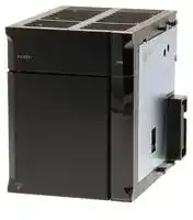
AC Power Supply Unit, 100 VAC to 240 VAC, NJ Series Controller
- Manufacturer: OMRON INDUSTRIAL AUTOMATION
- Product type: Controller Accessories
- SVHC: To Be Advised
- Product Range: NJ Series
- Current Rating: 6A
| Delivery and price | |
|---|---|
| Units per pack | 1 |
| Price | 440.65 € |
| Current stock | 10+ |
| Lead time | 30 days |
**NJ-Series Power Supply Unit NJ-PA/PD** CSM_NJ-PA_PD_DS_E_1_2 ## **Powerful power supply unit to supply stable power to the NJ-series controller.** Stable power supply is available from the NJ-series CPU Unit to each I/O Unit via the dedicated bus. Lineups are provided for AC and DC input types with 30 W output. **==> picture [47 x 7] intentionally omitted <==** **----- Start of picture text -----**<br> NJ-PD3001<br>**----- End of picture text -----**<br> ## **Features** - AC input type (100 to 240 VAC)/DC input type (24 VDC) with 30 W output allows power supply to large-scale configurations. - Operating output contact indicates the CPU operation status (available in all models). ## **Ordering Information** ## **International Standards** - The standards are abbreviated as follows: U: UL, U1: UL(Class I Division 2 Products for Hazardous Locations), C: CSA, UC: cULus, UC1: cULus (Class I Division 2 Products for Hazardous Locations), CU: cUL, N: NK, L: Lloyd, and CE: EC Directives. - Contact your OMRON representative for further details and applicable conditions for these standards. ## **Power Supply Units** |**Product Name**|**Product Name**|**Power**<br>**supply**<br>**voltage**<br>P~~PP~~|**Output**<br>**current**<br>~~PP~~|**Output**<br>**current**<br>~~PP~~|**Output**<br>**capacity**<br>~~rrr~~|**Options**<br>~~rrr~~|**Options**<br>~~rrr~~|**Options**<br>~~rrr~~|**Model**<br>~~rrr~~|**Standards**| |---|---|---|---|---|---|---|---|---|---|---| ||||**5-VDC**<br>**output**<br>**capacity**<br>~~PP~~|**24-VDC**<br>**output**<br>**capacity**<br>~~PP ~~|**Total power**<br>**consumption**<br> ~~rrr~~|**24-VDC**<br>**service**<br>**power**<br>**supply**<br>~~rrr~~|**RUN**<br>**output**<br>~~rrr~~|**Maintenance**<br>**forecast**<br>**monitor**<br>~~rrr~~||| |**AC Power**<br>**Supply Unit**|i~~s;~~|100 to 240<br>VAC<br>~~s;~~|6.0 A|1.0 A|30 W|No|Yes|No|**NJ-PA3001**<br>~~_~~|UC1, N, L,<br>CE| |**DC Power**<br>**Supply Unit**||24 VDC<br>~~s;~~|||||||**NJ-PD3001**<br>~~_~~|| ## **Accessories** There is no accessory for the NJ-series Power Supply Unit. Sysmac is a trademark or registered trademark of OMRON Corporation in Japan and other countries for OMRON factory automation products. Other company names and product names in this document are the trademarks or registered trademarks of their respective companies. **1** **NJ-PA/PD** ## **General Specification** |**Item**|**Specifications**|**Specifications**| |---|---|---| |**Model**|NJ-PA3001|NJ-PD3001| |**Supply voltage**|100 to 240 VAC (wide-range), 50/60 Hz|24 VDC| |**Operating voltage and**<br>**frequency ranges**|85 to 264 VAC, 47 to 63 Hz|19.2 to 28.8 VDC| |**Power consumption**|120 VA max.|60 W max.| |**Inrush current*1**|At 100 VAC:<br>20 A/8 ms max. for cold start at room temperature<br>At 200 VAC:<br>40 A/8 ms max. for cold start at room temperature|At 24 VDC:<br>30 A/20 ms max. for cold start| |**Output capacity*2**|5 VDC, 6.0 A (including supply to CPU Unit using CPU Rack)<br>5 VDC, 6.0 A (using Expansion Rack)<br>24 VDC, 1.0 A<br>Total: 30 W max.|| |**Output terminal**<br>**(service supply)**|Not provided|| |**RUN output*3**|Contact configuration: SPST-NO<br>Switch capacity: 250 VAC, 2 A (resistive load)<br>120 VAC, 0.5 A (inductive load), 24 VDC, 2A (resistive load)|| |**Replacement notification**<br>**function**|Not provided|| |**Insulation resistance*4**|20 MΩmin.<br>(at 500 VDC) between AC external and GR terminals|20 MΩmin.<br>(at 500 VDC) between DC external and GR terminals| |**Dielectric**<br>**strength*4*5**|2,300 VAC 50/60 Hz for 1 min between AC external and GR<br>terminals<br>Leakage current: 10 mA max.|1,000 VAC 50/60 Hz for 1 min between DC external and GR<br>terminals<br>Leakage current: 10 mA max.| |**Noise immunity**|2 kV on power supply line (Conforms to IEC 61000-4-4.)|| |**Vibration resistance**|5 to 8.4 Hz, 3.5-mm amplitude, 8.4 to 150 Hz, acceleration: 9.8 m/s2in X, Y, and Z directions for 100 min (Time coefficient: 10 min ×<br>coefficient factor 10 = total time 100 min) (according to IEC 60068-2-6)|| |**Shock resistance**|147 m/s23 times each in X, Y, and Z directions (Relay Output Unit: 100 m/s2) (according to IEC 60068-2-27)|| |**Ambient operating**<br>**temperature**|0 to 55°C|| |**Ambient operating humidity**|10% to 90% (with no condensation)|| |**Atmosphere**|Must be free from corrosive gases.|| |**Ambient storage**<br>**temperature**|-20 to 75°C|| |**Grounding**|Less than 100Ω|| |**Enclosure**|Mounted in panel|| |**Weight**|470 g max.|490 g max.| |**CPU Rack dimensions**|174.7 to 484.7 × 90 × 90 mm (W × D × H) (not including cables)<br>W = 70 (Power Supply Unit) + 90 (CPU Unit) + 20 × n + 31 × m + 14.7 (end cover)<br>n is the number of 32-point I/O Units or I/O Control Units and m is the number of other Units.|| |**Safety measures**|Conforms to cULus, EC Directives, NK and LR.|| - ***1.** The AC and DC values above are given for a cold start, and the AC values are at room temperature. The AC inrush control circuit uses a thermistor element with a low-temperature current control characteristic. If the ambient temperature is high or the Controller is hot-started, the thermistor will not be sufficiently cool, and the inrush current given in the table may be exceeded by up to twice the given value. The DC inrush control circuit uses a capacitor-charging delay circuit. If the power is OFF for only a short time for a hot-start, the capacitor will not sufficiently discharge and the inrush current given in the table may be exceeded by up to twice the given value. An inrush current of approximately 4 A may occur and continue for 1 s when the power is turned ON. When selecting fuses, breakers, and external DC power supply devices for external circuits, allow sufficient margin in shut-off performance. - ***2.** Internal components in the Power Supply Unit will deteriorate or be damaged if the Power Supply Unit is used for an extended period of time exceeding the power supply output capacity or if the outputs are shorted. - ***3.** Supported only when mounted to CPU Rack. - ***4.** The tests can also be performed with the LG terminal and GR terminal connected to each other. - ***5.** Change the applied voltage gradually using the adjuster on the Tester. If the full dielectric strength voltage is applied or turned OFF using the switch on the Tester, the generated impulse voltage may damage the Power Supply Unit. **2** **NJ-PA/PD** **External Interface** ## **NJ-PA3001** ## **NJ-PD3001** **==> picture [294 x 362] intentionally omitted <==** **----- Start of picture text -----**<br> POWER Indicator<br>(PWR LED)<br>AC input Connector<br>LG<br>GR<br>RUN output<br>POWER Indicator<br>(PWR LED)<br>+ (DC input)<br>Connector<br>– (DC input)<br>LG<br>GR<br>RUN output<br>**----- End of picture text -----**<br> ## **AC Input** Supply 100 to 240 VAC (allowable: 85 to 264 VAC). The NJ-PA3001 has a wide input range, so it does not have voltage switching terminals. ## **DC Input** Supply 24 VDC (allowable: 19.2 to 28.8 VDC.) ## **LG** Ground to a resistance of 100 Ω or less to increase noise resistance and avoid electric shock. ## **GR** Ground to a resistance of 100 Ω or less to avoid electric shock. ## **RUN Output** The internal contacts for the RUN output turn ON when the CPU Unit is in RUN status. **3** **NJ-PA/PD** ## **Wiring** ## � **About Power Supply** For AC/DC power supply Recommended wire AWG 14 to 20 diameter (Cross section 0.517 to 2.08 mm[2] ) ## For grounding wire Recommended wire 2 mm[2] or thicker diameter ## � **Crimp Terminals** The terminals on the Power Supply Unit are M4, self-raising terminals with screws. Crimp Terminals for AC Power Supplies **==> picture [208 x 139] intentionally omitted <==** **----- Start of picture text -----**<br> 7 mm max.<br>Crimp Terminals for DC Power Supplies<br>7 mm max. 7 mm max.<br>Crimp terminal for the grounding wire<br>7 mm max. 7 mm max.<br>**----- End of picture text -----**<br> ## **Precautions for Use** ## **Compatible CPU Models** NJ-PA3001/NJ-PD3001 are dedicated for NJ-series. Please make sure to use NJ-PA3001/NJ-PD3001 for all products including NJ-series CPU rack and expansion rack. ## **Power Supply Units Current Consumption** ## **Checking Current Consumption and Power Consumption** After selecting a Power Supply Unit based on considerations such as the power supply voltage, calculate the current and power requirements for each Rack. Condition 1: Current Requirements There are two voltage groups for internal power consumption: 5 V and 24 V. Current consumption at 5 V (internal logic power supply) Current consumption at 24 V (relay driving power supply) Condition 2: Power Requirements For each Rack, the upper limits are determined for the current and power that can be provided to the mounted Units. Design the system so that the total current consumption for all the mounted Units does not exceed the maximum total power or the maximum current supplied for the voltage groups shown in the following tables. The maximum current and total power supplied for CPU Racks and Expansion Racks according to the Power Supply Unit model are shown below. **Note: 1.** For CPU Racks, include the CPU Unit current and power consumption in the calculations. When expanding, also include the current and power consumption of the I/O Control Unit in the calculations. **2.** For Expansion Racks, include the I/O Interface Unit current and power consumption in the calculations. |**Power**<br>**Supply**<br>**Units**|**Max. current supplied**|**Max. current supplied**|**Max. current supplied**|**(C)**<br>**Max. total**<br>**power**<br>**supplied**| |---|---|---|---|---| ||**(A) 5-VDC CPU**<br>**Racks***|**(A)5-VDC**<br>**Expansion**<br>**Rack**|**(B) 24 VDC**|| |**NJ-PA3001**|6.0 A|6.0 A|1.0 A|30 W| |**NJ-PD3001**|6.0 A|6.0 A|1.0 A|30 W| Conditions 1 and 2 below must be satisfied. Condition 1: Maximum Current - (1) Total Unit current consumption at 5 V ≤ (A) value - (2) Total Unit current consumption at 24 V ≤ (B) value - Condition 2: Maximum Power - (1) × 5 V + (2) × 24 V ≤ (C) value > ***** Including supply to the CPU Unit. **4** **NJ-PA/PD** ## **Example: Calculating Total Current and Power Consumption** Example: When the Following Units are Mounted to a NJ-Series CPU Rack Using a NJ-PA3001 Power Supply Unit |**Unit type**|**Model**|**Quantity**|**Voltage group**|**Voltage group**| |---|---|---|---|---| ||||**5 V**|**24 V**| |CPU Unit|NJ501-1500|1|1.90 A|-| |I/O Control Unit|CJ1W-IC101|1|0.02 A|-| |Basic I/O Units (Input Units)|CJ1W-ID211|2|0.08 A|-| ||CJ1W-ID231|2|0.09 A|-| |Basic I/O Units (Output Units)|CJ1W-OC201|2|0.09 A|0.048 A| |Special I/O Unit|CJ1W-DA041|1|0.12 A|-| |CPU Bus Unit|CJ1W-SCU22|1|0.28 A|-| |Current consumption|Total||1.9 A+0.02 A+0.08 A ×<br>2+0.09 A × 2+0.09 A ×<br>2+0.12 A+0.28|0.048 A × 2| ||Result||2.84 A (≤6.0 A)|0.096 A (≤1.0 A)| |Power consumption|Total||2.84 × 5 V = 14.2 W|0.096 A × 24 V = 2.3 W| ||Result||14.2 W + 2.3 W = 16.5 W (≤30 W)|| ## **Using the Sysmac Studio to Display Current Consumption and Width** CPU Rack and Expansion Rack current consumption and width can be displayed by selecting _**CPU/Expansion Racks**_ from the _**Configurations and Setup**_ in the Multiview Explorer. If the capacity of the Power Supply Unit is exceeded, an error icon is displayed in the power supply unit of a corresponding rack. For details, refer to Sysmac Studio Operation manual (W504). **5** **NJ-PA/PD** **Dimensions** **(Unit: mm)** ## **NJ-PA3001** ## **NJ-PD3001** **==> picture [343 x 411] intentionally omitted <==** **----- Start of picture text -----**<br> 90<br>90 70<br>90<br>90 70<br>**----- End of picture text -----**<br> ## **Related Manuals** |**Manual name**|**Cat. No.**|**Model numbers**|**Application**|**Description**| |---|---|---|---|---| |NJ-series CPU Unit<br>Hardware User’s Manual|W500|NJ501-**@@@@**|Learning the basic<br>specifications of the NJ-series<br>CPU Units, including<br>introductory information,<br>designing, installation, and<br>maintenance. Mainly<br>hardware information is<br>provided.|An introduction to the entire NJ-series system is<br>provided along with the following information on<br>a Controller built with an NJ501 CPU Unit.<br>• Features and system configuration<br>• Introduction<br>• Part names and functions<br>• General specifications<br>• Installation and wiring<br>• Maintenance and inspection<br>Use this manual together with the_NJ-series_<br>_CPU Unit Software User’s Manual_(Cat. No.<br>W501).| **6** ## **Read and Understand This Catalog** Please read and understand this catalog before purchasing the products. Please consult your OMRON representative if you have any questions or comments. ## **Warranty and Limitations of Liability** - **WARRANTY** OMRON's exclusive warranty is that the products are free from defects in materials and workmanship for a period of one year (or other period if specified) from date of sale by OMRON. OMRON MAKES NO WARRANTY OR REPRESENTATION, EXPRESS OR IMPLIED, REGARDING NON-INFRINGEMENT, MERCHANTABILITY, OR FITNESS FOR PARTICULAR PURPOSE OF THE PRODUCTS. ANY BUYER OR USER ACKNOWLEDGES THAT THE BUYER OR USER ALONE HAS DETERMINED THAT THE PRODUCTS WILL SUITABLY MEET THE REQUIREMENTS OF THEIR INTENDED USE. OMRON DISCLAIMS ALL OTHER WARRANTIES, EXPRESS OR IMPLIED. **==> picture [479 x 33] intentionally omitted <==** **----- Start of picture text -----**<br> LIMITATIONS OF LIABILITY<br>OMRON SHALL NOT BE RESPONSIBLE FOR SPECIAL, INDIRECT, OR CONSEQUENTIAL DAMAGES, LOSS OF PROFITS OR COMMERCIAL LOSS<br>IN ANY WAY CONNECTED WITH THE PRODUCTS, WHETHER SUCH CLAIM IS BASED ON CONTRACT, WARRANTY, NEGLIGENCE, OR STRICT<br>LIABILITY.<br>**----- End of picture text -----**<br> In no event shall the responsibility of OMRON for any act exceed the individual price of the product on which liability is asserted. IN NO EVENT SHALL OMRON BE RESPONSIBLE FOR WARRANTY, REPAIR, OR OTHER CLAIMS REGARDING THE PRODUCTS UNLESS OMRON'S ANALYSIS CONFIRMS THAT THE PRODUCTS WERE PROPERLY HANDLED, STORED, INSTALLED, AND MAINTAINED AND NOT SUBJECT TO CONTAMINATION, ABUSE, MISUSE, OR INAPPROPRIATE MODIFICATION OR REPAIR. ## **Application Considerations** **==> picture [508 x 457] intentionally omitted <==** **----- Start of picture text -----**<br> SUITABILITY FOR USE<br>OMRON shall not be responsible for conformity with any standards, codes, or regulations that apply to the combination of products in the customer's<br>application or use of the products.<br>At the customer's request, OMRON will provide applicable third party certification documents identifying ratings and limitations of use that apply to the<br>products. This information by itself is not sufficient for a complete determination of the suitability of the products in combination with the end product,<br>machine, system, or other application or use.<br>The following are some examples of applications for which particular attention must be given. This is not intended to be an exhaustive list of all possible<br>uses of the products, nor is it intended to imply that the uses listed may be suitable for the products:<br> Outdoor use, uses involving potential chemical contamination or electrical interference, or conditions or uses not described in this catalog.<br> Nuclear energy control systems, combustion systems, railroad systems, aviation systems, medical equipment, amusement machines, vehicles,<br>safety equipment, and installations subject to separate industry or government regulations.<br> Systems, machines, and equipment that could present a risk to life or property.<br>Please know and observe all prohibitions of use applicable to the products.<br>NEVER USE THE PRODUCTS FOR AN APPLICATION INVOLVING SERIOUS RISK TO LIFE OR PROPERTY WITHOUT ENSURING THAT THE<br>SYSTEM AS A WHOLE HAS BEEN DESIGNED TO ADDRESS THE RISKS, AND THAT THE OMRON PRODUCTS ARE PROPERLY RATED AND<br>INSTALLED FOR THE INTENDED USE WITHIN THE OVERALL EQUIPMENT OR SYSTEM.<br>PROGRAMMABLE PRODUCTS<br>OMRON shall not be responsible for the user's programming of a programmable product, or any consequence thereof.<br>Disclaimers<br>CHANGE IN SPECIFICATIONS<br>Product specifications and accessories may be changed at any time based on improvements and other reasons.<br>It is our practice to change model numbers when published ratings or features are changed, or when significant construction changes are made.<br>However, some specifications of the products may be changed without any notice. When in doubt, special model numbers may be assigned to fix or<br>establish key specifications for your application on your request. Please consult with your OMRON representative at any time to confirm actual<br>specifications of purchased products.<br>DIMENSIONS AND WEIGHTS<br>Dimensions and weights are nominal and are not to be used for manufacturing purposes, even when tolerances are shown.<br>PERFORMANCE DATA<br>Performance data given in this catalog is provided as a guide for the user in determining suitability and does not constitute a warranty. It may represent the<br>result of OMRON’s test conditions, and the users must correlate it to actual application requirements. Actual performance is subject to the OMRON<br>Warranty and Limitations of Liability.<br>ERRORS AND OMISSIONS<br>The information in this document has been carefully checked and is believed to be accurate; however, no responsibility is assumed for clerical,<br>typographical, or proofreading errors, or omissions.<br>2011.12<br>In the interest of product improvement, specifications are subject to change without notice.<br>**----- End of picture text -----**<br> ## **OMRON Corporation Industrial Automation Company** **http://www.ia.omron.com/** (c)Copyright OMRON Corporation 2011 All Right Reserved.
Updated at April 22, 2026
With a legacy spanning over 80 years, Omron Industrial Automation is a globally recognized leader in the manufacture of advanced industrial control and automation components. Renowned for their reliability and engineering excellence, Omron delivers comprehensive solutions that enhance efficiency, machine safety, and precision across a wide range of manufacturing environments. Our extensive portfolio of Omron products is heavily focused on their industry-leading sensing and switching technologies. We offer a vast selection of sensors, excelling specifically in high-performance proximity sensors, light sensors, and temperature sensors. Complementing this range are robust switching solutions, featuring a deep inventory of power relays, solid-state relays, safety relays, and essential relay accessories designed for demanding operational requirements. Beyond sensing and switching, Omron is highly regarded for its precision automation and process control equipment. Our selection features highly accurate temperature controllers, versatile process controllers, and sophisticated panel displays and instrumentation. To support these fundamental systems, we also supply dependable Omron power supplies, notably AC/DC converters, alongside vital connectivity components like DIN rail terminal blocks to ensure secure, efficient, and complete industrial setups.
About Novapart
Novapart is a B2B electronic component broker specialising in stock shortages and cost reduction. We source hard-to-find parts and identify compliant alternatives across a catalogue of 410,000+ components from 500+ manufacturers.
Learn more →Stock Shortage Specialist
When a component is unavailable, discontinued or has an unacceptable lead time, we tap into our network of vetted European and Asian distributors to source what you need — without compromising on quality or traceability.
Request a quote →Compliant Alternatives
We identify pin-to-pin, electrically equivalent substitutes that meet the same certifications (RoHS, AEC-Q100, REACH) as your original specification — validated against datasheets, not just part numbers. Often at a lower cost.
BOM Analysis service →