


NC4DJPDC24V
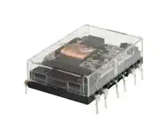
Power Relay, 4PDT, 24 VDC, 5 A, NC Series, Through Hole, Non Latching
- Manufacturer: PANASONIC
- Product type: Power Relays
- SVHC: No SVHC (25-Jun-2025)
- Coil Type: Non Latching
- Coil Voltage: 24VDC
- Product Range: NC Series
- Relay Mounting: Through Hole
- Coil Resistance: 800ohm
- Contact Current: 5A
- Relay Terminals: PC Pin
- Contact Material: Silver Nickel Gold
- Contact Voltage VAC: -
- Contact Voltage VDC: 30V
- Contact Configuration: 4PDT
| Delivery and price | |
|---|---|
| Units per pack | 20 |
| Price | 17.12 € |
| Current stock | 10+ |
| Lead time | 30 days |
## Power Relays ( Over 2 A ) NC RELAYS

Product Catalog

**==> picture [503 x 408] intentionally omitted <==**

2023.6

Power Relays ( Over 2 A )

## NC RELAYS

## Transistor drive, 2 Form C/4 Form C, 5 A Slim power relays

**==> picture [474 x 195] intentionally omitted <==**

**----- Start of picture text -----**<br>
Protective construction:Dust cover type/Sealed type CO FEATURES<br>25.4 25.4 ●Flat type: profile 10.9 mm<br>10.9 Slim type: width 11.2 mm<br>10.9<br>●Twin ( bifurcated ) contact<br>●Plug-in terminal/PC board terminal<br>NC4 Flat type NC2 Flat type<br>(PC board type) (PC board type) ●Sockets and terminal sockets are available<br>11.2<br>11.2<br>TYPICAL APPLICATIONS<br>27.8<br>27.8 ●Electric power equipment<br>●Industrial equipment<br>●Measuring devices<br>NC4 Slim type NC2 Slim type<br>(Plug-in type) (PC board type)<br>(Unit:mm)<br>25.4<br>38.1<br>25.4<br>38.1<br>**----- End of picture text -----**<br>


## ORDERING INFORMATION ( PART NO. : Ordering part number for Japanese market )

## **AW 8**

Terminal shape Contact arrangement Rated coil voltage(DC) Protective construction 2:Slim type, Plug-in terminal 1:2 Form C Single side stable Part No. 0 1 2 3 4 8 9 Nil: Dust cover type 4:Slim type, PC board terminal 4:4 Form C Single side stable ~~+~~ Rated coil voltage(V) 6 12 24 48 100 3 5 60:Sealed type 8:Flat type, PC board terminal ~~-~~

**==> picture [511 x 15] intentionally omitted <==**

**----- Start of picture text -----**<br>
LT ORDERING INFORMATION ( TYPE NO. : Ordering part number for non Japanese market )<br>**----- End of picture text -----**<br>


**NC D** Protective construction Relay shape Operating function Rated coil voltage(DC) Nil:Dust cover type Nil:Slim type Nil:Single side stable 3, 5, 6, 12, 24, 48, 100V EB:Sealed type J :Flat type Contact arrangement Contact characteristics Terminal shape 2:2 Form C D:Twin(bifurcated)contact Nil:Plug-in type 4:4 Form C P :PC board type

Panasonic Industry Co., Ltd. Electromechanical Control Business Division industry.panasonic.com

ASCTB12E   202306

ー 1 ー © Panasonic Industry Co., Ltd. 2023

Power Relays ( Over 2 A ) NC RELAYS

## TYPES

" Type No. " is ordering part number for non Japanese market. " Part No. " is ordering part number for Japanese market.

## ■Dust cover type

- ●Flat type

**==> picture [511 x 195] intentionally omitted <==**

**----- Start of picture text -----**<br>
PC board terminal Standard packing<br>Contact  Rated coil<br>Inner  Outer<br>arrangement voltage Type No. Part No. carton carton<br>  3 V DC NC2D-JP-DC3V AW8818<br>  5 V DC NC2D-JP-DC5V AW8819<br>  6 V DC NC2D-JP-DC6V AW8810<br>2 Form C  12 V DC NC2D-JP-DC12V AW8811<br> 24 V DC NC2D-JP-DC24V AW8812<br> 48 V DC NC2D-JP-DC48V AW8813<br>100 V DC NC2D-JP-DC100V AW8814<br>20 pcs. 200 pcs.<br>  3 V DC NC4D-JP-DC3V AW8848<br>  5 V DC NC4D-JP-DC5V AW8849<br>  6 V DC NC4D-JP-DC6V AW8840<br>4 Form C  12 V DC NC4D-JP-DC12V AW8841<br> 24 V DC NC4D-JP-DC24V AW8842<br> 48 V DC NC4D-JP-DC48V AW8843<br>100 V DC NC4D-JP-DC100V AW8844<br>**----- End of picture text -----**<br>


## ●Slim type

**==> picture [511 x 195] intentionally omitted <==**

**----- Start of picture text -----**<br>
Plug-in terminal PC board terminal Standard packing<br>Contact  Rated coil<br>Inner  Outer<br>arrangement voltage Type No. Part No. Type No. Part No. carton carton<br>  3 V DC NC2D-DC3V AW8218 NC2D-P-DC3V AW8418<br>  5 V DC NC2D-DC5V AW8219 NC2D-P-DC5V AW8419<br>  6 V DC NC2D-DC6V AW8210 NC2D-P-DC6V AW8410<br>2 Form C  12 V DC NC2D-DC12V AW8211 NC2D-P-DC12V AW8411<br> 24 V DC NC2D-DC24V AW8212 NC2D-P-DC24V AW8412<br> 48 V DC NC2D-DC48V AW8213 NC2D-P-DC48V AW8413<br>100 V DC NC2D-DC100V AW8214 NC2D-P-DC100V AW8414<br>20 pcs. 200 pcs.<br>  3 V DC NC4D-DC3V AW8248 NC4D-P-DC3V AW8448<br>  5 V DC NC4D-DC5V AW8249 NC4D-P-DC5V AW8449<br>  6 V DC NC4D-DC6V AW8240 NC4D-P-DC6V AW8440<br>4 Form C  12 V DC NC4D-DC12V AW8241 NC4D-P-DC12V AW8441<br> 24 V DC NC4D-DC24V AW8242 NC4D-P-DC24V AW8442<br> 48 V DC NC4D-DC48V AW8243 NC4D-P-DC48V AW8443<br>100 V DC NC4D-DC100V AW8244 NC4D-P-DC100V AW8444<br>**----- End of picture text -----**<br>


## ■Sealed type

- ●Flat type

**==> picture [511 x 195] intentionally omitted <==**

**----- Start of picture text -----**<br>
PC board terminal Standard packing<br>Contact  Rated coil<br>Inner  Outer<br>arrangement voltage Type No. Part No. carton carton<br>  3 V DC NC2EBD-JP-DC3V AW881860<br>  5 V DC NC2EBD-JP-DC5V AW881960<br>  6 V DC NC2EBD-JP-DC6V AW881060<br>2 Form C  12 V DC NC2EBD-JP-DC12V AW881160<br> 24 V DC NC2EBD-JP-DC24V AW881260<br> 48 V DC NC2EBD-JP-DC48V AW881360<br>100 V DC NC2EBD-JP-DC100V AW881460<br>20 pcs. 200 pcs.<br>  3 V DC NC4EBD-JP-DC3V AW884860<br>  5 V DC NC4EBD-JP-DC5V AW884960<br>  6 V DC NC4EBD-JP-DC6V AW884060<br>4 Form C  12 V DC NC4EBD-JP-DC12V AW884160<br> 24 V DC NC4EBD-JP-DC24V AW884260<br> 48 V DC NC4EBD-JP-DC48V AW884360<br>100 V DC NC4EBD-JP-DC100V AW884460<br>**----- End of picture text -----**<br>


Panasonic Industry Co., Ltd. Electromechanical Control Business Division industry.panasonic.com

ASCTB12E   202306

ー 2 ー

Panasonic Industry Co., Ltd. 2023

Power Relays ( Over 2 A ) NC RELAYS

## ●Slim type

**==> picture [511 x 203] intentionally omitted <==**

**----- Start of picture text -----**<br>
Plug-in terminal PC board terminal Standard packing<br>Contact  Rated coil<br>Inner  Outer<br>arrangement voltage Type No. Part No. Type No. Part No. carton carton<br>  3 V DC NC2EBD-DC3V AW821860 NC2EBD-P-DC3V AW841860<br>  5 V DC NC2EBD-DC5V AW821960 NC2EBD-P-DC5V AW841960<br>  6 V DC NC2EBD-DC6V AW821060 NC2EBD-P-DC6V AW841060<br>2 Form C  12 V DC NC2EBD-DC12V AW821160 NC2EBD-P-DC12V AW841160<br> 24 V DC NC2EBD-DC24V AW821260 NC2EBD-P-DC24V AW841260<br> 48 V DC NC2EBD-DC48V AW821360 NC2EBD-P-DC48V AW841360<br>100 V DC NC2EBD-DC100V AW821460 NC2EBD-P-DC100V AW841460<br>20 pcs. 200 pcs.<br>  3 V DC NC4EBD-DC3V AW824860 NC4EBD-P-DC3V AW844860<br>  5 V DC NC4EBD-DC5V AW824960 NC4EBD-P-DC5V AW844960<br>  6 V DC NC4EBD-DC6V AW824060 NC4EBD-P-DC6V AW844060<br>4 Form C  12 V DC NC4EBD-DC12V AW824160 NC4EBD-P-DC12V AW844160<br> 24 V DC NC4EBD-DC24V AW824260 NC4EBD-P-DC24V AW844260<br> 48 V DC NC4EBD-DC48V AW824360 NC4EBD-P-DC48V AW844360<br>100 V DC NC4EBD-DC100V AW824460 NC4EBD-P-DC100V AW844460<br>**----- End of picture text -----**<br>


For the sockets, please refer to the " Sockets/DIN terminal sockets ".

## RATING

## ■Coil data

- Operating characteristics such as " Operate voltage " and " Release voltage " are influenced by mounting conditions or ambient temperature, etc.

Therefore, please use the relay within ±5 % of rated coil voltage.

- " Initial " means the condition of products at the time of delivery.

**==> picture [511 x 227] intentionally omitted <==**

**----- Start of picture text -----**<br>
Max.<br>Contact  Rated coil  Operate  Release  Rated operating  Coil resistance Rated  allowable<br>voltage* [1] voltage* [1] current operating<br>arrangement voltage  ( ±10 %, at 20 ℃ )  voltage<br> ( at 20 ℃ )   ( at 20 ℃ )   ( ±10 %, at 20 ℃ )  power  ( at 50 ℃ ) * [2]<br>  3 V DC 120   mA     25   Ω<br>  5 V DC  72   mA     69.4 Ω<br>  6 V DC  60   mA    100   Ω 135 % V of<br>Max. 80 % V  Min. 10 % V  360 mW rated coil<br> 12 V DC  30   mA    400   Ω<br>of rated coil  of rated coil  voltage<br>2 Form C<br> 24 V DC voltage voltage  15   mA  1,600   Ω<br> 48 V DC  ( Initial )   ( Initial )    7.5 mA  6,400   Ω<br>110 %V of<br>100 V DC   7.4 mA 13,500   Ω 740 mW rated coil<br>voltage<br>  3 V DC 240   mA     12.5 Ω<br>  5 V DC 144   mA     34.7 Ω<br>  6 V DC Max. 80 % V ofrated coil  Min. 10 % V of rated coil  120   mA     50   Ω 720 mW 110 % V of<br>4 Form C  12 V DC  60   mA    200   Ω rated coil<br>voltage voltage<br> 24 V DC  ( Initial )   ( Initial )   30   mA    800   Ω voltage<br> 48 V DC  15   mA  3,200   Ω<br>100 V DC   7.4 mA 13,500   Ω 740 mW<br>**----- End of picture text -----**<br>


*1: Square, pulse drive

- *2: At 20℃ ( Sealed type )

Panasonic Industry Co., Ltd. Electromechanical Control Business Division industry.panasonic.com

ASCTB12E   202306

ー 3 ー

Panasonic Industry Co., Ltd. 2023

Power Relays ( Over 2 A ) NC RELAYS

## ■Specifications

**==> picture [511 x 379] intentionally omitted <==**

**----- Start of picture text -----**<br>
Item Specifications<br>Contact<br>2 Form C 4 Form C<br>arrangement<br>Contact resistance<br>( initial ) Max. 50 mΩ ( by voltage drop 6 V DC 1 A )<br>Contact material Au-clad, AgNi type<br>Contact rating Dust cover: 5 A 250 V AC, 5 A 30 V DC Dust cover: 4 A 250 V AC, 5 A 30 V DC<br>( resistive ) Sealed       : 3 A 250 V AC, 5 A 30 V DC Sealed       : 2 A 250 V AC, 5 A 30 V DC<br>Contact data Max. switching  Dust cover: 1,250 VA, 150 W Dust cover: 1,000 VA, 150 W<br>power ( resistive ) Sealed       :   750 VA, 150 W Sealed       :   500 VA, 150 W<br>Max. switching<br>250 V AC, 220 V DC<br>voltage<br>Max. switching  Dust cover: 5 A ( AC, DC )  Dust cover: 4 A ( AC ), 5 A ( DC )<br>current Sealed       : 3 A ( AC ), 5 A ( DC )  Sealed       : 2 A ( AC ), 5 A ( DC )<br>Min. switching load<br>( reference value )* [1] 100 µA 1 V DC<br>Insulation resistance ( initial ) Min. 100 MΩ ( at 500 V DC, Measured portion is the same as the case of dielectric strength. )<br>Between open<br>contacts 1,000 Vrms for 1 min ( detection current: 10 mA )<br>Dielectric<br>Between contact<br>strength sets 1,000 Vrms for 1 min ( detection current: 10 mA )<br> ( initial )<br>Between contact<br>and coil 2,000 Vrms for 1 min ( detection current: 10 mA )<br>Time  Operate time Max. 20 ms at rated coil voltage ( at 20 ℃, without bounce )<br>characteristics<br>( initial ) Release time Max. 10 ms at rated coil voltage ( at 20 ℃, without bounce, without diode )<br>Shock  Functional 98 m/s [2]  ( half-sine shock pulse: 11 ms, detection time: 10 µs )<br>resistance Destructive 980 m/s [2]  ( half-sine shock pulse: 6 ms )<br>Vibration  Functional 10 to 55 Hz ( at double amplitude of 1 mm, detection time: 10 µs )<br>resistance Destructive 10 to 55 Hz ( at double amplitude of 2 mm )<br>Expected life Mechanical life Min.50 × 10 [6]  ope. ( switching frequency: at 180 times/min )<br>Conditions for  Ambient temperature:  -40 to +70 ℃ ( Max. 48 V DC ),<br>Conditions usage, transport and  -40 to +55 ℃ ( Min. 100 V DC )  Ambient temperature: -40 to +55 ℃<br>storage* [2] Humidity: 5 to 85 % RH ( Avoid icing and condensation )  Humidity: 5 to 85 % RH ( Avoid icing and condensation )<br>Slim type: Approx. 19 g<br>Unit weight Approx. 16 g<br>Flat type : Approx. 18 g<br>**----- End of picture text -----**<br>


- *1:  This value can change due to the switching frequency, environmental conditions, and desired reliability level, therefore it is recommended to check this with the actual load.

- *2:  For ambient temperature, please read " GUIDELINES FOR RELAY USAGE ".

## ■Expected electrical life

Conditions: Resistive load, switching frequency at 20 times/min

**==> picture [511 x 105] intentionally omitted <==**

**----- Start of picture text -----**<br>
Type Switching capacity Number of operations<br>5 A  30 V DC Min. 500 × 10 [3]  ope.<br>Dust cover<br>5 A 250 V AC Min. 100 × 10 [3]  ope.<br>2 Form C<br>5 A  30 V DC Min. 500 × 10 [3]  ope.<br>Sealed<br>3 A 250 V AC Min. 100 × 10 [3]  ope.<br>5 A  30 V DC Min. 500 × 10 [3]  ope.<br>Dust cover<br>4 A 250 V AC Min. 100 × 10 [3]  ope.<br>4 Form C<br>5 A  30 V DC Min. 500 × 10 [3]  ope.<br>Sealed<br>2 A 250 V AC Min. 100 × 10 [3]  ope.<br>**----- End of picture text -----**<br>


Panasonic Industry Co., Ltd. Electromechanical Control Business Division industry.panasonic.com

ASCTB12E   202306

ー 4 ー

Panasonic Industry Co., Ltd. 2023

Power Relays ( Over 2 A ) NC RELAYS

## REFERENCE DATA

## 1-1.  Switching life curve

## 1-2. Switching life curve ( 2 Form C )

## 1-3. Switching life curve ( 4 Form C )

( 2 Form C, 4 Form C )

**==> picture [338 x 335] intentionally omitted <==**

**----- Start of picture text -----**<br>
10,000 5,000<br>30V DC<br>110V DC resistive<br>resistive load 1,000<br>load<br>1,000<br>100 250V AC resistive load<br>220V DC<br>100 resistive load<br>250V AC<br>inductive load<br>10 (pf=0.4)<br>0.1 1.0 10 1 2 3 4 5<br>Contact current(A) Contact current(A)<br>2. Coil temperature characteristics 3-1.  Ambient temperature characteristics<br> ( 2 Form C )<br>Measured portion:Coil inside<br>120<br>5A 3A<br>80<br>5A<br>70 3A 110<br>60<br>50 100 Operate voltage<br>40<br>30 90<br>4c<br>20 2c Release voltage<br>Coil powerconsumption   0.4 0.6 0.8 1.0 1.2 1.4 1.6 1.8W 80<br>Coil applied<br>voltage<br>(MAX. 2c 48V DC) 100 120 140 160 180 200 220%V<br>(MAX. 2c 100V DC )<br>4c all types 100 110 120 130 140 150%V ー40 ー20 0 20 40 60 80<br>Ambient temperature(℃)<br>)410 )410<br>(× (×<br>No. of operations No. of operations<br>(℃)<br>(%)<br>Temperature rise<br>Rate of change<br>**----- End of picture text -----**<br>


3-1.  Ambient temperature characteristics ( 2 Form C )

**==> picture [168 x 335] intentionally omitted <==**

**----- Start of picture text -----**<br>
5,000<br>1,000<br>125V AC<br>inductive load(pf=0.4)<br>100 250V AC resistive load<br>125V AC resistive load<br>250V AC<br>10 inductive load<br>(pf=0.4)<br>1 2 3 4 5<br>Contact current(A)<br>3-2.  Ambient temperature characteristics<br> ( 4 Form C )<br>120<br>110<br>100<br>Operate voltage<br>90<br>80 Release voltage<br>ー40 ー20 0 20 40 60 80<br>Ambient temperature(℃)<br>)410<br>(×<br>No. of operations<br>(%)<br>Rate of change<br>**----- End of picture text -----**<br>


## 3-2.  Ambient temperature characteristics

## 4. Operate time

## 5. Release time

**==> picture [340 x 145] intentionally omitted <==**

**----- Start of picture text -----**<br>
20 5<br>4c 4c<br>18<br>2c 2c<br>16 4<br>14<br>12 3 Max.<br>10<br>Min.<br>8 2 Max.<br>Max. Min.<br>6 Max.<br>4 Min.Min. 1<br>2<br>80 90 100 110 80 90 100 110<br>Coil applied voltage(%V) Coil applied voltage(%V)<br>) )<br>ms ms<br>(Operate time (Release time<br>**----- End of picture text -----**<br>


## 6-1.  Ambient temperature vs Max. applied voltage

- ( 2 Form C: 3 to 48 V DC type )

- 6-2.  Ambient temperature vs Max. applied voltage

   - (2 Form C: 100 V DC type, 4 Form C )

**==> picture [340 x 144] intentionally omitted <==**

**----- Start of picture text -----**<br>
250 250<br>Contact carrying current<br>200 200<br>0A Contact carrying current<br>3A<br>150 150<br>5A 0A<br>3A<br>5A<br>100 100<br>40 50 60 70 30 40 50<br>Ambient temperature(℃) Ambient temperature(℃)<br>) )<br>V V<br>(% (%<br>Max. applied voltage Max. applied voltage<br>**----- End of picture text -----**<br>


Panasonic Industry Co., Ltd. Electromechanical Control Business Division industry.panasonic.com

ASCTB12E   202306

Panasonic Industry Co., Ltd. 2023

ー 5 ー

Power Relays ( Over 2 A ) NC RELAYS

## DIMENSIONS ( Unit: mm )

## ap **CAD** The CAD data of the products with a " CAD " mark can be downloaded from our Website.

## ■Dust cover: Flat type

**==> picture [132 x 9] intentionally omitted <==**

**----- Start of picture text -----**<br>
●PC board terminal: 2 Form C<br>**----- End of picture text -----**<br>


**==> picture [277 x 223] intentionally omitted <==**

**----- Start of picture text -----**<br>
ap CAD External dimensions<br>5.08 5.08 5.08<br>0.8<br>é<br>25.4 10.9 3.5<br>i<br>General tolerance<br>r i t<br>Less than 1mm:±0.2<br>| 0.8 Min. 1mm less than 3mm:±0.3<br>7.62 5.08 7.62 Min. 3mm:±0.5<br>0.4<br>25.4 27.94<br>0.4<br>**----- End of picture text -----**<br>


**==> picture [192 x 181] intentionally omitted <==**

**----- Start of picture text -----**<br>
Recommended  Schematic<br>PC board pattern  ( TOP VIEW )<br> ( BOTTOM VIEW )   ( De-energize )<br>8ーφ1.2 14 13 12 11<br>φ2.8 hole<br>CNLLAIPit 11 12 Te 13 14 2 ー4 &3 5+ 7<br>PitPitPitPitPitPit [ttt][TPT][TPT]  tttTetTettettettetttttttttt tytyyyyyyyyy<br>PEt ttt tet yy<br>PEt@Llele ttTe t [ttt] tet [le!] yyyy<br>7 5 4 2<br>—— 2.54<br>Tolerance ±0.1<br>11<br>×<br>2.54<br>2.54<br>**----- End of picture text -----**<br>


## ●PC board terminal: 4 Form C

**==> picture [505 x 223] intentionally omitted <==**

**----- Start of picture text -----**<br>
External dimensions Recommended  Schematic<br>ap CAD<br>5.08 5.08 5.08 5.08 5.08 5.08 5.08 PC board pattern  ( TOP VIEW )<br>0.8  ( BOTTOM VIEW )   ( De-energize )<br>φ2.8 14ーφ1.2 hole 16 15 14 13 12 11 10 9<br>GoPpSe. weSoe e gaeeee e awa 9 10 11 12 13 14 15 16 pk tye Vel HP<br>ー +<br>a@e Sg ef peeeeeeem OOSSSeeeFETT rT tT rt ery yey ey 1 Pe 2 a 4 5 sy 7 8<br>PET tT rT erty ety ey ey<br>PET tT rT erty ety ey ey<br>PET tT rT erty ety ey ey<br>Pit Try Prt erty yey ey<br>PPT Try Prey yey yey ey<br>Pit Trt trey ere yey yy<br>PPT tT rt rr rT ert yey ey<br>PPT Trt Prete rey ee ey<br>Hele leelete<br>8 7 5 4 2 1<br>38.1 10.9 3.5 2.54<br>—_— Tho Tolerance ±0.1<br>Lia ey General tolerance<br>rr rrG e rtce<br>Less than 1mm:±0.2<br>0.8 Min. 1mm less than 3mm:±0.3<br>5.08 7.62 5.08 7.62 5.08 Min. 3mm:±0.5<br>0.4 11<br>×<br>2.54<br>25.4 27.94<br>0.4<br>.54<br>2<br>**----- End of picture text -----**<br>


Panasonic Industry Co., Ltd. Electromechanical Control Business Division industry.panasonic.com

ASCTB12E   202306

ー 6 ー © Panasonic Industry Co., Ltd. 2023

Power Relays ( Over 2 A ) NC RELAYS

■Dust cover: Slim type ●Plug-in terminal: 2 Form C

**==> picture [461 x 187] intentionally omitted <==**

**----- Start of picture text -----**<br>
ap CAD External dimensions Schematic<br> ( BOTTOM VIEW )<br>eee fl  ( De-energize )<br>11 12 13 14<br>+ ー<br>awe — 7 5 4 2<br>7 2.5 2.5 0.4 a 0.4<br>| 7.62<br>25.4 11.2<br>Perr 5.08 5.08 5.08<br>General tolerance<br>bigs Wale Less than 1mm:±0.2<br>g i o wig 0.8 Min. 1mm less than 3mm:±0.3<br>B 7.62 ES 5.08 7.62 Min. 3mm:±0.5<br>27.8<br>6.1<br>**----- End of picture text -----**<br>


**==> picture [510 x 428] intentionally omitted <==**

**----- Start of picture text -----**<br>
●Plug-in terminal: 4 Form C<br>Yd) CAD External dimensions Schematic<br> ( BOTTOM VIEW )<br>(De-energize)<br>9 10 11 12 13 14 15 16<br>+ ー<br>8 7 5 4 2 1<br>ae E 2.5 E T 2.5 E | 0.4 | 0.4<br>| iu " 1 7.62<br>38.1 11.2<br>ccc 5.08 5.08 5.08 5.08 5.08 5.08 5.08<br>9|)| 1 0 1 12 13 || 14 q 16<br>General tolerance<br>Less than 1mm:±0.2<br>r ag a a 0.8 la e Min. 1mm less than 3mm:±0.3<br>5.08 7.62 5.08 7.62 5.08 Min. 3mm:±0.5<br>L t [Ee]<br>●PC board terminal: 2 Form C<br>ap CAD External dimensions Recommended Schematic<br>PC board pattern   ( BOTTOM VIEW )<br>( BOTTOM VIEW )   ( De-energize )<br>11 12 13 14<br>φ2.8 8ーφ1.2 hole<br>11 12 13 14<br>+ ー<br>| ih oe<br>LITLWe iz | NORTOrPeerEe 7 ? 5 a 4 S 2<br>7 5 4 2<br>W o y 0.8 Te 0.2 0.4 T ie l 2.54 T ie Piet TAT<br>| I 7.62 L Tolerance ±0.1<br>25.4 11.2<br>Prt 5.08 5.08 5.08 |<br>1 W211 13 || 14 General tolerance<br>Less than 1mm:±0.2<br>purus<br>Min. 1mm less than 3mm:±0.3<br>7.62 5.08 7.62 Min. 3mm:±0.5<br>L t ld<br>27.8<br>6.1<br>27.8 32.54×<br>.1<br>4 .54<br>2<br>**----- End of picture text -----**<br>


Panasonic Industry Co., Ltd. Electromechanical Control Business Division industry.panasonic.com

ASCTB12E   202306

ー 7 ー © Panasonic Industry Co., Ltd. 2023

Power Relays ( Over 2 A ) NC RELAYS

●PC board terminal: 4 Form C

**==> picture [506 x 184] intentionally omitted <==**

**----- Start of picture text -----**<br>
Ga» CAD External dimensions Recommended Schematic<br>PC board pattern (BOTTOM VIEW)<br>ees<br>Ks@  (BOTTOM VIEW) (De-energize)<br>9 10 11 12 13 14 15 16<br>φ2.8 14ーφ1.2 hole<br>9 10 11 12 13 14 15 16 + ー<br>| i oa PUP) AP PP PP 8 7 a8 5 4 2 1<br>‘Uaae2 LP OeOOoOo}<br>SB | FEES<br>“4 La v , o ESelele@le@lelel<br>8 7 5 4 2 1<br>2.54<br>roy eT 0.8 . | 0.2 0.4 i Tolerance ±0.1<br>7.62<br>38.1 11.2<br>coor 5.08 5.08 5.08 5.08 5.08 5.08 5.08<br>General tolerance<br>as) leap |) 8/4 4 (S)| SL I Ab, Less than 1mm:±0.2<br>Min. 1mm less than 3mm:±0.3<br>a 5.08 7.62 5.08 7.62 5.08 Min. 3mm:±0.5<br>3×<br>27.8 2.54<br>.1<br>4 .54<br>2<br>**----- End of picture text -----**<br>


**==> picture [132 x 21] intentionally omitted <==**

**----- Start of picture text -----**<br>
■Sealed: Flat type<br>●PC board terminal: 2 Form C<br>**----- End of picture text -----**<br>


**==> picture [505 x 449] intentionally omitted <==**

**----- Start of picture text -----**<br>
Ga» CAD External dimensions Recommended Schematic<br>5.08 5.08 5.08 PC board pattern  ( TOP VIEW )<br>0.8  ( BOTTOM VIEW )   ( De-energize )<br>φ2.8 hole8ーφ1.2 14 13 12 11<br>rSOt~CS~SCSY 11 12 13 14 &%<br>ー +<br>| | LT AT eR TS TT ? 5S $<br>| | Peete Poorer 2 4 5 7<br>PEEE  Eee<br>PeEE  ELE<br>PEEE  ELE<br>CEEE  Eee<br>PEEE  Eee<br>PEEE  Eee<br>25.4 10.9 3.5<br>I EEEEEEEEHH<br>id LALIAlLALIA! 7 5 4 2<br>2.54<br>TOT Ee General tolerance ae Tolerance ±0.1<br>Less than 1mm:±0.2<br>| 0.8 Min. 1mm less than 3mm:±0.3<br>7.62 5.08 7.62 Min. 3mm:±0.5<br>●PC board terminal: 4 Form C<br>a» CAD External dimensions Recommended Schematic<br>5.085.085.085.085.085.085.08 PC board pattern  ( TOP VIEW )<br>0.8  ( BOTTOM VIEW )   ( De-energize )<br>φ2.8 14ーφ1.2 hole 16 15 14 13 12 11 10 9<br>9 10 11 12 13 14 15 16<br>ー +<br>oo St WTR LEE fo<br>rt [PO OOO 1 2 4 5 7 8<br>PPEee [eee] Oo |<br>COCE Eee}et 4<br>COCE Eee}<br>COCEEC Eee<br>COCCECEEe eee<br>COC Eee eee]<br>COC]<br>COC]<br>38.1 10.9 3.5 COC]<br>8 7 5 4 2 1<br>— a 2.54 n<br>Tolerance ±0.1<br>General tolerance<br>Less than 1mm:±0.2<br>0.8 PPE TE Min. 1mm less than 3mm:±0.3<br>5.08 7.62 5.08 7.62 5.08 Min. 3mm:±0.5<br>0.4<br>25.4 27.94 11×<br>2.54<br>0.4<br>2.54<br>0.4<br>11<br>25.4 27.94 ×<br>2.54<br>0.4<br>.54<br>2<br>**----- End of picture text -----**<br>


Panasonic Industry Co., Ltd. Electromechanical Control Business Division industry.panasonic.com

ー 8 ー © Panasonic Industry Co., Ltd. 2023

ASCTB12E   202306

Power Relays ( Over 2 A ) NC RELAYS

## ■Sealed: Slim type

●Plug-in terminal: 2 Form C

**==> picture [29 x 11] intentionally omitted <==**

**----- Start of picture text -----**<br>
Ga» CAD<br>**----- End of picture text -----**<br>


**==> picture [320 x 198] intentionally omitted <==**

**----- Start of picture text -----**<br>
External dimensions Schematic<br> ( BOTTOM VIEW )<br> ( De-energize )<br>Dent 0.4<br>11 12 13 14<br>+ ー<br>7 5 4 2<br>_ ~<br>2.5 2.5 0.4 0.4<br>7.62<br>25.4 11.2<br>5.08 5.08 5.08<br>Perr q<br>|<br>General tolerance<br>Less than 1mm:±0.2<br>0.8 Min. 1mm less than 3mm:±0.3<br>B 7.62 ES 5.08 7.62 Min. 3mm:±0.5<br>27.8<br>6.1<br>**----- End of picture text -----**<br>


●Plug-in terminal: 4 Form C a» **CAD**

## External dimensions

**==> picture [345 x 203] intentionally omitted <==**

**----- Start of picture text -----**<br>
Schematic<br>38.1  ( BOTTOM VIEW )<br>Po  ( De-energize )<br>9 10 11 12 13 14 15 16<br>+ ー<br>8 7 5 4 2 1<br>HD 2.5 iI Ul N 2.5 e 0.4 0.4<br>7.62<br>38.9 11.2<br>5.08 5.08 5.08 5.08 5.08 5.08 5.08<br>General tolerance<br>AAA Less than 1mm:±0.2<br>0.8 Min. 1mm less than 3mm:±0.3<br>TEE 5.08 7.62 5.08 7.62 5.08 Min. 3mm:±0.5<br>27.8<br>6.1<br>**----- End of picture text -----**<br>


●PC board terminal: 2 Form C

a» **CAD** External dimensions

**==> picture [398 x 215] intentionally omitted <==**

**----- Start of picture text -----**<br>
External dimensions Recommended Schematic<br>PC board pattern  ( BOTTOM VIEW )<br> ( BOTTOM VIEW )   ( De-energize )<br>Dent 0.4 φ2.8 8ーφ1.2 hole 11 12 13 14<br>11 12 13 14<br>+ ー<br>7 5 4 2<br>7 5 4 2<br>a 2.54<br>Tolerance ±0.1<br>UY UU UY<br>| 0.8 0.2 0.4<br>7.62<br>25.4 11.2<br>5.08 5.08 5.08<br>General tolerance<br>Less than 1mm:±0.2<br>ey<br>Min. 1mm less than 3mm:±0.3<br>7.62 5.08 7.62 Min. 3mm:±0.5<br>3×<br>2.54<br>27.8<br>.54<br>2<br>4.1<br>**----- End of picture text -----**<br>


Panasonic Industry Co., Ltd. Electromechanical Control Business Division industry.panasonic.com

ー 9 ー

ASCTB12E   202306

Panasonic Industry Co., Ltd. 2023

Power Relays ( Over 2 A ) NC RELAYS

●PC board terminal: 4 Form C

**==> picture [510 x 184] intentionally omitted <==**

**----- Start of picture text -----**<br>
ap CAD External dimensions Recommended Schematic<br>38.1 PC board pattern  ( BOTTOM VIEW )<br>po<br> ( BOTTOM VIEW )  ( De-energize )<br>φ2.8 14ーφ1.2 hole 9 10 11 12 13 14 15 16<br>9 10 11 12 13 14 15 16<br>+ ー<br>oy OTOH T ER o me S<br>| OOOO [PEE]  eee 8 7 5 4 2 1<br>RTT<br>UUUUG 8 7 5 PT 4 2 1<br>UU UUUdd 0.8 0.2 0.4 i 2.54 Tolerance ±0.1<br>7.62<br>38.9 11.2<br>5.08 5.08 5.08 5.08 5.08 5.08 5.08<br>General tolerance<br>Less than 1mm:±0.2<br>AAEM Min. 1mm less than 3mm:±0.3<br>LT 5.08 7.62 5.08 7.62 5.08 Min. 3mm:±0.5<br>3×<br>27.8 2.54<br>.1<br>4 .54<br>2<br>**----- End of picture text -----**<br>


## SAFETY STANDARDS

Each standard may be updated at any time, so please check our Website for the latest information.

## ■UL ( Approved )

- ●Dust cover

## 2 Form C

## ●Sealed

## 2 Form C

|File No.|File No.|Contact rating|Operations||File No.|Contact rating|Operations|
|---|---|---|---|---|---|---|---|
|||5 A 250 V AC|100 × 103|||5 A 30 V DC|100 × 103|
|E43028||5 A 30 V DC|100 × 103||E43028|3 A 250 V AC|100 × 103|
|||1⁄10HP 125, 250 V AC|-|||1⁄20HP 125, 250 V AC|-|


## 4 Form C

|File No.|Contact rating|Operations|
|---|---|---|
|E43028|5 A 30 V DC|100 × 103|
||4 A 250 V AC|100 × 103|
||1⁄10HP 125, 250 V AC|-|


## 4 Form C

|File No.|Contact rating|Operations|
|---|---|---|
|E43028|5 A 30 V DC<br>2 A 250 V AC<br>1⁄20HP 125, 250 V AC|100 × 103|
|||100 × 103|
|||-|


## ■CSA ( Approved )

## ●Dust cover

## 2 Form C

|File No.|Contact rating|Operations|
|---|---|---|
|1440474|5 A 250 V AC|100 × 103|
||5 A 30 V DC|100 × 103|
||1⁄10HP 125, 250 V AC|-|


## ●Sealed

## 2 Form C

|File No.|Contact rating|Operations|
|---|---|---|
|1440474|5 A 30 V DC<br>3 A 250 V AC<br>1⁄20HP 125, 250 V AC|100 × 103|
|||100 × 103|
|||-|


## 4 Form C

## 4 Form C

|File No.|File No.|Contact rating|Operations||File No.|Contact rating|Operations|
|---|---|---|---|---|---|---|---|
|||5 A 30 V DC|100 × 103|||5 A 30 V DC|100 × 103|
|1440474||4 A 250 V AC|100 × 103||1440474|2 A 250 V AC|100 × 103|
|||1⁄10HP 125, 250 V AC|-|||1⁄20HP 125, 250 V AC|-|


Panasonic Industry Co., Ltd. Electromechanical Control Business Division industry.panasonic.com

ー 10 ー © Panasonic Industry Co., Ltd. 2023

ASCTB12E   202306

Power Relays ( Over 2 A ) NC RELAYS

## GUIDELINES FOR USAGE ~~Lo~~

## ■ For cautions for use, please read " GUIDELINES FOR RELAY USAGE ".

https://industry.panasonic.com/global/en/products/control/relay/cautions_use

- ■Cautions for usage of NC relay

- Because the NC relay is polarized, the positive ( + ) and negative ( - ) connections to the coil should be done as indicated on the wiring diagram. If connected incorrectly, it may malfunction or fail to operate.

- ●When designing top and bottom view schematic diagrams, note that:

   - 1)  " Top view " wiring diagram is indicated for the flat type because terminals can be seen from above.

**==> picture [36 x 7] intentionally omitted <==**

**----- Start of picture text -----**<br>
TOP VIEW<br>**----- End of picture text -----**<br>


- While NC relays can be used with any transmission-wave current to their operation, due to slight weakening of the force of magnetic attraction, decreased resistance to vibration and shock should be taken into account.

- ●Cautions for close proximity mounting When using slim series in close proximity, mount all relays facing the same direction. Different mounting directions may cause change in the relay characteristics because NC relays are polarized.

**==> picture [57 x 7] intentionally omitted <==**

**----- Start of picture text -----**<br>
Same direction<br>**----- End of picture text -----**<br>


**==> picture [33 x 9] intentionally omitted <==**

**----- Start of picture text -----**<br>
Flat type<br>**----- End of picture text -----**<br>


- 2)  " Bottom view " schematic diagram is indicated for the slim type because terminals cannot be seen from above.

**==> picture [53 x 107] intentionally omitted <==**

**----- Start of picture text -----**<br>
Slim type<br>Sy<br>4<br>BOTTOM VIEW<br>**----- End of picture text -----**<br>


Panasonic Industry Co., Ltd. Electromechanical Control Business Division industry.panasonic.com

ASCTB12E   202306

ー 11 ー

Panasonic Industry Co., Ltd. 2023

Power Relays ( Over 2 A ) NC RELAYS ~~**e** ee~~ reerreer ~~erence ee~~

## Sockets/DIN terminal sockets

**==> picture [217 x 135] intentionally omitted <==**

**----- Start of picture text -----**<br>
NC2 Flat type NC4 Flat type NC2 Slim type<br>socket socket socket<br>< —> ar cy ot<br>ha) | : 1 |<br>NC4 Slim type NC2<br>socket DIN terminal socket<br>**----- End of picture text -----**<br>


## TYPES

|Type|Product name<br>~~e~~|Terminal<br>connection<br>method<br>~~e~~e|Type No.<br>e|Part No.<br>e~~e~~|Main Part No.<br>to be installed<br>~~e~~|Standardpacking|Standardpacking|
|---|---|---|---|---|---|---|---|
|||||||Inner<br>carton<br>~~e~~|Outer<br>carton|
|Flat type socket|NC2- flat type PC board socket<br>~~e~~|PC board<br>~~e~~e|NC2-JPS<br>e|AW4920<br>e~~e~~|AW881 series<br>~~e~~|20 pcs.<br>~~e~~<br>ee|200 pcs.|
||NC4-flat type PC board socket<br>~~e~~|PC board<br>~~e~~e|NC4-JPS<br>e<br>i|AW4940<br>e~~e~~<br>i|AW884 series<br>~~e~~<br>ee|||
|Slim type<br>DIN terminal socket|NC2-DIN terminal socket<br>~~e~~<br>~~L~~|DIN rail<br>~~e~~e<br>~~L~~<br>a|NC2-SFD<br>e<br>~~Lh~~<br>i|AW4928<br>e~~e~~<br>~~h~~<br>i|AW821 series<br>~~e~~<br>~~h~~<br>ee|20 pcs.<br>~~e~~<br>~~h~~<br>ee|100 pcs.|
|Slim type socket|NC2- slim type solderingsocket<br>~~a~~|Solder terminal<br>~~a~~<br>a<br>ee|NC2-SS<br>i <br>~~a~~<br>ee|AW4922<br> i<br>~~a~~<br>ee|AW821 series<br>ee|20 pcs.<br>ee|200 pcs.|
||NC2- slim type PC board socket<br>~~a~~|PC board<br>a<br>~~a~~<br>ee<br>ee|NC2-PS<br>~~a~~<br>ee<br>eeee|AW4924<br>~~a~~<br>ee<br>ee||||
||NC2-slim type wrappingsocket<br>~~a~~|Lead wire<br>ee<br>~~a~~<br>ee<br>a|NC2-WS<br>ee <br>~~a~~<br>eeee<br>ee|AW4926<br> ee<br>~~a~~<br>ee||||
||NC4-slim type solderingsocket<br>~~a~~|Solder terminal<br>ee<br>~~a~~<br>a<br>a|NC4-SS<br>eeee<br>~~a~~<br>ee<br>ee|AW4942<br>ee<br>~~a~~<br>ee|AW824 series|||
||NC4-slim type PC board socket<br>~~a~~|PC board<br>a<br>~~a~~<br>a<br>ee|NC4-PS<br>ee<br>~~a~~<br>ee<br>ee|AW4944<br>~~a~~<br>ee||||
||NC4- slim type wrappingsocket<br>~~a~~|Lead wire<br>a<br>~~a~~<br>ee|NC4-WS<br>ee <br>~~a~~<br>ee|AW4946<br> ee<br>~~a~~||||


## RATING

|Item|Specifications|
|---|---|
|Dielectric strength(initial)|Each between terminals: 2,000 Vrms for 1 min(detection current: 10 mA)|
|Insulation resistance ( initial )|Each between terminals:  Min. 100 MΩ<br> (at 500 V DC,Measuredportion is the same as the case of dielectric strength.)|
|Max. continuous carrying<br>current|Slim type: 5 A 250 V AC<br>Flat type : 5 A 250 V AC|
|Conditions for usage,<br>transport and storage|Ambient temperature:  -50 to +50 ℃ ( AW4924, AW4926, AW4928, AW4944, AW4946 )<br>-40 to +70 ℃ ( AW4920, AW4922, AW4940, AW4942 )<br>Humidity: 5 to 85 % RH(Avoid icingand condensation)|


Panasonic Industry Co., Ltd. Electromechanical Control Business Division industry.panasonic.com

ASCTB12E   202306

ー 12 ー

Panasonic Industry Co., Ltd. 2023

Power Relays ( Over 2 A ) NC RELAYS

## DIMENSIONS ( Unit: mm )

ap **CAD** The CAD data of the products with a " CAD " mark can be downloaded from our Website.

## ■Flat type PC board socket

●NC2 ( AW4920 )

**==> picture [504 x 149] intentionally omitted <==**

**----- Start of picture text -----**<br>
ap CAD External dimensions Terminal portion Recommended<br>dimensions PC board pattern<br>15.24<br>2ーφ3.5 4.7 5.08 3.9 φ2.8 8ーφ1.2<br>0.5max 11 12 13 14<br>ry 1 |<br>10.16<br>og o/® i l s pH<br>General tolerance ±0.5 7 5 4 2<br>2.54<br>$ A ) I (—)<br>25.4 14.8 5.08 Tolerance ±0.1<br>BS = 20.32<br>General tolerance ±0.5<br>0.4 11<br>0.9 ×<br>2.54<br>34.9 27.94<br>Approx. 44.3<br>.54<br>2<br>**----- End of picture text -----**<br>


**==> picture [504 x 179] intentionally omitted <==**

**----- Start of picture text -----**<br>
●NC4 ( AW4940 )<br>ea» CAD External dimensions Terminal portion Recommended<br>35.56 dimensions PC board pattern<br>25.4<br>15.24 3.9 φ2.8 14ーφ1.2<br>20.32 2ーφ3.5 4.7 5.08 0.5max a 9 10 11 12 13 14 15 16<br>af} st I ae: HSI<br>| ; T | may t LT EERE  TTT EEE TTT t ye tery ey |<br>OTe O>+; +o T n e Hatettotptea<br>8 7 5 4 2 1<br>| | | | LI | fe TT 2.54 !<br>Tolerance ±0.1<br>f — ) (| General tolerance ±0.5<br>40 14.8 5.08<br>20.32<br>30.48<br>a n i aal<br>General tolerance ±0.5<br>0.4<br>11<br>×<br>0.9 2.54<br>34.9 27.94<br>Approx. 44.3<br>.54<br>2<br>**----- End of picture text -----**<br>


## ■Slim type DIN terminal socket

●NC2 ( AW4928 )

**==> picture [511 x 203] intentionally omitted <==**

**----- Start of picture text -----**<br>
Gap CAD External dimensions Mounting hole pattern Schematic<br>7.62±0.2 18±0.6 Chassis mounting pitchM3 screw 28.520.6±0.6±0.6 2(or ーM3.5 screw holeφ4.2±0.1) 1112 1413<br>} ie @|<br>dak PS Bry | | |<br>te oe<br>2 7<br>Note:  Fastening brackets are  ral P 4 5<br>included with the DIN<br>terminal socket. lana al t<br>laa]<br>UE UU 18±0.2 18±0.2<br>note: General tolerance<br>To  prevent  damage  or<br>distortion, when tightening  Less than 1mm : ±0.2<br>fixing screws, the optimum  Min. 1mm less than 3mm : ±0.3<br>torque range should be 0.49<br>to 0.69 N·m,(5 to 7 kgf·cm). Min. 3mm : ±0.5<br>0.3 1 0.5<br>0.2 0.2 0.322± 67± 35.4± 33.5 67<br>± ±<br>15.24 5.08<br>**----- End of picture text -----**<br>


Panasonic Industry Co., Ltd. Electromechanical Control Business Division industry.panasonic.com

ASCTB12E   202306

ー 13 ー

Panasonic Industry Co., Ltd. 2023

Power Relays ( Over 2 A ) NC RELAYS

~~**e** ee~~ reerreer ~~erence ee~~

## ■Slim type soldering socket

●NC2 ( AW4922 )

**==> picture [82 x 47] intentionally omitted <==**

**----- Start of picture text -----**<br>
Ⓐ<br>1<br>Ⓑ |<br>**----- End of picture text -----**<br>


**==> picture [346 x 119] intentionally omitted <==**

**----- Start of picture text -----**<br>
External dimensions Chassis cutout<br>Notes:<br>20.4 8.6 8 11.2 1.Suitable chassis<br>12.6 3.9 1 7.62 thickness is 1.0<br>to 2.0mm.<br>2.Once the socket<br>is inserted from<br>above into the<br>a = t l ,<br>mounting holes,<br>a aili4o i4== | eetert e s 44ale bt 11.5 the relay will snap in to clips rising from either side<br>at( A )and( B)<br>oOky] | | = aS gllt hln Tolerance ±0.1 by pushing.<br>General tolerance ±0.5<br>1.9<br>0.4<br>28.4<br>5.08 5.08<br>29.9 27.9 20.32 15.24<br>**----- End of picture text -----**<br>


## ●NC4 ( AW4942 )

## External dimensions

**==> picture [59 x 9] intentionally omitted <==**

**----- Start of picture text -----**<br>
Chassis cutout<br>**----- End of picture text -----**<br>


**==> picture [497 x 136] intentionally omitted <==**

**----- Start of picture text -----**<br>
29 Notes:<br>8.6 8 1.Suitable chassis<br>Ⓐ 12.6 3.9 1 2.Once the socket thickness is 1.0 to 2.0mm.<br>a) at) is inserted from<br>jen) [aj S S — |P| A above into the mounting holes,<br>a iheq isco —=— aai Ser | h| a the relay will snap in to clips rising<br>o y i aie from either side<br>| a > H e er at( A )and( B)<br>Ⓑ | | al of  | H |oep _— eai H 11.5 by pushing.<br>Tolerance ±0.1<br>| ON = tila<br>— — A gen<br>7.62<br>11.2<br>General tolerance ±0.5<br>0.4 1.9<br>42.5<br>5.08 5.08<br>44 35.56 25.4 15.24 20.32 30.48 42<br>**----- End of picture text -----**<br>


## ■Slim type PC board socket

●NC2 ( AW4924 )

## ●NC4 ( AW4944 )

**==> picture [352 x 302] intentionally omitted <==**

**----- Start of picture text -----**<br>
External dimensions Recommended<br>20.4 8.6 4.6 11.2 PC board pattern<br>12.6 3.9 | 1 7.62<br>say S S quoi φ2.811 12 13814ーφ1.2<br>itis PJ on OIOOwo<br>| B | ere Leer erer<br>O20 F r e hd t a | HS<br>ra P | et | alee<br>BaPD B a an jine re T e 7 r 2.55 e 4 4 re 2<br>ol F oll<br>0.6 | Tolerance ±0.1<br>General tolerance ±0.5<br>External dimensions Recommended<br>PC board pattern<br>29<br>12.5 4.6 11.2<br>12.6 3.9 1 7.62 φ2.8 14ーφ1.2<br>9 10 11 12 13 14 15 16<br>a i<br>hl ay] Wd PAPA Pa<br>e a == hy i eales| Pi seecscscncncucusHole toe teen<br>C: O ja)[an ] b= ala Eni dna #4 a AA 82.574 5 4 2 1<br>ic: 7 B B e i s t eet |<br>ar z me Tolerance ±0.1<br>a ] an it<br>co n ! o La PS Uuka<br>jaa )Mihl ile e Hy im EEiel<br>af) a t| F m 0.9 nt<br>General tolerance ±0.5<br>3×<br>2.54<br>5.08 5.08<br>29.9 27.9 20.32 15.24<br>.54<br>2<br>3×<br>2.54<br>5.08 5.08 .54<br>44 42 2<br>30.48 20.32 15.24  25.4  35.56<br>0.4<br>**----- End of picture text -----**<br>


Panasonic Industry Co., Ltd. Electromechanical Control Business Division industry.panasonic.com

ASCTB12E   202306

ー 14 ー

Panasonic Industry Co., Ltd. 2023

Power Relays ( Over 2 A ) NC RELAYS

■Slim type wrapping socket

●NC2 ( AW4926 )

**==> picture [513 x 150] intentionally omitted <==**

**----- Start of picture text -----**<br>
re) CAD External dimensions Terminal cross Chassis cutout<br>section<br>20.4 12.5 21 11.2 Notes:<br>12.6 3.9 1 6.82 1.Suitable chassis<br>Ⓐ thickness is 1.0 to 2.0mm.<br>2.Once the socket<br>0.6±0.05 is inserted from<br>above into the<br>Ⓑ 11.5 mounting holes, the relay will snap<br>in to clips rising<br>from either side<br>at( A )and( B)<br>0.6 Tolerance ±0.1 by pushing.<br>6.82<br>General tolerance ±0.5<br>0.1<br>±<br>1 28.4<br>4.12 5.08<br>29.9 27.9 20.32 15.24<br>1<br>**----- End of picture text -----**<br>


## ●NC4 ( AW4946 )

**==> picture [513 x 139] intentionally omitted <==**

**----- Start of picture text -----**<br>
re) CAD External dimensions Chassis cutout<br>20.4 12.5 21 11.2 Notes:<br>12.6 3.9 1 6.82 1.Suitable chassis<br>thickness is 1.0<br>Ⓐ to 2.0mm.<br>2.Once the socket<br>is inserted from<br>above into the<br>mounting holes,<br>the relay will snap<br>in to clips rising<br>Ⓑ from either side at( A )and( B)<br>11.5 by pushing.<br>Tolerance  ±0.1<br>0.6<br>6.82<br>General tolerance ±0.5<br>42.5<br>4.12 5.08<br>44 42 30.48 20.32 15.24 25.4 35.56<br>1<br>**----- End of picture text -----**<br>


## HANDLING ~~a~~

■Flat type socket

- ●Mounting method of relay

1)  Match the direction of relay and socket.

- ●Removing method of relay

   - 1)  Pull out the relay after fully releasing both hooks.

2)  Insert both ends of the relay firmly, all the way in.

2)  Take care not to push or spread the hooks more than necessary when installing or removing the relay, because doing so may cause deformation which will prevent the hooks from engaging with the relay, or the hooks may break.

- 3)  Press the hooks in the direction of the arrows to attach the relay securely.

Panasonic Industry Co., Ltd. Electromechanical Control Business Division industry.panasonic.com

ASCTB12E   202306

ー 15 ー

Panasonic Industry Co., Ltd. 2023

Power Relays ( Over 2 A ) NC RELAYS

- ■Slim type DIN terminal socket

Install the fastening bracket before mounting the relay.

- ●Mounting method of fastening bracket

   - Press the fastening bracket into the terminal socket until it stops and check that the claw has engaged with the terminal socket.

**==> picture [91 x 89] intentionally omitted <==**

**----- Start of picture text -----**<br>
Fastening<br>bracket<br>claw<br>Socket<br>**----- End of picture text -----**<br>


- ●Mounting method of relay

   - 1)  Match the direction of relay and terminal socket.

**==> picture [46 x 153] intentionally omitted <==**

- 2) Insert both ends of the relay firmly, all the way in.

**==> picture [46 x 98] intentionally omitted <==**

- ●Removing method of fastening bracket

   - Pull out the fastening bracket while pressing the tab with a screwdriver or similar.

**==> picture [80 x 77] intentionally omitted <==**

- ●Removing method of relay

   - 1)  Pull out the relay after fully releasing fastening bracket.

**==> picture [126 x 153] intentionally omitted <==**

   - 2)  Take care not to push or spread the hooks more than necessary when installing or removing the relay, because doing so may cause deformation which will prevent the hooks from engaging with the relay, or the hooks may break.

- 3)  With the included fastening bracket, securely attach the relay.

**==> picture [52 x 106] intentionally omitted <==**

Panasonic Industry Co., Ltd. Electromechanical Control Business Division industry.panasonic.com

ASCTB12E   202306

ー 16 ー

Panasonic Industry Co., Ltd. 2023

Power Relays ( Over 2 A ) NC RELAYS

- ■Slim type socket

- ●Mounting method of relay

   - 1)  Match the direction of relay and socket.

**==> picture [96 x 130] intentionally omitted <==**

**----- Start of picture text -----**<br>
mounting<br>grooves<br>hooks<br>**----- End of picture text -----**<br>


- 2)  Insert both ends of the relay securely and all the way until both hooks engage with the mounting grooves.

**==> picture [57 x 88] intentionally omitted <==**

- ●Removing method of relay

   - 1)  Pull out the relay while pressing and spreading the hooks.

**==> picture [80 x 129] intentionally omitted <==**

- 2)  Take care not to push or spread the hooks more than necessary when installing or removing the relay, because doing so may cause deformation which will prevent the hooks from engaging with the relay, or the hooks may break.

## GUIDELINES FOR USAGE

- For solder terminal types, connect terminals as shown in the diagram to maintain insulation distance.

**==> picture [129 x 67] intentionally omitted <==**

Panasonic Industry Co., Ltd. Electromechanical Control Business Division industry.panasonic.com

ASCTB12E   202306

ー 17 ー

Panasonic Industry Co., Ltd. 2023

GUIDELINES FOR POWER, HIGH-CAPACITY DC CUT OFF AND SAFETY RELAYS USAGE

■For cautions for use, please read " GUIDELINES FOR RELAY USAGE ". https://industry.panasonic.com/global/en/products/control/relay/cautions_use

## Precautions for Coil Input

## ■Long term current carrying

A circuit that will be carrying a current continuously for long periods without relay switching operation. ( circuits for emergency lamps, alarm devices and error inspection that, for example, revert only during malfunction and output warnings with form B contacts ) Continuous, longterm current to the coil will facilitate deterioration of coil insulation and characteristics due to heating of the coil itself. For circuits such as these, please use a magnetic-hold type latching relay. If you need to use a single stable relay, use a sealed type relay that is not easily affected by ambient conditions and make a failsafe circuit design that considers the possibility of contact failure or disconnection.

## ■DC Coil operating power

Steady state DC current should be applied to the coil. The wave form should be rectangular. If it includes ripple, the ripple factor should be less than 5 %.

However, please check with the actual circuit since the electrical characteristics may vary. The rated coil voltage should be applied to the coil and the set/reset pulse time of latching type relay differs for each relays, please refer to the relay's individual specifications.

## ■Coil connection

When connecting coils of polarized relays, please check coil polarity ( +, - ) at the internal connection diagram ( Schematic ). If any wrong connection is made, it may cause  unexpected malfunction, like abnormal heat, fire and so on, and circuit do not work. Avoid impressing voltages to the set coil and reset coil at the same time.

## ■Maximum allowable voltage and temperature rise

Proper usage requires that the rated coil voltage be impressed on the coil. Note, however, that if a voltage greater than or equal to the maximum continuous voltage is impressed on the coil, the coil may burn or its layers short due to the temperature rise. Furthermore, do not exceed the usable ambient temperature range listed in the catalog.

- ●Operate voltage change due to coil temperature rise In DC relays, after continuous passage of current in the coil, if the current is turned OFF, then immediately turned ON again, due to the temperature rise in the coil, the operate voltage will become somewhat higher. Also, it will be the same as using it in a higher temperature atmosphere. The resistance/temperature relationship for copper wire is about 0.4 % for 1 ℃, and with this ratio the coil resistance increases. That is, in order to operate of the relay, it is necessary that the voltage be higher than the operate voltage and the operate voltage rises in accordance with the increase in the resistance value. However, for some polarized relays, this rate of change is considerably smaller.

Panasonic Industry Co., Ltd. Electromechanical Control Business Division industry.panasonic.com

ー 18 ー

> Panasonic Industry Co., Ltd. 2024 ASCTB412E   202408

GUIDELINES FOR POWER, HIGH-CAPACITY DC CUT OFF AND SAFETY RELAYS USAGE

## Ambient Environment

■Usage, Transport, and Storage Conditions During usage, storage, or transportation, avoid locations subjected to direct sunlight and maintain normal temperature, humidity and pressure conditions.

- ●Temperature/Humidity/Pressure

When transporting or storing relays while they are tube packaged, there are cases the temperature may differ from the allowable range. In this case be sure to check the individual specifications.

Also allowable humidity level is influenced by temperature, please check charts shown below and use relays within mentioned conditions. ( Allowable temperature values differ for each relays, please refer to the relay's individual specifications. )

- 1)  Temperature:

   - The tolerance temperature range differs for each relays, please refer to the relay's individual specifications

- 2)  Humidity: 5 to 85 % RH

**==> picture [166 x 142] intentionally omitted <==**

**----- Start of picture text -----**<br>
Humidity (% RH)<br>85<br>Allowa b le range<br>Avoid icing Avoid con-<br>when used at densation when<br>temperatures used at tem-<br>lower than 0°C peratures higher<br>than 0°C<br>5<br>-40 0 85<br>Ambient temperature (℃)<br>**----- End of picture text -----**<br>


- 3)  Pressure: 86 to 106 kPa

- ●Dew condensation

Condensation occurs when the ambient temperature drops suddenly from a high temperature and humidity, or the relay is suddenly transferred from a low ambient temperature to a high temperature and humidity. Condensation causes the failures like insulation deterioration, wire disconnection and rust etc. Panasonic Industry Co., Ltd. does not guarantee the failures caused by condensation.

The heat conduction by the equipment may accelerate the cooling of device itself, and the condensation may occur.

Please conduct product evaluations in the worst condition of the actual usage. ( Special attention should be paid when high temperature heating parts are close to the device. Also please consider the condensation may occur inside of the device. )

## ●Icing

Condensation or other moisture may freeze on relays when the temperature become lower than 0 ℃.This icing causes the sticking of movable portion, the operation delay and the contact conduction failure etc. Panasonic Industry Co., Ltd. does not guarantee the failures caused by the icing.

The heat conduction by the equipment may accelerate the cooling of relay itself and the icing may occur. Please conduct product evaluations in the worst condition of the actual usage.

- ●Low temperature and low humidity

The plastic becomes brittle if the relay is exposed to a low temperature, low humidity environment for long periods of time.

- ●High temperature and high humidity

Storage for extended periods of time ( including transportation periods ) at high temperature or high humidity levels or in atmospheres with organic gases or sulfide gases may cause a sulfide film or oxide film to form on the surfaces of the contacts and/or it may interfere with the functions. Check out the atmosphere in which the units are to be stored and transported.

## ●Package

In terms of the packing format used, make every effort to keep the effects of moisture, organic gases and sulfide gases to the absolute minimum.

## ●Silicon

When a source of silicone substances ( silicone rubber, silicone oil, silicone coating materials and silicone filling materials etc. ) is used around the relay, the silicone gas ( low molecular siloxane etc. ) may be produced. This silicone gas may penetrate into the inside of the relay. When the relay is kept and used in this condition, silicone compound may adhere to the relay contacts which may cause the contact failure. Do not use any sources of silicone gas around the relay ( Including plastic sealed types ).

- ●NOx Generation

When relay is used in an atmosphere high in humidity to switch a load which easily produces an arc, the NOx created by the arc and the water absorbed from outside the relay combine to produce nitric acid.

This corrodes the internal metal parts and adversely affects operation.

Avoid use at an ambient humidity of 85 % RH or higher ( at 20 ℃ ). If use at high humidity is unavoidable, please contact our sales representative.

Panasonic Industry Co., Ltd. Electromechanical Control Business Division industry.panasonic.com

ー 19 ー

ASCTB412E   202408

Panasonic Industry Co., Ltd. 2024

GUIDELINES FOR POWER, HIGH-CAPACITY DC CUT OFF AND SAFETY RELAYS USAGE

## Others

## ■Cleaning

- Although the environmentally sealed type relay ( plastic sealed type, etc. ) can be cleaned, avoid immersing the relay into cold liquid ( such as cleaning solvent ) immediately after soldering. Doing so may deteriorate the sealing performance.

- Cleaning with the boiling method is recommended ( The temperature of cleaning liquid should be 40 ℃ or lower ). Avoid ultrasonic cleaning on relays. Use of ultrasonic cleaning may cause breaks in the coil or slight sticking of the contacts due to ultrasonic energy.

Please refer to " the latest product specifications " when designing your product.

- •Requests to customers: https://industry.panasonic.com/global/en/salespolicies

Panasonic Industry Co., Ltd. Electromechanical Control Business Division industry.panasonic.com

ー 20 ー

ASCTB412E   202408

Panasonic Industry Co., Ltd. 2024

■ Global Sales Network Information: industry.panasonic.com/global/en/salesnetwork/globalnetwork

Electromechanical Control Business Division 1006, Oaza Kadoma, Kadoma-shi, Osaka 571-8506, Japan industry.panasonic.com

Specifications are subject to change without notice.

©Panasonic Industry Co., Ltd. 2023

2023.6

�����������������
Updated at June 7, 2026
Panasonic Industry is a global leader in the design and manufacture of high-quality electronic components. Renowned for a commitment to continuous innovation, the company provides the essential building blocks that empower modern engineering. From industrial automation to consumer electronics, Panasonic's components are trusted worldwide for their outstanding reliability, efficiency, and long-term performance. The extensive portfolio is anchored by a massive selection of passive components, featuring an industry-leading range of aluminium electrolytic, film, and polymer capacitors. Alongside these advanced capacitance solutions, engineers rely on Panasonic's robust power inductors and a highly versatile array of electromechanical devices, including solid-state, power, and signal relays engineered to excel in demanding environments. Beyond core passives and switching solutions, the offering encompasses critical circuit protection devices such as TVS varistors and NTC thermistors, as well as sophisticated thermal management materials. Panasonic also delivers precision light and motion sensors, highly reliable batteries, and advanced Bluetooth and WLAN connectivity modules, providing a comprehensive ecosystem of components to support next-generation technological design.
About Novapart
Novapart is a B2B electronic component broker specialising in stock shortages and cost reduction. We source hard-to-find parts and identify compliant alternatives across a catalogue of 540,000+ components from 500+ manufacturers.
Learn more →Stock Shortage Specialist
When a component is unavailable, discontinued or has an unacceptable lead time, we tap into our network of vetted European and Asian distributors to source what you need — without compromising on quality or traceability.
Request a quote →Compliant Alternatives
We identify pin-to-pin, electrically equivalent substitutes that meet the same certifications (RoHS, AEC-Q100, REACH) as your original specification — validated against datasheets, not just part numbers. Often at a lower cost.
BOM Analysis service →