
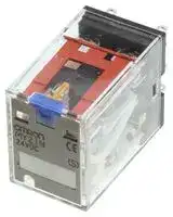


MY2IN DC24 (S)
POWER RELAY, DPDT, 24VDC, 5A, QC
- Manufacturer: OMRON INDUSTRIAL AUTOMATION
- Product type: Power Relays
- Contac; POWER RELAY, DPDT, 24VDC, 5A, QC; Contact Configuration:DPDT; Coil Voltage:24VDC; Contact Current:5A; Product Range:MY Series; Relay Mounting:Socket; Coil Type:Non Latching; Cont
- Coil Type: Non Latching
- Coil Voltage: 24VDC
- Product Range: MY Series
- Relay Mounting: Socket
- Coil Resistance: 636ohm
- Contact Current: 5A
- Relay Terminals: Quick Connect
- Contact Material: Silver
- Contact Voltage VAC: 250V
- Contact Voltage VDC: 30V
- Contact Configuration: DPDT
| Delivery and price | |
|---|---|
| Units per pack | 250 |
| Price | 8.19 € |
| Current stock | 50+ |
| Lead time | 30 days |
**Miniature Power Relays MY**

CSM_MY_DS_J_7_3

# **New Latching Levers for Circuit Checking Added to Our Best-selling MY General-purpose Relays**

- Now lead-free to protect the environment.

- VDE certification (Germany).

- Different colors of coil tape for AC and DC models to more easily distinguish them.

- MY(S) models with latching levers added for easier circuit checking.

**Refer to the** _**Common Relay Precautions**_ **.**

## **Model Number Structure**

|**Structure**<br>**Classification**<br>**Number of**<br>**poles**|**Structure**<br>**Classification**<br>**Number of**<br>**poles**|**Relays with Plug-in Terminals**|**Relays with Plug-in Terminals**|**Relays with Plug-in Terminals**|**PCB terminals**|**Case-surface**<br>**mounting**|
|---|---|---|---|---|---|---|
|||**With operation**<br>**indicator**<br>~~po~~|**Without operation**<br>**indicator**<br>~~po~~|**With latching lever**<br>~~po~~|||
|**Standard models (compliant with**<br>**Electrical Appliances and**<br>**Material Safety Act)**<br>~~==~~|**2**<br>**Bifurcated**<br>~~==~~|**MY2N***<br>**MY2ZN**<br>~~==~~|**MY2***<br>**MY2Z**<br>~~==~~|**MY2IN(S)***|**MY2-02**<br>~~—~~|**MY2F**|
||**3**<br>~~==~~<br>~~ee~~<br>~~Pf~~|**MY3N**<br>~~==~~<br>~~ee~~<br>~~f~~|**MY3**<br>~~==~~<br>~~ee~~<br>~~peee~~|~~ee~~<br>~~e~~|**MY3-02**<br>~~—~~<br>~~ee~~<br>~~ep~~|**MY3F**<br>~~ee~~<br>~~p~~|
||**4**<br>**Bifurcated**<br>~~==~~<br>~~Pf~~|**MY4N***<br>**MY4ZN***<br>~~==~~<br>~~f~~|**MY4***<br>**MY4Z***<br>~~==~~<br>~~peee~~|**MY4IN(S)***<br>**MY4ZIN(S)***<br>~~e~~|**MY4-02**<br>**MY4Z-02**<br>~~—~~<br>~~ep~~|**MY4F**<br>**MY4ZF**<br>~~p~~|
|**Models with diode for coil surge**<br>**absorption (DC coil specification**<br>**only)**<br>~~ie~~<br>a|**2**<br>**Bifurcated**<br>~~Pf~~<br>~~ie~~<br>~~a~~|**MY2N-D2***<br>**MY2ZN-D2**<br>~~f~~<br>~~ie~~<br>~~ee ee~~|**MY2-D***<br>**MY2Z-D**<br>~~peee~~<br>~~ie~~~~**e**~~<br>~~ee~~|**MY2IN-D2(S)***<br>~~e~~<br>~~**e**e~~<br>~~ee~~|---<br>~~ep~~<br>~~e~~<br>~~ee~~|---<br>~~p~~<br>~~e~~|
||**3**<br>~~ie~~<br>~~a~~|**MY3N-D2**<br>~~ie~~<br>~~ee ee~~|**MY3-D**<br>~~ie~~~~**e**~~<br>~~ee~~|~~**e**e~~<br>~~ee~~|||
||**4**<br>**Bifurcated**<br>~~ie~~<br>~~a~~<br>~~e~~|**MY4N-D2***<br>**MY4ZN-D2***<br>~~ie~~<br>~~ee ee~~<br>~~e~~|**MY4-D***<br>**MY4Z-D***<br>~~ie~~~~**e**~~<br>~~ee~~<br>~~e~~|**MY4IN-D2(S)***<br>**MY4ZIN-D2(S)***<br>~~**e**e~~<br>~~ee~~|||
|**Models with CR circuit for coil**<br>**surge absorption (AC coil**<br>**specification only)**<br>~~a~~|**2**|**MY2N-CR***|**MY2-CR***||---<br>~~e~~|~~ee~~|
||**4**<br>**Bifurcated**<br>~~a~~|**MY4N-CR***<br>**MY4ZN-CR***<br>~~a~~|**MY4-CR***<br>**MY4Z-CR***|**MY4IN-CR(S)***<br>**MY4ZIN-CR(S)***<br>~~ee~~|||
|**Models with high contact**<br>**reliability**<br>~~a~~<br>~~a~~|**4  Bifurcated**<br>~~a~~<br>~~a~~|---<br>~~a~~<br>~~ee~~|**MY4Z-CBG**<br>~~ee~~|~~ee~~<br>~~ee~~|~~e~~|~~ee~~|
|**Plastic sealed models**<br>~~a ~~<br>~~a~~<br>~~es~~<br>~~a~~|**4**<br>**Bifurcated**<br> ~~a ~~<br>~~a~~<br>~~ee~~|**MYQ4N**<br> ~~a~~<br>~~ee~~<br>~~ee~~|**MYQ4**<br>**MYQ4Z**<br>~~ee~~<br>~~ee~~|~~ee~~<br>~~ee~~<br>~~ee~~<br>~~ee~~|**MYQ4-02**<br>**MYQ4Z-02**<br>~~e ~~<br>~~ee~~<br>~~ee~~|~~ee~~<br>~~ee~~<br>~~ee~~|
|**Latching models (coil latching)**<br>~~a ~~<br>~~es~~<br>~~a~~|**2**<br> ~~a~~<br>~~ee~~|~~ee~~<br>~~ee~~|**MY2K**<br>~~ee~~<br>~~ee~~|~~ee~~<br>~~ee~~<br>~~ee~~|**MY2K-02**<br>~~ee~~<br>~~ee~~|~~ee~~<br>~~ee~~|
|**Hermetic models**<br>~~es~~<br>~~a~~|**4**<br>**Bifurcated**<br>~~ee~~<br>~~a ~~|~~ee~~<br> ~~a ee~~|**MY4H**<br>**MY4ZH**<br>~~ee~~<br>~~ee~~|~~ee~~<br>~~ee~~<br>~~ee~~|**MY4H-0**<br>**MY4ZH-0**<br>~~ee~~<br>~~ee~~<br>~~ee~~|~~ee~~<br>~~ee~~<br>~~ee~~|


**4.** Products cannot be manufactured for the cells with a diagonal line. Ask your OMRON representative for details on manufacturing products for cells containing “---” in the above table.

Refer to _Connection Socket and Mounting Bracket Selection Table on page 33_ in _Options_ for information on the possible combinations of Models with Plug-in Terminals and Sockets. ~~Po~~

**1** omrRON ~~a~~

**MY**

## **Miniature Power Relays: MY2**

Refer to the standards certifications and compliance section of your OMRON website for the latest information on certified models.

## **Ordering Information**

## **When your order, specify the rated voltage.**

|**Classification**|**Model**|**Rated voltage (V)**|**Rated voltage (V)**|
|---|---|---|---|
|||**Standard products**|**Made-to-order items**|
|Standard models|**MY2**|**12, 24, 100/110, or 200/220 VAC**|110/120 or 220/240 VAC|
|||**12, 24, 48, or 100/110 VDC**||
|Models with built-in operation indicators|**MY2N**|**12, 24, 100/110, 110/120, 200/220, or 220/240 VAC**||
|||**12, 24, 48, or 100/110 VDC**||
|Models with built-in diodes|**MY2-D**|**12, 24, or 100/110 VDC**|48 VDC|
|Models with built-in diodes and operation<br>indicators|**MY2N-D2**|**12, 24, 48, or 100/110 VDC**||
|Models with built-in CR circuits|**MY2-CR**|**100/110 or 200/220 VAC**|110/120 or 220/240 VAC|
|Models with built-in CR circuits and operation<br>indicators|**MY2N-CR**|**100/110 or 200/220 VAC**|110/120 or 220/240 VAC|


- **Note: 1.** Ask your OMRON representative for details on the time required to deliver made-to-order products.

   **2.** Ask your OMRON representative for details on product specifications and the ability to manufacture products with voltages other than the above coil specifications.

   **3.** The above models and specifications are new versions in the MY Series.

   **4.** Except for MY2(N)-CR Relays with the above voltage specifications, all Relays have a height of 53 mm or less. If Mounting Brackets are required, refer to page 33 for selection information.

## **Ratings and Specifications**

## **Ratings**

## **Operating Coils (Standard Models)**

|**Item**|**Item**|**Rated current (mA)**|**Rated current (mA)**|**Coil resistance**<br>**(**Ω**)**|**Coil inductance (H)**|**Coil inductance (H)**|**Must-**<br>**operate**<br>**voltage (V)**|**Must-**<br>**release**<br>**voltage (V)**|**Maximum**<br>**voltage (V)**|**Power consumption**<br>**(VA, W)**|
|---|---|---|---|---|---|---|---|---|---|---|
|**Rated**<br>**voltage (V)**||**50 Hz**|**60 Hz**||**Armature**<br>**OFF**|**Armature**<br>**ON**|||||
|**AC**|**12**|106.5|91|46|0.17|0.33|80% max.*1|30% min.*2|110% of rated<br>voltage|Approx. 1.0 to 1.2<br>(at 60 Hz)|
||**24**|53.8|46|180|0.69|1.3|||||
||**100/110**|11.7/12.9|10/11|3,750|14.54|24.6||||Approx. 0.9 to 1.1<br>(at 60 Hz)|
||**110/120**|9.9/10.8|8.4/9.2|4,430|19.2|32.1|||||
||**200/220**|6.2/6.8|5.3/5.8|12,950|54.75|94.07|||||
||**220/240**|4.8/5.3|4.2/4.6|18,790|83.5|136.4|||||
|**DC**|**12**|72.7||165|0.73|1.37||10% min.*2||Approx. 0.9|
||**24**|36.3||662|3.2|5.72|||||
||**48**|17.6||2,725|10.6|21.0|||||
||**100/110**|8.7/9.6||11,440|45.6|86.2|||||


- **Note: 1.** The rated current and coil resistance are measured at a coil temperature of 23°C with tolerances of +15%/−20% for the AC rated current and ±15% for the DC coil resistance.

   **2.** The AC coil resistance and inductance values are reference values only (at 60 Hz).

   **3.** Operating characteristics were measured at a coil temperature of 23°C.

   **4.** The maximum voltage capacity was measured at an ambient temperature of 23°C.

- *1. There is variation between products, but actual values are 80% max.

To ensure operation, apply at least 80% of the rated value (at a coil temperature of +23° C).

- *2. There is variation between products, but actual values are 30% minimum for AC and 10% minimum for DC. To ensure release, use a value that is lower than the specified value.

## **Contact Ratings**

|**Load**<br>**Item**|**Resistive load**|**Inductive load**<br>**(cos**φ**= 0.4, L/R = 7 ms)**|
|---|---|---|
|**Rated load**|5 A at 220 VAC<br>5 A at 24 VDC|2 A at 220 VAC<br>2 A at 24 VDC|
|**Rated carry current**|5 A||
|**Maximum contact voltage**|250 VAC, 125 VDC||
|**Maximum contact current**|5 A||
|**Contact configuration**|DPDT||
|**Contact structure**|Single||
|**Contact materials**|Ag||


|**Type**<br>**Item**|**Standard**<br>**models**|**Model with built-in operation**<br>**indicator, diode, or CR circuit**|
|---|---|---|
|**Ambient**<br>**operating**<br>**temperature*1**|−55 to 70°C|−55 to 60°C*2|
|**Ambient**<br>**operating**<br>**humidity**|5% to 85%||


- *1. With no icing or condensation.

- *2. This limitation is due to the diode junction temperature and elements used.

**==> picture [539 x 34] intentionally omitted <==**

**2**

**MY**

## **Characteristics**

|**Item**<br>**Type**|**Item**<br>**Type**|**Standard**<br>**models**|**Models with built-**<br>**in operation**<br>**indicators**|**Models with**<br>**built-in CR**<br>**circuits**|**Models with**<br>**built-in**<br>**diodes**|**Model with built-in**<br>**operation indicator**<br>**and diode**|**Model with built-in**<br>**operation indicator**<br>**and CR circuit**|
|---|---|---|---|---|---|---|---|
|**Contact resistance*1**||50 mΩmax.||||||
|**Operation time*2**||20 ms max.||||||
|**Release time*2**||20 ms max.||||||
|**Maximum**<br>**operating**<br>**frequency**|**Mechanical**|18,000 operations/h||||||
||**Rated load**|1,800 operations/h||||||
|**Insulation resistance*3**||100 MΩmin.||||||
|**Dielectric**<br>**strength**|**Between coil and contacts**|2,000 VAC at 50/60 Hz for 1 min.||||||
||**Between contacts of**<br>**different polarity**|||||||
||**Between contacts of the**<br>**same polarity**|1,000 VAC at 50/60 Hz for 1 min.||||||
|**Vibration**<br>**resistance**|**Destruction**|10 to 55 to 10 Hz, 0.5-mm single amplitude (1.0-mm double amplitude)||||||
||**Malfunction**|10 to 55 to 10 Hz, 0.5-mm single amplitude (1.0-mm double amplitude)||||||
|**Shock**<br>**resistance**|**Destruction**|1,000 m/s2||||||
||**Malfunction**|200 m/s2||||||
|**Endurance**|**Mechanical**|AC: 50,000,000 operations min.<br>DC: 100,000,000 operations min.<br>(switching frequency: 18,000 operations/h)||||||
||**Electrical*4**|500,000 operations min.<br>(rated load, switching frequency: 1,800 operations/h)||||||


- *4. Ambient temperature condition: 23°C

- *5. This value was measured at a switching frequency of 120 operations per minute.

## **Dimensions**

**(Unit: mm)**

**MY2, MY2N, MY2-D, MY2N-D2, MY2-CR, and MY2N-CR**

**==> picture [474 x 132] intentionally omitted <==**

**----- Start of picture text -----**<br>
Terminal Arrangement/In- MY2N<br>ternal Connections  PO<br>DC Models AC Models<br>(Bottom View)<br>Standard Models<br>oo<br>2.6<br>Eight, 1.2-dia. × 2.2 oval holes<br>wy) [c][E] 0.5 [1a]fa yeas?ig al! 5 3 |!<br>28 max.<br>(The coil has no polarity.)<br>3 6 max . 6.4 Check the coil polarity when wiring  (The coil has no polarity.)<br>21.5 max. and wire all connections correctly.<br>**----- End of picture text -----**<br>


- **Note: 1.** An AC model has coil disconnection selfdiagnosis.

   **2.** For the DC models, check the coil polarity when wiring and wire all connections correctly.

   **3.** The indicator is red for AC and green for DC.

   **4.** The operation indicator indicates the energization of the coil and does not represent contact operation.

**==> picture [151 x 116] intentionally omitted <==**

**----- Start of picture text -----**<br>
MY2-D MY2N-D2<br>Check the coil polarity when wiring<br>and wire all connections correctly. ) Check the coil polarity when wiring<br>and wire all connections correctly.<br>**----- End of picture text -----**<br>


**==> picture [127 x 6] intentionally omitted <==**

**----- Start of picture text -----**<br>
MY2-CR MY2N-CR<br>**----- End of picture text -----**<br>


**==> picture [57 x 6] intentionally omitted <==**

**----- Start of picture text -----**<br>
(The coil has no polarity.)<br>**----- End of picture text -----**<br>


**==> picture [57 x 6] intentionally omitted <==**

**----- Start of picture text -----**<br>
(The coil has no polarity.)<br>**----- End of picture text -----**<br>


**3** omRON ~~a~~

**MY**

## **Miniature Power Relays: MY2Z**

Refer to the standards certifications and compliance section of your OMRON website for the latest information on certified models.

## **Ordering Information**

**When your order, specify the rated voltage.**

|**Classification**|**Model**|**Rated voltage (V)**|**Rated voltage (V)**|
|---|---|---|---|
|||**Standard products**|**Made-to-order items**|
|Standard models|**MY2Z**|**100/110 or 200/220 VAC**|12, 24, 100/120, or 200/240 VAC|
|||**12 or 24 VDC**|48 or 100/110 VDC|
|Models with built-in operation indicators|**MY2ZN**|**100/110 or 200/220 VAC**|12, 24, 100/120, or 200/240 VAC|
|||**24 VDC**|12, 48, or 100/110 VDC|
|Models with built-in diodes|**MY2Z-D**|**24 VDC**|12 or 100/110 VDC|
|Models with built-in diodes and operation<br>indicators|**MY2ZN-D2**|**24 or 100/110 VDC**|12 VDC|
|Models with built-in CR circuits|**MY2Z-CR**||100/110 or 200/220 VAC|
|Models with built-in CR circuits and operation<br>indicators|**MY2ZN-CR**|**100/110 VAC**|200/220 VAC|


- **Note: 1.** Ask your OMRON representative for details on the time required to deliver made-to-order products.

   **2.** Ask your OMRON representative for details on product specifications and the ability to manufacture products with voltages other than the above coil specifications.

## **Ratings and Specifications**

## **Ratings**

## **Operating Coil (Standard Models)**

|**Item**|**Item**|**Rated current (mA)**|**Rated current (mA)**|**Coil resistance**<br>**(**Ω**)**|**Coil inductance (H)**|**Coil inductance (H)**|**Must-**<br>**operate**<br>**voltage (V)**|**Must-**<br>**release**<br>**voltage (V)**|**Maximum**<br>**voltage (V)**|**Power consumption**<br>**(VA, W)**|
|---|---|---|---|---|---|---|---|---|---|---|
|**Rated**<br>**voltage (V)**||**50 Hz**|**60 Hz**||**Armature**<br>**OFF**|**Armature**<br>**ON**|||||
|**AC**|**12**|106.5|91|46|0.17|0.33|80% max.*1|30% min.*2|110% of rated<br>voltage|Approx. 1.0 to 1.2<br>(at 60 Hz)|
||**24**|53.8|46|180|0.69|1.3|||||
||**100/110**|11.7/12.9|10/11|3,750|14.54|24.6||||Approx. 0.9 to 1.1<br>(at 60 Hz)|
||**110/120**|9.9/10.8|8.4/9.2|4,430|19.2|32.1|||||
||**200/220**|6.2/6.8|5.3/5.8|12,950|54.75|94.07|||||
||**220/240**|4.8/5.3|4.2/4.6|18,790|83.5|136.4|||||
|**DC**|**12**|75||160|0.73|1.37||10% min.*2||Approx. 0.9|
||**24**|36.9||650|3.2|5.72|||||
||**48**|18.5||2,600|10.6|21.0|||||
||**100/110**|9.1/10||11,000|45.6|86.2|||||


- **Note: 1.** The rated current and coil resistance are measured at a coil temperature of 23°C with tolerances of +15%/−20% for the AC rated current and ±15% for the DC coil resistance.

   **2.** The AC coil resistance and inductance values are reference values only (at 60 Hz).

   **3.** Operating characteristics were measured at a coil temperature of 23°C.

   **4.** The maximum voltage capacity was measured at an ambient temperature of 23°C.

- *1. There is variation between products, but actual values are 80% max.

   - To ensure operation, apply at least 80% of the rated value

- *2. There is variation between products, but actual values are 30% minimum for AC and 10% minimum for DC. To ensure release, use a value that is lower than the specified value.

## **Contact Ratings**

|**Load**<br>**Item**|**Resistive load**|**Inductive load**<br>**(cos**φ**= 0.4, L/R = 7 ms)**|
|---|---|---|
|**Rated load**|5 A at 220 VAC<br>5 A at 24 VDC|2 A at 220 VAC<br>2 A at 24 VDC|
|**Rated carry current**|5 A||
|**Maximum contact voltage**|250 VAC, 125 VDC||
|**Maximum contact current**|5 A||
|**Contact configuration**|DPDT||
|**Contact structure**|Bifurcated||
|**Contact materials**|Au plating + Ag||


|**Type**<br>**Item**|**Standard**<br>**models**|**Model with built-in operation**<br>**indicator, diode, or CR circuit**|
|---|---|---|
|**Ambient**<br>**operating**<br>**temperature*1**|−55 to 70° C|−55 to 60° C*2|
|**Ambient**<br>**operating**<br>**humidity**|5% to 85%||


- *1. With no icing or condensation.

- *2. This limitation is due to the diode junction temperature and elements used.

**==> picture [539 x 34] intentionally omitted <==**

**4**

**MY**

## **Characteristics**

|**Item**<br>**Type**|**Item**<br>**Type**|**Standard**<br>**models**|**Models with built-**<br>**in operation**<br>**indicators**|**Models with**<br>**built-in**<br>**diodes**|**Model with built-in**<br>**operation indicator**<br>**and diode**|**Models with**<br>**built-in CR**<br>**circuits**|**Models with built-in**<br>**CR circuits and**<br>**operation indicators**|
|---|---|---|---|---|---|---|---|
|**Contact resistance*1**<br>50 m||50 mΩmax.||||||
|**Operation time*2**<br>20 ms max.||20 ms max.||||||
|**Release time*2**<br>20 ms max.||20 ms max.||||||
|**Maximum**<br>**operating**<br>**frequency**|**Mechanical**<br>18,000 operations/h|18,000 operations/h||||||
||**Rated load**<br>1,800 operations/h|1,800 operations/h||||||
|**Insulation resistance*3**<br>100 M||100 MΩmin.||||||
|**Dielectric**<br>**strength**|**Between coil and contacts**<br>2,000 VAC at 50/60 Hz for 1 min.<br>**Between contacts of**<br>**different polarity**|2,000 VAC at 50/60 Hz for 1 min.||||||
||**Between contacts of the**<br>**same polarity**<br>1,000 VAC at 50/60 Hz for 1 min.|1,000 VAC at 50/60 Hz for 1 min.||||||
|**Vibration**<br>**resistance**|**Destruction**<br>10 to 55 to 10 Hz, 0.5-mm single amplitude (1.0-mm double amplitude)|10 to 55 to 10 Hz, 0.5-mm single amplitude (1.0-mm double amplitude)||||||
||**Malfunction**<br>10 to 55 to 10 Hz, 0.5-mm single amplitude (1.0-mm double amplitude)|10 to 55 to 10 Hz, 0.5-mm single amplitude (1.0-mm double amplitude)||||||
|**Shock**<br>**resistance**|**Destruction**<br>1,000 m/s|1,000 m/s2||||||
||**Malfunction**<br>200 m/s|200 m/s2||||||
|**Endurance**|**Mechanical**<br>50,000,000 operations min. (operating frequency: 18,000 operations/h)|50,000,000 operations min. (operating frequency: 18,000 operations/h)||||||
||**Electrical*4**<br>200,000 operations min. (rated load, switching frequency: 1,800 operations/h)|200,000 operations min. (rated load, switching frequency: 1,800 operations/h)||||||


- *4. Ambient temperature condition: 23°C

- *5. This value was measured at a switching frequency of 120 operations per minute.

## **Dimensions**

**(Unit: mm)**

**MY2Z, MY2ZN, MY2Z-D, MY2ZN-D2, MY2Z-CR, and MY2ZN-CR**

**==> picture [465 x 148] intentionally omitted <==**

**----- Start of picture text -----**<br>
Terminal Arrangement/ MY2ZN<br>Internal Connections<br>DC Models AC Models<br>(Bottom View)<br>Standard Models<br>2.6 f. a) ——— / ai s 2]<br>Eight, 1.2-dia. × 2.2 oval holes<br>g b 0.5 a ipaiies<br>28 max.<br>gen K * 9 (The coil has no polarity.) ~<br>3 6 max . 6.4 Check the coil polarity when wiring  (The coil has no polarity.)<br>21.5 max. and wire all connections correctly.<br>* For the MY2Z-CR and MY2ZN-CR,  Note: 1. An AC model has coil disconnection self-<br>this dimension is 53 mm max.<br>**----- End of picture text -----**<br>


- **Note: 1.** An AC model has coil disconnection selfdiagnosis.

   **2.** For the DC models, check the coil polarity when wiring and wire all connections correctly.

   **3.** The indicator is red for AC and green for DC.

   **4.** The operation indicator indicates the energization of the coil and does not represent contact operation.

**==> picture [131 x 62] intentionally omitted <==**

**----- Start of picture text -----**<br>
MY2Z-CR MY2ZN-CR<br>1 4<br>5 8<br>9 12<br>13 14<br>**----- End of picture text -----**<br>


**==> picture [351 x 117] intentionally omitted <==**

**----- Start of picture text -----**<br>
MY2Z-D MY2ZN-D2 MY2Z-CR MY2ZN-CR<br>1 4<br>5 8<br>9 12<br>13 14<br>Check the coil polarity when wiring<br>and wire all connections correctly. Check the coil polarity when wiring  (The coil has no polarity.) (The coil has no polarity.)<br>) () and wire all connections correctly.<br>**----- End of picture text -----**<br>


**5** omrRONn ~~a~~

**MY**

## **Miniature Power Relays: MY3**

Refer to the standards certifications and compliance section of your OMRON website for the latest information on certified models.

## **Ordering Information**

**When your order, specify the rated voltage.**

|**Classification**|**Model**|**Rated voltage (V)**|**Rated voltage (V)**|
|---|---|---|---|
|||**Standard products**|**Made-to-order items**|
|Standard models|**MY3**|**24, 100/110, 200/220, or 220/240 VAC**|12, or 110/120 VAC|
|||**12, 24, or 100/110 VDC**|48 VDC|
|Models with built-in operation indicators|**MY3N**|**24, 100/110, 200/220, or 220/240 VAC**|12, or 110/120 VAC|
|||**24 VDC**|12, 48, or 100/110 VDC|
|Models with built-in diodes|**MY3-D**|**24 VDC**|12 or 100/110 VDC|
|Models with built-in diodes and operation<br>indicators|**MY3N-D2**|**24 VDC**|12 or 100/110 VDC|


- **Note: 1.** Ask your OMRON representative for details on the time required to deliver made-to-order products.

   **2.** Ask your OMRON representative for details on product specifications and the ability to manufacture products with voltages other than the above coil specifications.

## **Ratings and Specifications**

## **Ratings**

## **Operating Coil (Standard Models)**

|**Item**|**Item**|**Rated current (mA)**|**Rated current (mA)**|**Coil resistance**<br>**(**Ω**)**|**Coil inductance (H)**|**Coil inductance (H)**|**Must-**<br>**operate**<br>**voltage (V)**|**Must-**<br>**release**<br>**voltage (V)**|**Maximum**<br>**voltage (V)**|**Power consumption**<br>**(VA, W)**|
|---|---|---|---|---|---|---|---|---|---|---|
|**Rated**<br>**voltage (V)**||**50 Hz**|**60 Hz**||**Armature**<br>**OFF**|**Armature**<br>**ON**|||||
|**AC**|**12**|106.5|91|46|0.17|0.33|80% max.*1|30% min.*2|110% of rated<br>voltage|Approx. 1.0 to 1.2<br>(at 60 Hz)|
||**24**|53.8|46|180|0.69|1.3|||||
||**100/110**|11.7/12.9|10/11|3,750|14.54|24.6||||Approx. 0.9 to 1.1<br>(at 60 Hz)|
||**110/120**|9.9/10.8|8.4/9.2|4,430|19.2|32.1|||||
||**200/220**|6.2/6.8|5.3/5.8|12,950|54.75|94.07|||||
||**220/240**|4.8/5.3|4.2/4.6|18,790|83.5|136.4|||||
|**DC**|**12**|75||160|0.73|1.37||10% min.*2||Approx. 0.9|
||**24**|36.9||650|?3.2|5.72|||||
||**48**|18.5||2,600|10.6|21.0|||||
||**100/110**|9.1/10||11,000|45.6|86.2|||||


- **Note: 1.** The rated current and coil resistance are measured at a coil temperature of 23°C with tolerances of +15%/−20% for the AC rated current and ±15% for the DC coil resistance.

   **2.** The AC coil resistance and inductance values are reference values only (at 60 Hz).

   **3.** Operating characteristics were measured at a coil temperature of 23°C.

   **4.** The maximum voltage capacity was measured at an ambient temperature of 23°C.

- *1. There is variation between products, but actual values are 80% max.

   - To ensure operation, apply at least 80% of the rated value

- *2. There is variation between products, but actual values are 30% minimum for AC and 10% minimum for DC. To ensure release, use a value that is lower than the specified value.

## **Contact Ratings**

|**Load**<br>**Item**|**Resistive load**|**Inductive load**<br>**(cos**φ**= 0.4, L/R = 7 ms)**|
|---|---|---|
|**Rated load**|5 A at 220 VAC<br>5 A at 24 VDC|2 A at 220 VAC<br>2 A at 24 VDC|
|**Rated carry current**|5 A||
|**Maximum contact voltage**|250 VAC, 125 VDC||
|**Maximum contact current**|5 A||
|**Contact configuration**|3PDT||
|**Contact structure**|Single||
|**Contact materials**|Ag||


|**Type**<br>**Item**|**Standard**<br>**models**|**Operation indicator and diode**|
|---|---|---|
|**Ambient**<br>**operating**<br>**temperature*1**|−55 to 70° C|−55 to 60° C*2|
|**Ambient**<br>**operating**<br>**humidity**|5% to 85%||


- *1. With no icing or condensation.

- *2. This limitation is due to the diode junction temperature and elements used.

**==> picture [539 x 34] intentionally omitted <==**

**6**

**MY**

## **Characteristics**

|**Item**<br>**Type**|**Item**<br>**Type**|**Item**<br>**Type**|**Standard models**|**Models with built-in**<br>**operation indicators**|**Models with built-in**<br>**diodes**|**Model with built-in operation**<br>**indicator and diode**|
|---|---|---|---|---|---|---|
|**Contact resistance*1**<br>|||50 mΩmax.||||
|**Operation time*2**<br>|||20 ms max.||||
|**Release time*2**<br>|||20 ms max.||||
|**Maximum**<br>**operating**<br>**frequency**|**Mechanical**<br>||18,000 operations/h||||
||**Rated load**<br>||1,800 operations/h||||
|**Insulation resistance*3**<br>|||100 MΩmin.||||
|**Dielectric**<br>**strength**|**Between coil and contacts**<br> <br>**Between contacts of**<br>**different polarity**||2,000 VAC at 50/60 Hz for 1 min.||||
||**Between contacts of the**<br>**same polarity**<br>||1,000 VAC at 50/60 Hz for 1 min.||||
|**Vibration**<br>**resistance**|**Destruction**<br>||10 to 55 to 10 Hz, 0.5-mm single amplitude (1.0-mm double amplitude)||||
||**Malfunction**<br>||10 to 55 to 10 Hz, 0.5-mm single amplitude (1.0-mm double amplitude)||||
|**Shock**<br>**resistance**|**Destruction**<br>||1,000 m/s2||||
||**Malfunction**<br>||200 m/s2||||
|**Endurance**|**Mechanical**<br> <br> <br>(||AC: 50,000,000 operations min.<br>DC: 100,000,000 operations min.<br>switching frequency: 18,000 operations/h)||||
||**Electrical*4**<br>||500,000 operations min. (rated load, switching frequency: 1,800 operations/h)||||
||||||||
|**Item      Number of poles**||**3 poles**<br><br>|||||
|**Failure rate P value**<br>**(reference value)*5**||1 mA at 5 VDC<br><br>|||||
|**Weight**||Approx. 35 g|||||


- *5. This value was measured at a switching frequency of 120 operations per minute.

## **Dimensions**

## **(Unit: mm)**

## **MY3, MY3N, MY3-D, and MY3N-D2**

**==> picture [405 x 140] intentionally omitted <==**

**----- Start of picture text -----**<br>
Terminal Arrangement/ MY3N<br>Internal Connections<br>DC Models AC Models<br>(Bottom View)<br>Standard Models<br>2.6<br>Eleven, 1.2-dia. × 2.2 oval holes<br>0.5<br>28 max.<br>6.3 (The coil has no polarity.)<br>0.5<br>3 6 max . 6.4 21.5 max. Check the coil polarity when wiring  (The coil has no polarity.)<br>and wire all connections correctly.<br>**----- End of picture text -----**<br>


**==> picture [55 x 78] intentionally omitted <==**

- **Note: 1.** An AC model has coil disconnection selfdiagnosis.

   **2.** For the DC models, check the coil polarity when wiring and wire all connections correctly.

   **3.** The indicator is red for AC and green for DC.

   **4.** The operation indicator indicates the energization of the coil and does not represent contact operation.

**==> picture [161 x 136] intentionally omitted <==**

**----- Start of picture text -----**<br>
MY3-D MY3N-D2<br>Check the coil polarity when wiring  Check the coil polarity when wiring<br>and wire all connections correctly. and wire all connections correctly.<br>**----- End of picture text -----**<br>


**==> picture [539 x 34] intentionally omitted <==**

**7**

**MY**

## **Miniature Power Relays: MY4**

Refer to the standards certifications and compliance section of your OMRON website for the latest information on certified models.

## **Ordering Information**

**When your order, specify the rated voltage.**

|**Classification**|**Model**|**Rated voltage (V)**|**Rated voltage (V)**|
|---|---|---|---|
|||**Standard products**|**Made-to-order items**|
|Standard models|**MY4**|**24, 100/110, or 200/220 VAC**|12, 110/120, or 220/240 VAC|
|||**12, 24, 48, or 100/110 VDC**||
|Models with built-in operation indicators|**MY4N**|**12, 24, 100/110, 110/120, 200/220, or 220/240 VAC**||
|||**12, 24, 48, or 100/110 VDC**||
|Models with built-in diodes|**MY4-D**|**12, 24, 48, or 100/110 VDC**||
|Models with built-in diodes and operation<br>indicators|**MY4N-D2**|**12, 24, or 100/110 VDC**|48 VDC|
|Models with built-in CR circuits|**MY4-CR**|**100/110 or 200/220 VAC**|110/120 or 220/240 VAC|
|Models with built-in CR circuits and operation<br>indicators|**MY4N-CR**|**100/110, 110/120, or 200/220 VAC**|220/240 VAC|


- **Note: 1.** Ask your OMRON representative for details on the time required to deliver made-to-order products.

   **2.** Ask your OMRON representative for details on product specifications and the ability to manufacture products with voltages other than the above coil specifications.

   **3.** The above models and specifications are new versions in the MY Series.

   **4.** Except for MY4(N)-CR Relays with the above voltage specifications, all Relays have a height of 53 mm or less. If Mounting Brackets are required, refer to page 33 for selection information.

## **Ratings and Specifications**

## **Ratings**

## **Operating Coil (Standard Models)**

|**Item**|**Item**|**Rated current (mA)**|**Rated current (mA)**|**Coil resistance**<br>**(**Ω**)**|**Coil inductance (H)**|**Coil inductance (H)**|**Must-**<br>**operate**<br>**voltage (V)**|**Must-**<br>**release**<br>**voltage (V)**|**Maximum**<br>**voltage (V)**|**Power consumption**<br>**(VA, W)**|
|---|---|---|---|---|---|---|---|---|---|---|
|**Rated**<br>**voltage (V)**||**50 Hz**|**60 Hz**||**Armature**<br>**OFF**|**Armature**<br>**ON**|||||
|**AC**|**12**|106.5|91|46|0.17|0.33|80% max.*1|30% min.*2|110% of rated<br>voltage|Approx. 1.0 to 1.2<br>(at 60 Hz)|
||**24**|53.8|46|180|0.69|1.3|||||
||**100/110**|11.7/12.9|10/11|3,750|14.54|24.6||||Approx. 0.9 to 1.1<br>(at 60 Hz)|
||**110/120**|9.9/10.8|8.4/9.2|4,430|19.2|32.1|||||
||**200/220**|6.2/6.8|5.3/5.8|12,950|54.75|94.07|||||
||**220/240**|4.8/5.3|4.2/4.6|18,790|83.5|136.4|||||
|**DC**|**12**|72.7||165|0.73|1.37||10% min.*2||Approx. 0.9|
||**24**|36.3||662|3.2|5.72|||||
||**48**|17.6||2,725|10.6|21.0|||||
||**100/110**|8.7/9.6||11,440|45.6|86.2|||||


- **Note: 1.** The rated current and coil resistance are measured at a coil temperature of 23°C with tolerances of +15%/−20% for the AC rated current and ±15% for the DC coil resistance.

   **2.** The AC coil resistance and inductance values are reference values only (at 60 Hz).

   **3.** Operating characteristics were measured at a coil temperature of 23°C.

   **4.** The maximum voltage capacity was measured at an ambient temperature of 23°C.

- *1. There is variation between products, but actual values are 80% max.

   - To ensure operation, apply at least 80% of the rated value

- *2. There is variation between products, but actual values are 30% minimum for AC and 10% minimum for DC. To ensure release, use a value that is lower than the specified value.

## **Contact Ratings**

|**Load**<br>**Item**|**Resistive load**|**Inductive load**<br>**(cos**φ**= 0.4, L/R = 7 ms)**|
|---|---|---|
|**Rated load**|3 A at 220 VAC<br>3 A at 24 VDC|0.8 A at 220 VAC<br>1.5 A at 24 VDC|
|**Rated carry current**|3 A||
|**Maximum contact voltage**|250 VAC, 125 VDC||
|**Maximum contact current**|3 A||
|**Contact configuration**|4PDT||
|**Contact structure**|Single||
|**Contact materials**|Au cladding + Ag alloy||


|**Type**<br>**Item**|**Standard**<br>**models**|**Model with built-in operation**<br>**indicator, diode, or CR circuit**|
|---|---|---|
|**Ambient**<br>**operating**<br>**temperature*1**|−55 to 70° C|−55 to 60° C*2|
|**Ambient**<br>**operating**<br>**humidity**|5% to 85%||


- *1. With no icing or condensation.

- *2. This limitation is due to the diode junction temperature and elements used.

**==> picture [539 x 34] intentionally omitted <==**

**8**

**MY**

## **Characteristics**

|**Item**<br>**Type**|**Item**<br>**Type**|**Item**<br>**Type**|**Standard**<br>**models**|**Models with built-**<br>**in operation**<br>**indicators**|**Models with**<br>**built-in CR**<br>**circuits**|**Models with**<br>**built-in**<br>**diodes**|**Model with built-in**<br>**operation indicator**<br>**and diode**|**Model with built-in**<br>**operation indicator**<br>**and CR circuit**|
|---|---|---|---|---|---|---|---|---|
|**Contact resistance*1**|||50 mΩmax.||||||
|**Operation time*2**|||20 ms max.||||||
|**Release time*2**|||20 ms max.||||||
|**Maximum**<br>**operating**<br>**frequency**|**Mechanical**||18,000 operations/h||||||
||**Rated load**||1,800 operations/h||||||
|**Insulation resistance*3**|||100 MΩmin.||||||
|**Dielectric**<br>**strength**|**Between coil and contacts**||2,000 VAC at 50/60 Hz for 1 min.||||||
||**Between contacts of**<br>**different polarity**||||||||
||**Between contacts of the**<br>**same polarity**||1,000 VAC at 50/60 Hz for 1 min.||||||
|**Vibration**<br>**resistance**|**Destruction**||10 to 55 to 10 Hz, 0.5-mm single amplitude (1.0-mm double amplitude)||||||
||**Malfunction**||10 to 55 to 10 Hz, 0.5-mm single amplitude (1.0-mm double amplitude)||||||
|**Shock**<br>**resistance**|**Destruction**||1,000 m/s2||||||
||**Malfunction**||200 m/s2||||||
|**Endurance**|**Mechanical**||AC: 50,000,000 operations min.<br>DC: 100,000,000 operations min.<br>(switching frequency:: 18,000 operations/h)||||||
||**Electrical*4**||200,000 operations min.<br>(rated load, switching frequency: 1,800 operations/h)||||||
||||||||||
|**ItemNumber of poles**||**4 poles**|||||||
|**Failure rate P value**<br>**(reference value)*5**||1 mA at 1 VDC|||||||
|**Weight**||Approx. 35 g|||||||


- *5. This value was measured at a switching frequency of 120 operations per minute.

## **Engineering Data**

## **List of Actual Load Endurance** (Refer to _Engineering Data on page 20_ .)

|**Model**|**Load type**|**Conditions**|**Switching frequency**|**Electrical durability**<br>**(operations min.)**|
|---|---|---|---|---|
|**MY4 DC24V**|AC magnetic switch|35 VA at 100 VAC<br>Making current: 4 A,<br>Steady-state current: 0.35 A|ON: 1s<br>OFF: 3s|500,000|
||DC solenoid|40 W at 24 VDC<br>Steady-state current:<br>1.6 A, L/R = 10 ms<br>Surge-absorbing diode connected|ON: 0.5s<br>OFF: 1.5s|500,000|
|||20 W at 24 VDC<br>Steady-state current:<br>0.8 A, L/R = 10 ms<br>Surge-absorbing diode connected|ON: 0.5s<br>OFF: 1.5s|1,000,000|


**==> picture [539 x 34] intentionally omitted <==**

**9**

**MY**

**Dimensions**

**(Unit: mm)**

**MY4, MY4N, MY4-D, MY4N-D2, MY4-CR, and MY4N-CR**

**==> picture [386 x 154] intentionally omitted <==**

**----- Start of picture text -----**<br>
PO MY4N<br>Terminal Arrangement/ ee DC Models AC Models<br>Internal Connections<br>(Bottom View)<br>Standard Models<br>2.6<br>Fourteen, 1.2-dia. × 2.2 oval holes<br>0.5<br>28 max.<br>Check the coil polarity when wiring  (The coil has no polarity.)<br>and wire all connections correctly.<br>(The coil has no polarity.)<br>3 6 max . 6.4 Pt 21.5 max. Note: 1. An AC model has coil disconnection self- )<br>diagnosis.<br>**----- End of picture text -----**<br>


**==> picture [81 x 25] intentionally omitted <==**

**----- Start of picture text -----**<br>
i e<br>**----- End of picture text -----**<br>


**2.** For the DC models, check the coil polarity when wiring and wire all connections correctly.

**3.** The indicator is red for AC and green for DC.

**==> picture [362 x 141] intentionally omitted <==**

**----- Start of picture text -----**<br>
4. The operation indicator indicates the<br>energization of the coil and does not represent<br>contact operation.<br>MY4-D MY4N-D2 MY4-CR MY4N-CR<br>ye<br>Check the coil polarity when wiring and wire all connections correctly. Check the coil polarity when wiring and wire all connections correctly. (The coil has no polarity.) (The coil has no polarity.)<br>**----- End of picture text -----**<br>


**10** omRON ~~a~~

**MY**

## **Miniature Power Relays: MY4Z**

Refer to the standards certifications and compliance section of your OMRON website for the latest information on certified models.

## **Ordering Information**

**When your order, specify the rated voltage.**

|**Classification**|**Model**|**Rated voltage (V)**|**Rated voltage (V)**|
|---|---|---|---|
|||**Standard products**|**Made-to-order items**|
|Standard models|**MY4Z**|**100/110 or 200/220 VAC**|110/120 or 220/240 VAC|
|||**12, 24, 48, or 100/110 VDC**||
|Models with built-in operation indicators|**MY4ZN**|**100/110 or 200/220 VAC**|24, 110/120, or 220/240 VAC|
|||**24 or 100/110 VDC**|12 or 48 VDC|
|Models with built-in diodes|**MY4Z-D**|**24 or 100/110 VDC**|12 or 48 VDC|
|Models with built-in diodes and operation<br>indicators|**MY4ZN-D2**|**12, 24, 48, or 100/110 VDC**||
|Models with built-in CR circuits|**MY4Z-CR**|**100/110 or 200/220 VAC**|110/120 or 220/240 VAC|
|Models with built-in CR circuits and operation<br>indicators|**MY4ZN-CR**|**100/110 or 200/220 VAC**|110/120 or 220/240 VAC|


- **Note: 1.** Ask your OMRON representative for details on the time required to deliver made-to-order products.

   **2.** Ask your OMRON representative for details on product specifications and the ability to manufacture products with voltages other than the above coil specifications.

   **3.** The above models and specifications are new versions in the MY Series.

## **Ratings and Specifications**

## **Ratings**

## **Operating Coil (Standard Models)**

|**Item**|**Item**|**Rated current (mA)**|**Rated current (mA)**|**Coil resistance**<br>**(**Ω**)**|**Coil inductance (H)**|**Coil inductance (H)**|**Must-**<br>**operate**<br>**voltage (V)**|**Release**<br>**voltage (V)**|**Maximum**<br>**voltage (V)**|**Power consumption**<br>**(VA, W)**|
|---|---|---|---|---|---|---|---|---|---|---|
|**Rated**<br>**voltage (V)**||**50 Hz**|**60 Hz**||**Armature**<br>**OFF**|**Armature**<br>**ON**|||||
|AC|12|106.5|91|46|0.17|0.33|80% max.*1|30% min.*2|110% of rated<br>voltage|Approx. 1.0 to 1.2<br>(at 60 Hz)|
||24|53.8|46|180|0.69|1.3|||||
||100/110|11.7/12.9|10/11|3,750|14.54|24.6||||Approx. 0.9 to 1.1<br>(at 60 Hz)|
||110/120|9.9/10.8|8.4/9.2|4,430|19.2|32.1|||||
||200/220|6.2/6.8|5.3/5.8|12,950|54.75|94.07|||||
||220/240|4.8/5.3|4.2/4.6|18,790|83.5|136.4|||||
|DC|12|72.7||165|0.73|1.37||10% min.*2||Approx. 0.9|
||24|36.3||662|3.2|5.72|||||
||48|17.6||2,725|10.6|21.0|||||
||100/110|8.7/9.6||11,440|45.6|86.2|||||


- **Note: 1.** The rated current and coil resistance are measured at a coil temperature of 23°C with tolerances of +15%/−20% for the AC rated current and ±15% for the DC coil resistance.

   **2.** The AC coil resistance and inductance values are reference values only (at 60 Hz).

   **3.** Operating characteristics were measured at a coil temperature of 23°C.

   **4.** The maximum voltage capacity was measured at an ambient temperature of 23°C.

- *1. There is variation between products, but actual values are 80% max.

   - To ensure operation, apply at least 80% of the rated value

- *2. There is variation between products, but actual values are 30% minimum for AC and 10% minimum for DC. To ensure release, use a value that is lower than the specified value.

## **Contact Ratings**

|**Load**<br>**Item**|**Resistive load**|**Inductive load**<br>**(cos**φ**= 0.4, L/R = 7 ms)**|
|---|---|---|
|**Rated load**|3 A at 220 VAC<br>3 A at 24 VDC|0.8 A at 220 VAC<br>1.5 A at 24 VDC|
|**Rated carry current**|3 A||
|**Maximum contact voltage**|250 VAC, 125 VDC||
|**Maximum contact current**|3 A||
|**Contact configuration**|4PDT||
|**Contact structure**|Bifurcated||
|**Contact materials**|Au cladding + Ag alloy||


|**Type**<br>**Item**|**Standard**<br>**models**|**Model with built-in operation**<br>**indicator, diode, or CR circuit**|
|---|---|---|
|**Ambient**<br>**operating**<br>**temperature*1**|−55 to 70° C|−55 to 60° C|
|**Ambient**<br>**operating**<br>**humidity**|5% to 85%||


- *1. With no icing or condensation.

- *2. This limitation is due to the diode junction temperature and elements used.

**==> picture [539 x 34] intentionally omitted <==**

**11**

**MY**

## **Characteristics**

|**Item**<br>**Type**<br>**Standard**<br>**models**|**Item**<br>**Type**<br>**Standard**<br>**models**|**Standard**<br>**models**|**Models with built-**<br>**in operation**<br>**indicators**|**Models with**<br>**built-in CR**<br>**circuits**|**Models with**<br>**built-in**<br>**diodes**|**Model with built-in**<br>**operation indicator**<br>**and diode**|**Model with built-in**<br>**operation indicator**<br>**and CR circuit**|
|---|---|---|---|---|---|---|---|
|**Contact resistance*1**<br>50 m||50 mΩmax.||||||
|**Operation time*2**<br>20 ms max.||20 ms max.||||||
|**Release time*2**<br>20 ms max.||20 ms max.||||||
|**Maximum**<br>**operating**<br>**frequency**|**Mechanical**<br>18,000 operations/h|18,000 operations/h||||||
||**Rated load**<br>1,800 operations/h|1,800 operations/h||||||
|**Insulation resistance*3**<br>100 M||100 MΩmin.||||||
|**Dielectric**<br>**strength**|**Between coil and contacts**<br>2,000 VAC at 50/60 Hz for 1 min.<br>**Between contacts of**<br>**different polarity**|2,000 VAC at 50/60 Hz for 1 min.||||||
||**Between contacts of the**<br>**same polarity**<br>1,000 VAC at 50/60 Hz for 1 min.|1,000 VAC at 50/60 Hz for 1 min.||||||
|**Vibration**<br>**resistance**|**Destruction**<br>10 to 55 to 10 Hz, 0.5-mm single amplitude (1.0-mm double amplitude)|10 to 55 to 10 Hz, 0.5-mm single amplitude (1.0-mm double amplitude)||||||
||**Malfunction**<br>10 to 55 to 10 Hz, 0.5-mm single amplitude (1.0-mm double amplitude)|10 to 55 to 10 Hz, 0.5-mm single amplitude (1.0-mm double amplitude)||||||
|**Shock**<br>**resistance**|**Destruction**<br>1,000 m/s|1,000 m/s2||||||
||**Malfunction**<br>200 m/s|200 m/s2||||||
|**Endurance**|**Mechanical**<br>20,000,000 operations min.<br>(switching frequency: 18,000 operations/h)|20,000,000 operations min.<br>(switching frequency: 18,000 operations/h)||||||
||**Electrical*4**<br>100,000 operations min.<br>(rated load, switching frequency: 1,800 operations/h)|100,000 operations min.<br>(rated load, switching frequency: 1,800 operations/h)||||||


- *4. Ambient temperature condition: 23° C

- *5. This value was measured at a switching frequency of 120 operations per minute.

## **Dimensions**

**(Unit: mm)**

**MY4Z, MY4ZN, MY4Z-D, MY4ZN-D2, MY4Z-CR, and MY4ZN-CR**

**==> picture [388 x 152] intentionally omitted <==**

**----- Start of picture text -----**<br>
MY4ZN<br>DC Models AC Models<br>ee ee<br>Terminal Arrangement/<br>Internal Connections<br>(Bottom View)<br>Standard Models -|=|4|- a a<br>2.6<br>Fourteen, 1.2-dia. × 2.2 oval holes<br>0.5<br>28 max.<br>Check the coil polarity when wiring  (The coil has no polarity.)<br>and wire all connections correctly.<br>(The coil has no polarity.)<br>3 6 max . 6.4 Note: 1. An AC model has coil disconnection self-<br>21.5 max. diagnosis.<br>**----- End of picture text -----**<br>


**2.** For the DC models, check the coil polarity when wiring and wire all connections correctly.

**3.** The indicator is red for AC and green for DC.

**4.** The operation indicator indicates the energization of the coil and does not represent contact operation.

**MY4Z-D MY4ZN-D2 MY4Z-CR MY4ZN-CR** eas : Ry) 7 TS 7 ie j Check the coil polarity when wiring Check the coil polarity when wiring (The coil has no polarity.) (The coil has no polarity.) and wire all connections correctly. ) ( and wire all connections correctly. )

**12** omRON ~~a~~

**MY**

## **Miniature Power Relays with Latching Levers: MY(S)**

## LR

Refer to the standards certifications and compliance section of your OMRON website for the latest information on certified models.

## **Ordering Information**

**Be sure to clearly indicate the rated voltage and add “(S)” when you place your order. Example: MY2IN 110/110 VAC (S)**

|**Classification**|**Contact configuration**|**Model**|**Rated voltage (V)**|**Rated voltage (V)**|
|---|---|---|---|---|
||||**Standard products**|**Made-to-order items**|
|Models with built-in operation<br>indicators|2|**MY2IN (S)**|**---**|100/110 or 200/220 VAC|
||||**12, 24, or 48 VDC**|---|
||4|**MY4IN (S)**|**---**|100/110 or 200/220 VAC|
||||**12, 24, or 48 VDC**|---|
||4 bifurcated|**MY4ZIN (S)**|**---**|100/110 or 200/220 VAC|
||||**---**|12, 24, or 48 VDC|
|Models with built-in diode for<br>coil surge absorption|2|**MY2IN-D2 (S)**|**12 or 24 VDC**|48 VDC|
||4|**MY4IN-D2 (S)**|**24 VDC**|12 or 48 VDC|
||4 bifurcated|**MY4ZIN-D2 (S)**|**24 VDC**|12 or 48 VDC|
|Models with built-in CR circuit<br>for coil surge absorption|4|**MY4IN-CR (S)**|**---**|100/110 or 200/220 VAC|
||4 bifurcated|**MY4ZIN-CR (S)**|**---**|100/110 or 200/220 VAC|


- **Note: 1.** Ask your OMRON representative for details on the time required to deliver made-to-order products.

   **2.** Ask your OMRON representative for details on product specifications and the ability to manufacture products with voltages other than the above coil specifications.

## **Ratings and Specifications**

## **Ratings**

## **Operating Coil**

||**Item**|**Rated current (mA)**|**Rated current (mA)**|**Coil resistance**<br>**(**Ω**)**|**Coil inductance (H)**|**Coil inductance (H)**|**Must-operate**<br>**voltage (V)**|**Must-release**<br>**voltage (V)**|**Maximum**<br>**voltage (V)**|**Power consumption**<br>**(VA, W)**|
|---|---|---|---|---|---|---|---|---|---|---|
|**Rated**|**voltage (V)**|**50 Hz**|**60 Hz**||**Armature OFF**|**Armature ON**|||||
|**AC?**|**100/110**|11.7/12.9|10/11|3,750|14.54|24.6|80% max.*1|30% min.*2|110% of<br>rated<br>voltage|Approx. 0.9 to<br>1.1 (at 60 Hz)<br>Approx. 0.9|
||**200/220**|6.2/6.8|5.3/5.8|12,950|54.75|94.07|||||
|**DC?**|**12**|75||160|0.73|1.37||10% min.*2|||
||**24**|37.7||636|3.2|5.72|||||
||**48**|18.8||2,560|10.6|21|||||


- **Note: 1.** The rated current and coil resistance are measured at a coil temperature of 23°C with tolerances of +15%/−20% for the AC rated current and ±15% for the DC coil resistance.

   **2.** The AC coil resistance and inductance values are reference values only (at 60 Hz).

   **3.** Operating characteristics were measured at a coil temperature of 23°C.

   **4.** The maximum voltage capacity was measured at an ambient temperature of 23°C.

- *1. There is variation between products, but actual values are 80% max.

   - To ensure operation, apply at least 80% of the rated value.

- *2. There is variation between products, but actual values are 30% minimum for AC and 10% minimum for DC. To ensure release, use a value that is lower than the specified value.

## **Contact Ratings**

|**Number of poles**|**2 poles**|**2 poles**|**2 poles**|**4 poles**|**4 poles**|**4 poles (bifurcated)**|**4 poles (bifurcated)**|
|---|---|---|---|---|---|---|---|
|**Load**<br>**Item**|**Resistive load**<br>**(cos**φ**= 1)**||**Inductive load (cos**<br>φ**= 0.4, L/R = 7 ms)**|**Resistive load**<br>**(cos**φ**= 1)**|**Inductive load (cos**<br>φ**= 0.4, L/R = 7 ms)**|**Resistive load**<br>**(cos**φ**= 1)**|**Inductive load (cos**<br>φ**= 0.4, L/R = 7 ms)**|
|Rated load|5 A at 250 VAC<br>5 A at 30 VDC||2 A at 250 VAC<br>2 A at 30 VDC|3 A at 250 VAC<br>3 A at 30 VDC|0.8 A at 250 VAC<br>1.5 A at 30 VDC|3 A at 250 VAC<br>3 A at 30 VDC|0.8 A at 250 VAC<br>1.5 A at 30 VDC|
|Rated carry current|10 A*|||5 A*||||
|Maximum contact voltage|250 VAC, 125 VDC|||||||
|Maximum contact current|10 A|||5 A||||
|Contact configuration|Single|||Single||Bifurcated||
|Contact materials|Ag|||Au cladding + Ag alloy||Au cladding + Ag alloy||
|* If you use a Socket, do n||||||||
|**Item**|**Type**|**Model with built-in operation indicator, diode, or CR circuit**||||||
|**Ambient operating temperature*1**||−55 to 60° C*2||||||
|**Ambient operating humidity**||5% to 85%||||||


- *1. With no icing or condensation.

- *2. This limitation is due to the diode junction temperature and elements used.

**==> picture [539 x 34] intentionally omitted <==**

**13**

**MY**

## **Characteristics**

|**Item**<br>**Type**|**Item**<br>**Type**|**2 poles**|**4 poles**|**4 poles (bifurcated)**|
|---|---|---|---|---|
|**Contact resistance*1**||100 mΩmax.|||
|**Operation time*2**||20 ms max.|||
|**Release time*2**||20 ms max.|||
|**Maximum**<br>**operating**<br>**frequency**|**Mechanical**|18,000 operations/h|||
||**Rated load**|1,800 operations/h|||
|**Insulation resistance*3**||1,000 MΩmin.|||
|**Dielectric**<br>**strength**|**Between coil**<br>**and contacts**|2,000 VAC at 50/60 Hz for 1 min.|||
||**Between**<br>**contacts of**<br>**different**<br>**polarity**||||
||**Between**<br>**contacts of the**<br>**same polarity**|1,000 VAC at 50/60 Hz for 1 min.|||
|**Vibration**<br>**resistance**|**Destruction**|10 to 55 to 10 Hz, 0.5-mm single amplitude (1.0-mm double amplitude)|||
||**Malfunction**|10 to 55 to 10 Hz, 0.5-mm single amplitude (1.0-mm double amplitude)|||
|**Shock**<br>**resistance**|**Destruction**|1,000 m/s2|||
||**Malfunction**|200 m/s2|||
|**Endurance**|**Mechanical**|AC: 50,000,000 operations min., DC: 100,000,000 operations min. (switching<br>frequency: 18,000 operations/h)||20,000,000 operations min. (switching<br>frequency: 18,000 operations/h)|
||**Electrical*4**|500,000 operations min.<br>(rated load, switching frequency: 1,800<br>operations/h)|200,000 operations min.<br>(rated load, switching frequency: 1,800<br>operations/h)|100,000 operations min.<br>(rated load, switching frequency: 1,800<br>operations/h)|
|**Failure rate P value**<br>**(reference value)*5**||1 mA at 5 VDC|1 mA at 1 VDC|100 µA at 1 VDC|
|**Weight**||Approx. 35 g|||


**Note:** These are initial values.

*1. Measurement conditions: 1 A at 5 VDC using the voltage drop method

*2. Measurement conditions: When rated operating power is applied and ambient temperature is 23° C

*3. Measurement conditions: For 500 VDC applied to the same location as for dielectric strength measurement.

*4. Ambient temperature condition: 23° C

*5. This value was measured at a switching frequency of 120 operations per minute.

**==> picture [539 x 34] intentionally omitted <==**

**14**

**MY**

**Dimensions**

**(Unit: mm)**

## **List of Models**

**MY2IN (S) MY2IN-D2 (S)**

**==> picture [66 x 101] intentionally omitted <==**

**==> picture [273 x 253] intentionally omitted <==**

**----- Start of picture text -----**<br>
2.6<br>8 Eight, 1.2-dia. × 2.2 oval holes<br>6.3<br>0.5<br>28 max.<br>5<br>14.2 8.05 36 max . 6.4 21.5 max.<br>Terminal Arrangement/Internal Connections (Bottom View)<br>MY2IN(S)  MY2IN(S)  MY2IN-D2(S)<br>(AC Model) (DC Models) (DC Models Only)<br>1  4  1  4  1  4<br>5  8  5  8  5  8<br>9  12  9  12  9  12<br>−  +  −  +<br>13  14  13  14  13  14<br>**----- End of picture text -----**<br>


**Note:** For the DC models, check the coil polarity when wiring and wire all connections correctly.

**MY4 (Z) IN (S) MY4 (Z) IN-D2 (S) MY4 (Z) IN-CR (S)**

**==> picture [66 x 101] intentionally omitted <==**

**==> picture [375 x 254] intentionally omitted <==**

**----- Start of picture text -----**<br>
2.6<br>8 Fourteen, 1.2-dia. × 2.2 oval holes<br>6.3<br>0.5<br>28 max.<br>5<br>14.2 8.05 36 max . 6.4 21.5 max.<br>Terminal Arrangement/Internal Connections (Bottom View)<br>MY4(Z)IN(S)  MY4(Z)IN(S) MY4(Z)IN-D2(S)  MY4(Z)IN-CR(S)<br>(DC Models) (AC Models) (DC Models Only) (AC Models Only)<br>1 2 3 4 1 2 3 4 1  2  3  4  1  2  3  4<br>5 6 7 8 5 6 7 8 5  6  7  8  5  6  7  8<br>9 10 11 12 9  10  11  12<br>− + −  +<br>13 14 13 14 13  14  13  14<br>**----- End of picture text -----**<br>


**Note:** For the DC models, check the coil polarity when wiring and wire all connections correctly.

**==> picture [539 x 34] intentionally omitted <==**

**15**

**MY**

## **Relays with PCB Terminals: MY** @ **-02**

Refer to the standards certifications and compliance section of your OMRON website for the latest information on certified models.

## **Ordering Information**

**When your order, specify the rated voltage.**

|**Number**<br>**of poles**|**Classification**|**Model**|**Rated voltage (V)**|**Rated voltage (V)**|
|---|---|---|---|---|
||||**Standard products**|**Made-to-order items**|
|2 poles|Models with single<br>contacts|**MY2-02**|**100/110, 200/220, or 200/240 VAC**|12, 24, 100, or 110/120 VAC|
||||**12, 24 or 48 VDC**|100/110 VDC|
|3 poles|Models with single<br>contacts|**MY3-02**|**100/110 or 200/220 VAC**|12, 24, 110/120, or 220/240 VAC|
||||**24 VDC**|12, 48, or 100/110 VDC|
|4 poles|Models with single<br>contacts|**MY4-02**|**100/110 or 200/220 VAC**|12, 24, 110/120, or 220/240 VAC|
||||**12, 24 or 100/110 VDC**|48 VDC|
||Bifurcated contacts|**MY4Z-02**|**---**|100/110, 110/120, or 200/220 VAC|
||||**100/110 VDC**|12, 24, or 48 VDC|


- **Note: 1.** Ask your OMRON representative for details on the time required to deliver made-to-order products.

   **2.** Ask your OMRON representative for details on product specifications and the ability to manufacture products with voltages other than the above coil specifications.

## **Ratings and Specifications**

## **Ratings**

## **Operating Coil (Standard Models)**

|**Item**|**Item**|**Rated current (mA)**|**Rated current (mA)**|**Coil**<br>**resistance (**Ω**)**|**Coil inductance (H)**<br>**Armature OFF**<br>**Armature ON**|**Coil inductance (H)**<br>**Armature OFF**<br>**Armature ON**|**Must-operate**<br>**voltage (V)**|**Must-release**<br>**voltage (V)**|**Maximum**<br>**voltage (V)**|**Power consumption**<br>**(VA, W)**|
|---|---|---|---|---|---|---|---|---|---|---|
|**Rated voltage (V)**||**50 Hz**|**60 Hz**|||**Armature ON**|||||
|**AC**|**12**|106.5|91|46|0.17|0.33|80% max.*1|30% min.*2|110% of<br>rated<br>voltage|Approx. 1.0 to 1.2<br>(at 60 Hz)|
||**24**|53.8|46|180|0.69|1.3|||||
||**100/110**|11.7/12.9|10/11|3,750|14.54|24.6||||Approx. 0.9 to 1.1<br>(at 60 Hz)|
||**110/120**|9.9/10.8|8.4/9.2|4,430|19.2|32.1|||||
||**200/220**|6.2/6.8|5.3/5.8|12,950|54.75|94.07|||||
||**220/240**|4.8/5.3|4.2/4.6|18,790|83.5|136.4|||||
|**DC**|**12**|75||160|0.73|1.37||10% min.*2||Approx. 0.9|
||**24**|36.9||650|3.2|5.72|||||
||**48**|18.5||2,600|10.6|21.0|||||
||**100/110**|9.1/10||11,000|45.6|86.2|||||


**Note: 1.** The rated current and coil resistance are measured at a coil temperature of 23°C with tolerances of +15%/−20% for the AC rated current and ±15% for the DC coil resistance.

   **2.** The AC coil resistance and inductance values are reference values only (at 60 Hz).

   **3.** Operating characteristics were measured at a coil temperature of 23°C.

   **4.** The maximum voltage capacity was measured at an ambient temperature of 23°C.

- *1. There is variation between products, but actual values are 80% max. To ensure operation, apply at least 80% of the rated value.

- *2. There is variation between products, but actual values are 30% minimum for AC and 10% minimum for DC. To ensure release, use a value that is lower than the specified value.

## **Contact Ratings**

|**Number of poles**|**2 or 3 poles**|**2 or 3 poles**|**2 or 3 poles**|**4 poles**|**4 poles**|**4 poles, bifurcated contacts**|**4 poles, bifurcated contacts**|
|---|---|---|---|---|---|---|---|
|**Load**<br>**Item**|**Resistive load**||**Inductive load**<br>**(cos**φ**= 0.4, L/R = 7 ms)**|**Resistive load**|**Inductive load**<br>**(cos**φ**= 0.4, L/R = 7 ms)**|**Resistive load**|**Inductive load**<br>**(cos**φ**= 0.4, L/R = 7 ms)**|
|**Rated load**|5 A at 220 VAC<br>5 A at 24 VDC||2 A at 220 VAC<br>2 A at 24 VDC|3 A at 220 VAC<br>3 A at 24 VDC|0.8 A at 220 VAC<br>1.5 A at 24 VDC|3 A at 220 VAC<br>3 A at 24 VDC|0.8 A at 220 VAC<br>1.5 A at 24 VDC|
|**Rated carry current**|5 A|||3 A||3 A||
|**Maximum contact voltage**|250 VAC, 125 VDC|||250 VAC, 125 VDC||250 VAC, 125 VDC||
|**Maximum contact current**|5 A|||3 A||3 A||
|**Contact configuration**|DPDT, 3PDT|||4PDT||4PDT||
|**Contact structure**|Single|||Single||Bifurcated||
|**Contact materials**|Ag|||Au plating + Ag||Au plating + Ag||
|||||||||
|**Item**|**Type**|**Standard models**||||||
|**Ambient operating temperature***||−55 to 70° C||||||
|<br>**Ambient operating humidity**||5% to 85%||||||


~~*~~ With no icing or condensation.

**==> picture [539 x 34] intentionally omitted <==**

**16**

**MY**

## **Characteristics**

|**Item**<br>**Number of poles**|**Item**<br>**Number of poles**|**2 or 3 poles**|**4 poles**|**4 poles, bifurcated contacts**|
|---|---|---|---|---|
|**Contact resistance*1**||50 mΩmax.|||
|**Operation time*2**||20 ms max.|||
|**Release time*2**||20 ms max.|||
|**Maximum**<br>**operating**<br>**frequency**|**Mechanical**|18,000 operations/h|||
||**Rated load**|1,800 operations/h|||
|**Insulation resistance*3**||100 MΩmin.|||
|**Dielectric**<br>**strength**|**Between coil and contacts**|2,000 VAC at 50/60 Hz for 1 min.|||
||**Between contacts of**<br>**different polarity**||||
||**Between contacts of the**<br>**same polarity**|1,000 VAC at 50/60 Hz for 1 min.|||
|**Vibration**<br>**resistance**|**Destruction**|10 to 55 to 10 Hz, 0.5-mm single amplitude (1.0-mm double amplitude)|||
||**Malfunction**|10 to 55 to 10 Hz, 0.5-mm single amplitude (1.0-mm double amplitude)|||
|**Shock resistance**|**Destruction**|1,000 m/s2|||
||**Malfunction**|200 m/s2|||
|**Endurance**|**Mechanical**|AC: 50,000,000 operations min.<br>DC: 100,000,000 operations min.<br>(switching frequency: 18,000 operations/h)||AC: 20,000,000 operations min.<br>(switching frequency: 18,000<br>operations/h)|
||**Electrical*4**|500,000 operations min.<br>(rated load, switching frequency:<br>1,800 operations/h)|200,000 operations min.<br>(rated load, switching frequency:<br>1,800 operations/h)|100,000 operations min.<br>(rated load, switching frequency:<br>1,800 operations/h)|
||||||
|**Item**|**Number of poles**|**2 or 3 poles**|**4 poles**|**4 poles, bifurcated contacts**|
|**Failure rate P value (reference value)*5**||1 mA at 5 VDC|1 mA at 1 VDC|100 µA at 1 VDC|
|**Weight**||Approx. 35 g|||


**Note:** These are initial values.

- *1. Measurement conditions: 1 A at 5 VDC using the voltage drop method

- *2. Measurement conditions: With rated operating power applied. Ambient temperature condition: 23° C

- *3. Measurement conditions: For 500 VDC applied to the same location as for dielectric strength measurement.

- *4. Ambient temperature condition: 23° C

- *5. This value was measured at a switching frequency of 120 operations per minute.

## **Dimensions**

**(Unit: mm)**

**Relays with PCB Terminals MY** @ **-02**

**==> picture [274 x 126] intentionally omitted <==**

**----- Start of picture text -----**<br>
3.5<br>1 3.3 (2.6)*<br>0.5<br>28 max.<br>The figures and dimensions given  6.3<br>here are for the MY4-02. 0.5 21.5 max.<br>The 2-pole and 3-pole models  36 max. 4<br>conform to these dimensions. *Dimensions in parentheses are for the MY4-02.<br>**----- End of picture text -----**<br>


**PCB Processing Dimensions (Bottom View)**

**==> picture [168 x 99] intentionally omitted <==**

**----- Start of picture text -----**<br>
2 poles 3 poles 4 poles<br>13.2 13.2 13.2<br>4.4<br>4.3<br>4.1<br>12.65<br>6.35<br>6.3<br>3.75 Eight, 1.3-dia. ±0.1 holes Fourteen, 1.3-dia. ±0.1 holes<br>Eleven, 1.3-dia. ±0.1 holes<br>**----- End of picture text -----**<br>


**Note: 1.** The dimensional tolerance is ±0.1. **2.** Refer to the terminal arrangement and internal connections diagrams for the MY2, MY3, MY4, and MY4Z.

**==> picture [539 x 34] intentionally omitted <==**

**17**

**MY**

## **Case-surface-mounting Relays: MY** @ **F**

Refer to the standards certifications and compliance section of your OMRON website for the latest information on certified models.

## **Ordering Information**

**When your order, specify the rated voltage.**

|**Number of poles**|**Classification**|**Model**|**Rated voltage (V)**|**Rated voltage (V)**|
|---|---|---|---|---|
||||**Standard products**|**Made-to-order items**|
|2 poles|Models with single<br>contacts|**MY2F**|**24, 110/110, 100/120 or 200/220 VAC**|220/240 VAC|
||||**12 or 24 VDC**|48 or 100/110 VDC|
|3 poles|Models with single<br>contacts|**MY3F**|**100/110 VAC**|24 or 200/220 VAC|
||||**---**|24 or 100/110 VDC|
|4 poles|Models with single<br>contacts|**MY4F**|**100/110 or 200/220 VAC**|24 or 110/120 VAC|
||||**12 or 24 VDC**|48 or 100/110 VDC|
||Bifurcated contacts|**MY4ZF**|**200/220 VAC**|---|
||||**---**|12 or 24 VDC|


- **Note: 1.** Ask your OMRON representative for details on the time required to deliver made-to-order products.

   **2.** Ask your OMRON representative for details on product specifications and the ability to manufacture products with voltages other than the above coil specifications.

## **Ratings and Specifications**

## **Ratings**

## **Operating Coil (Standard Models)**

|**Item**|**Item**|**Rated current (mA)**|**Rated current (mA)**|**Coil**<br>**resistance (**Ω**)**|**Coil inductance (H)**|**Coil inductance (H)**|**Must-operate**<br>**voltage (V)**|**Release**<br>**voltage (V)**|**Maximum**<br>**voltage (V)**|**Power consumption**<br>**(VA, W)**|
|---|---|---|---|---|---|---|---|---|---|---|
|**Rated voltage (V)**||**50 Hz**|**60 Hz**||**Armature OFF**|**Armature ON**|||||
|**AC**|**24**|53.8|46|180|0.69|1.3|80% max.*1|30% min.*2|110% of<br>rated voltage|Approx. 1.0 to 1.2<br>(at 60 Hz)|
||**100/110**|11.7/12.9|10/11|3,750|14.54|24.6||||Approx. 0.9 to 1.1<br>(at 60 Hz)|
||**110/120**|9.9/10.8|8.4/9.2|4,430|19.2|32.1|||||
||**200/220**|6.2/6.8|5.3/5.8|12,950|54.75|94.07|||||
||**220/240**|4.8/5.3|4.2/4.6|18,790|83.5|136.4|||||
|**DC**|**12**|75||160|0.73|1.37||10% min.*2||Approx. 0.9|
||**24**|36.9||650|3.2|5.72|||||
||**48**|18.5||2,600|10.6|21.0|||||
||**100/110**|9.1/10||11,000|45.6|86.2|||||


**Note: 1.** The rated current and coil resistance are measured at a coil temperature of 23°C with tolerances of +15%/−20% for the AC rated current and ±15% for the DC coil resistance.

   **2.** The AC coil resistance and inductance values are reference values only (at 60 Hz).

   **3.** Operating characteristics were measured at a coil temperature of 23°C.

   **4.** The maximum voltage capacity was measured at an ambient temperature of 23°C.

- *1. There is variation between products, but actual values are 80% max.

To ensure operation, apply at least 80% of the rated value

- *2. There is variation between products, but actual values are 30% minimum for AC and 10% minimum for DC. To ensure release, use a value that is lower than the specified value.

## **Contact Ratings**

|**Number of poles**|**2 or 3 poles**|**2 or 3 poles**|**2 or 3 poles**|**4 poles**|**4 poles**|
|---|---|---|---|---|---|
|**Load**<br>**Item**|**Resistive load**||**Inductive load**<br>**(cos**φ**= 0.4, L/R = 7 ms)**|**Resistive load**|**Inductive load**<br>**(cos**φ**= 0.4, L/R = 7 ms)**|
|**Rated load**|5 A at 220 VAC<br>5 A at 24 VDC||2 A at 220 VAC<br>2 A at 24 VDC|3 A at 220 VAC<br>3 A at 24 VDC|0.8 A at 220 VAC<br>1.5 A at 24 VDC|
|**Rated carry current**|5 A|||3 A||
|**Maximum contact voltage**|250 VAC, 125 VDC|||250 VAC, 125 VDC||
|**Maximum contact current**|5 A|||3 A||
|**Contact configuration**|DPDT, 3PDT|||4PDT||
|**Contact structure**|Single|||Single||
|**Contact materials**|Ag|||Au plating + Ag||
|||||||
|**Type**<br>**Item**||**Standard models**||||
|**Ambient operating temperature***||−55 to 70° C||||
|**Ambient operating humidity**||5% to 85%||||


- With no icing or condensation.

**==> picture [539 x 34] intentionally omitted <==**

**18**

**MY**

## **Characteristics**

|**Item**<br>**Number of poles**|**Item**<br>**Number of poles**|**Item**<br>**Number of poles**|**2 or 3 poles**|**2 or 3 poles**|**4 poles**|
|---|---|---|---|---|---|
|**Contact resistance*1**|||50 mΩmax.|||
|**Operation time*2**|||20 ms max.|||
|**Release time*2**|||20 ms max.|||
|**Maximum**<br>**operating**<br>**frequency**|**Mechanical**||18,000 operations/h|||
||**Rated load**||1,800 operations/h|||
|**Insulation resistance*3**|||100 MΩmin.|||
|**Dielectric**<br>**strength**|**Between coil and contacts**||2,000 VAC at 50/60 Hz for 1 min.|||
||**Between contacts of**<br>**different polarity**|||||
||**Between contacts of the**<br>**same polarity**||1,000 VAC at 50/60 Hz for 1 min.|||
|**Vibration**<br>**resistance**|**Destruction**||10 to 55 to 10 Hz, 0.5-mm single amplitude<br>(1.0-mm double amplitude)|||
||**Malfunction**||10 to 55 to 10 Hz, 0.5-mm single amplitude<br>(1.0-mm double amplitude)|||
|**Shock**<br>**resistance**|**Destruction**||1,000 m/s2|||
||**Malfunction**||200 m/s2|||
|**Endurance**|**Mechanical**||AC: 50,000,000 operations min.<br>DC: 100,000,000 operations min.<br>(switching frequency: 18,000 operations/h)|||
||**Electrical*4**||500,000 operations min.<br>(rated load, switching<br>frequency: 1,800 operations/h)||200,000 operations min.<br>(rated load, switching<br>frequency: 1,800 operations/h)|
|||||||
|**Item      Number of poles**||**2 or 3 poles**||**4 poles**||
|**Failure rate P value**<br>**(reference value)**||1 mA at 5 VDC||1 mA at 1 VDC||
|**Weight**||Approx. 35 g||||


**Note:** These are initial values.

- *1. Measurement conditions: 1 A at 5 VDC using the voltage drop method

- *2. Measurement conditions: With rated operating power applied. Ambient temperature condition: 23° C

- *3. Measurement conditions: For 500 VDC applied to the same location as for dielectric strength measurement.

- *4. Ambient temperature condition: 23° C

- *5. This value was measured at a switching frequency of 120 operations per minute.

## **Dimensions**

**(Unit: mm)**

**Case-surface mounting MY** @ **F**

**==> picture [503 x 144] intentionally omitted <==**

**----- Start of picture text -----**<br>
MY @ F<br>2.6<br>Mounting Hole Dimensions<br>Two, 3.5-dia. holes<br>or M3 screw holes<br>Fourteen, 1.2-dia. × 2.2 oval holes<br>2<br>38  [±0.2]<br>4.35<br>0.5<br>29 max. 38 44 max.<br>The above figure is for the MY4F. 0.5 6.4 Note: Refer to the terminal arrangement and<br>36 max. 3.5 4 poles, bifurcated contacts internal connections diagrams for the MY2,<br>The 1-pole, 2-pole, and 3-pole models  MY3, MY4, and MY4Z.<br>22.5 max. conform to these dimensions.<br>**----- End of picture text -----**<br>


**==> picture [539 x 34] intentionally omitted <==**

**19**

**MY**

**Engineering Data MY2, MY3, MY4, MY4Z, MY** @ **-02, and MY** @ **F**

## **Engineering Data**

**Maximum Switching Capacity MY2 and MY3**

**Endurance Curve MY2 and MY3**

**==> picture [509 x 523] intentionally omitted <==**

**----- Start of picture text -----**<br>
Maximum Switching Capacity Endurance Curve<br>MY2 and MY3 MY2 and MY3 MY2 and MY3<br>10 AC resistive load<br>5 AC inductive load<br>(cos φ = 0.4)<br>500 500<br>110 VAC resistive load 110 VAC inductive load<br>(cos φ = 0.4)<br>1 DC resistive load 220 VAC resistive load<br>100 100 220 VAC inductive load<br>0.5 DC inductive load (L/R = 7 ms) 50 50 (cos φ = 0.4)<br>24 VDC inductive load<br>24 VDC resistive load (L/R = 7 ms)<br>0.1<br>10 10<br>5 10 50 100 500 0 1 2 3 4 5 6 7 0 1 2 3<br>Contact voltage (V) Contact current (A) Contact current (A)<br>MY4 and MY4Z MY4 MY4<br>10<br>5 AC resistive load<br>500 500<br>AC inductive load  110 VAC resistive load<br>(cos φ = 0.4)<br>1 220 VAC resistive load 110 VAC inductive load (cos φ = 0.4)<br>100 100<br>0.5<br>50 50<br>DC resistive load<br>0.1 DC inductive load (L/R = 7 ms) 10 30 VDC resistive load 10 220 VAC inductive load  (cos φ = 0.4) 30 VDC inductive load  (L/R = 7 ms)<br>5 10 50 100 500 0 1 2 3 0 0.5 1.0 1.5<br>Contact voltage (V) Contact current (A) Contact current (A)<br>MY4Z MY4Z<br>500 500<br>100 100 110 VAC inductive load (cos φ = 0.4)<br>50 50<br>220 VAC resistive load<br>24 VDC inductive load (L/R = 7 ms)<br>10 10<br>24 VDC resistive load<br>220 VAC inductive load (cos φ = 0.4)<br>0 1 2 3 0 0.5 1.0 1.5<br>Contact current (A) Contact current (A)<br>4 operations)<br>4 operations)<br>Contact current (A)<br>Number of operations (×10<br>Number of operations (×10<br>4 operations) 4 operations)<br>Contact current (A)<br>Number of operations (×10 Number of operations (×10<br>4 operations) 4 operations)Number of operations (×10<br>Number of operations (×10<br>**----- End of picture text -----**<br>


## **MY4 and MY4Z**

**==> picture [539 x 34] intentionally omitted <==**

**20**

**MY**

## **Ambient Temperature vs. Coil Temperature Rise**

## **Ambient Temperature vs. Must-operate and Must-release Voltage MY2** AC Models

**MY2** AC Models, 50 Hz

## **MY2** DC Models

**==> picture [331 x 322] intentionally omitted <==**

**----- Start of picture text -----**<br>
100 Number of Relays: 10  Must-operate voltage 120<br>(average value) Must-release voltage 110 When rated voltage is applied<br>80 100 Operating temperature limit value<br>90 (E-class insulation, 120° C)<br>80<br>60<br>70<br>60 5 A contact current × 2 circuits<br>40 50 2.5 A contact current × 2 circuits<br>40<br>30 No contact current<br>20<br>20<br>10<br>0<br>−60           −30                0               30              60            90 0 10        20        30        40        50        60        70      80<br>Ambient temperature (°C) Ambient temperature (°C)<br>MY2  DC Models MY4  AC Models, 50 Hz<br>100 120<br>Number of Relays: 10  Must-operate voltage<br>(average value) Must-release voltage 110 When rated voltage is applied<br>100 Operating temperature limit value<br>80<br>90 (E-class insulation, 120° C)<br>80<br>60 70<br>60<br>40 50 3 A contact current × 4 circuits<br>40 1.5 A contact current × 4 circuits<br>30 No contact current<br>20<br>20<br>10<br>0<br>−60           −30                0               30              60            90 0 10        20        30        40        50        60        70      80<br>Ambient temperature (°C) Ambient temperature (°C)<br>Must-operate/must-release voltage (%) Temperature rise (°C)<br>Temperature rise (°C)<br>Must-operate/must-release voltage (%)<br>**----- End of picture text -----**<br>


**==> picture [155 x 321] intentionally omitted <==**

**----- Start of picture text -----**<br>
120<br>110 When rated voltage is applied<br>100 Operating temperature limit value<br>90 (E-class insulation, 120° C)<br>80<br>70<br>60<br>50 5 A contact current × 2 circuits<br>40 2.5 A contact current × 2 circuits<br>30<br>20 No contact current<br>10<br>0 10        20        30        40        50        60        70      80<br>Ambient temperature (°C)<br>DC Models<br>120<br>110 When rated voltage is applied<br>100 Operating temperature limit value<br>(E-class insulation, 120° C)<br>90<br>80<br>70<br>60<br>50<br>3 A contact current × 4 circuits<br>40<br>1.5 A contact current × 4 circuits<br>30<br>20 No contact current<br>10<br>0 10        20        30        40        50        60        70      80<br>Ambient temperature (°C)<br>Temperature rise (°C)<br>Temperature rise (°C)<br>**----- End of picture text -----**<br>


## **MY2** DC Models

## **MY4** DC Models

## **Models with built-in diodes**

The diode absorbs surge from the coil. This type is best suited for applications with semiconductor circuits.

## **MY4** AC Models

## **With Diode Without Diode**

**==> picture [504 x 339] intentionally omitted <==**

**----- Start of picture text -----**<br>
100<br>Number of Relays: 10  Must-o perate voltage<br>(average value) Must-r elease voltage<br>80<br>ON OFF ON OFF<br>60<br>40 140 V<br>A<br>20 24 VDC A<br>Di [To digital ]<br>memory 24 VDC To digital<br>memory<br>0 A’ A’<br>−60            −30               0               30              60            90<br>Note: 1. Make sure that the polarity is correct.<br>Ambient temperature (°C) 2. The release time will increase, but the 20-ms specification for standard models is satisfied.<br>MY4  DC Models 3. Diode properties:The diode has a reversed dielectric strength of 1,000 V.<br>Forward current: 1 A<br>100<br>Number of Relays: 10 (average value) Must-operate voltageMust-release voltage Models with Built-in CR Circuits<br>With CR Without CR<br>80<br>60 282 V<br>282 V 2.5ms ec<br>40<br>80 V<br>20<br>4.12 ms<br>9.4 ms 600 V<br>A<br>0 A<br>−60             −30              0               30              60             90 200 AC C = 0.033 μF To digital<br>Ambient temperature (°C) R = 6.8 kΩ 200 AC memory<br>scope<br>A’ A’<br>Must-operate/must-release voltage (%)<br>Must-operate/must-release voltage (%)<br>**----- End of picture text -----**<br>


## **MY4** DC Models

**==> picture [539 x 34] intentionally omitted <==**

**21**

**MY**

## **Engineering Data MY(S)**

## **Engineering Data**

**==> picture [511 x 522] intentionally omitted <==**

**----- Start of picture text -----**<br>
Maximum Switching Capacity Endurance Curve<br>MY2(S) MY2(S) MY2(S)<br>100 10,000 10,000<br>50 5,000 5,000<br>30 3,000 250 VAC  3,000<br>resistive load 250 VAC<br>AC resistive load AC inductive load  inductive load<br>(cos φ = 0.4)<br>10 1,000 1,000 30 VDC<br>30 VDC  inductive load<br>5 500 resistive load 500<br>30 VDC<br>3 300 resistive load 300 30 VDC<br>DC resistive load inductive load<br>250 VAC<br>1 100 250 VAC  resistive load 100 inductive load<br>0.5 50 50<br>0.3 DC inductive load  30 30<br>(L/R = 7)<br>0.1 10 10<br>1 3 5 10 30 50 100 250 500 0 2 4 6 8 10 0 1 2 3 4 5<br>Contact voltage (V) Contact current (A) Contact current (A)<br>MY4(S) and MY4Z(S) MY4(S) MY4(S)<br>100 10,000 10,000<br>50 5,000 5,000<br>30 3,000 250 VAC  3,000<br>resistive load<br>30 VDC<br>inductive load<br>10 AC resistive load AC inductive load  (cos φ = 0.4) 1,000 1,000<br>5 500 30 VDC  500 30 VDC<br>resistive load inductive load<br>3 300 300<br>30 VDC<br>DC resistive load resistive load 250 VAC<br>1 100 100 inductive load<br>0.5 50 250 VAC  resistive load 50 250 VAC inductive load<br>0.3 DC inductive load  30 30<br>(L/R = 7)<br>0.1 10 10<br>1 3 5 10 30 50 100 250 500 0 1 2 3 4 5 0 0.5 1 1.5 2<br>Contact voltage (V) Contact current (A) Contact current (A)<br>MY4Z(S) MY4Z(S)<br>10,000 10,000<br>5,000 5,000<br>3,000 3,000<br>1,000 250 VAC  1,000<br>resistive load 30 VDC<br>500 500 inductive load<br>300 30 VDC  300 30 VDC<br>resistive load inductive load<br>100 30 VDC  100 250 VAC<br>50 resistive load 50 inductive load<br>30 250 VAC  30<br>resistive load 250 VAC<br>inductive load<br>10 10<br>0 1 2 3 4 5 0 0.5 1 1.5 2<br>Contact current (A) Contact current (A)<br>3 operations) 3 operations)<br>Contact current (A)<br>Number of operations (×10 Number of operations (×10<br>3 operations) 3 operations)<br>Contact current (A)<br>Number of operations (×10<br>Number of operations (×10<br>3 operations)Number of operations (×10 3 operations)Number of operations (×10<br>**----- End of picture text -----**<br>


## **Common Specifications for MY2, MY3, MY4, MY4Z, MY** @ **-02, MY** @ **F, and MY(S) Malfunctioning Shock**

**==> picture [195 x 142] intentionally omitted <==**

**----- Start of picture text -----**<br>
Y<br>N = 20<br>Energized<br>550<br>Not energized<br>400 Relay to malfunction.<br>X 600 Z'<br>700<br>600 Energized: 200 m/s [[2]]<br>300<br>Shock direction<br>250<br>550 600<br>Z 600 400 X'<br>Unit: m/s [2]<br>600<br>Y'<br>**----- End of picture text -----**<br>


N = 20 Measurement: Shock was applied 3 times each in 6 directions along 3 axes with the Relay energized and not energized to check the shock values that cause the Relay to malfunction. Criteria: Non-energized: 200 m/s[2] , Energized: 200 m/s[[2]]

**==> picture [539 x 34] intentionally omitted <==**

**22**

**MY**

## **Detailed Information on Models Certified for Safety Standards, MY2Z, MY3, MY** @ **-02, and MY** @ **F**

- Refer to _Model Number Structure on page 1_ for a list of applicable models.

- The standard models are certified for UL and CSA standards.

- The rated values for safety standard certification are not the same as individually defined performance values. Always check the specifications before use.

## **TUV-certified Models** (File No. R50030059)

## **CSA-certified Models** (File No. LR31928)

|**Model**|**Coil**<br>**ratings**||**Number**<br>**of poles**|**Contact ratings**||**Certified number**<br>**of operations**||**Model**|**Coil**<br>**ratings**<br>**Number**<br>**of poles**<br>**Contact ratings**|**Coil**<br>**ratings**<br>**Number**<br>**of poles**<br>**Contact ratings**|**Coil**<br>**ratings**<br>**Number**<br>**of poles**<br>**Contact ratings**||**Certified number**<br>**of operations**|
|---|---|---|---|---|---|---|---|---|---|---|---|---|---|
||||2|5 A, 250 VAC (cosφ=|1.0)||||||7A, 240 VAC (Resistive)|||
|MY@|6 to 125<br>VDC<br>6 to 240<br>VDC|<br>|3<br>4|5 A, 250 VAC (cosφ=<br>0.8 A, 250 VAC (cosφ <br>0.4)<br>3 A, 120 VAC (cosφ=<br>0.8 A, 120 VAC (cosφ <br>0.4)|1.0)<br>=<br>1.0)<br>=|10,000 operations||||2|7A, 24 VDC (Resistive)<br>5A, 240 VAC (General Use)<br>5A, 250 VAC (Resistive)<br>5A, 30 VDC (Resistive)<br>1/6HP, 250 VAC||6,000|
|**UL-certified**||**Models**||(File No. E41515)|||||||1/10HP, 120 VAC||1,000|
|**Model**|**Coil**<br>**ratings**||**Number**<br>**of poles**|**Contact ratings**<br>7A, 240 VAC (General|Use)|**Certified number**<br>**of operations**||||3|5A, 28 VDC (Resistive)<br>7A, 240 VAC (General Use)<br>7A, 24 VDC (Resistive)||6,000|
|||||7A, 24 VDC (Resistive)<br>5A, 240 VAC (General Use)<br>5A, 250 VAC (Resistive)||6,000||MY|6 to 240<br>VAC<br>6 to 125<br>VDC||5A, 240 VAC (General Use)<br>1/6HP, 250 VAC<br>7A, 240 VAC (General Use)||1,000|
||||2|5A, 30 VDC (Resistive)|||||||(Same polarity)|||
|||||3A, 265 VAC (Resistive)|||||||7A, 24 VDC (Resistive)|||
|||||1/6HP, 250 VAC<br>1/8HP, 265 VAC<br>1/10HP, 120 VAC<br>B300 Pilot Duty||1,000<br>6,000||||4|(Same polarity)<br>5A, 240 VAC (General Use)<br>(Same polarity)<br>5A, 30 VDC (Resistive)<br>5A, 250 VAC (Resistive)||6,000|
||||3|5A, 28 VDC (Resistive)<br>5A, 240 VAC (General Use)||6,000|||||(Same polarity)<br>0.2A, 120 VDC (Resistive)|||
|MY|6 to 240<br>VAC<br>6 to 125<br>VDC|<br>||1/6 HP, 250 VAC<br>5A, 28 VDC (General Use)<br>(Same polarity)||1,000|||||1/6HP, 250 VAC<br>1/10HP, 120 VAC||1,000|
|||||5A, 240 VAC (General Use)<br>(Same polarity)||||• When ordering models that are certified for Lloyd’s Register (LR) Standards,<br>be sure to specify “LR-certified Model” with your order.||||||
|||||5A, 30 VDC (Resistive)<br>(Same polarity)<br>5A, 250 VAC (Resistive)||6,000|**LR-certified Models**(File No. 90/10270)<br>**Model**<br>**Coil ratings**<br>**Number**<br>**of poles**<br>**Contact**||||||**ratings**|
||||4|(Same polarity)<br>0.2A, 120 VDC (Resistive)<br>(Same polarity)||||MY@<br>6 to 240<br>VAC<br>6 to 125||<br>|2<br>2 A, 30 VDC inductive load<br>2 A, 200 VAC inductive load<br>1.5 A, 30 VDC inductive load|||
|||||1/6HP, 250 VAC|||||VDC||4<br>0.8 A, 200 VAC inductive load|||
|||||(Same polarity)||1,000|||||1.5 A, 115 VAC inductive load|||
|||||1/10HP, 120 VAC||||||||||
|||||(Same polarity)||||||||||
|||||B300 Pilot Duty<br>(Same polarity)||6,000||||||||


**==> picture [539 x 34] intentionally omitted <==**

**23**

**MY**

## **Detailed Information on Models Certified for Safety Standards, MY2, MY4, MY4Z, and MY(S) Newly Released Models**

- Refer to _Model Number Structure on page 1_ for a list of applicable models.

- **VDE-certified Models (Certificate No. 112467UG, EN 61810-1)**

|**Model**|**Coil ratings**|**Number of poles**|**Contact ratings**|**Certified number of operations**|
|---|---|---|---|---|
|MY@<br>(New model)|6, 12, 24, 48/50, 100/<br>110, 110/120, 200/<br>220, and 220/240 VAC<br>6, 12, 24, 48, 100/<br>110, and 125 VDC|2|10 A, 250 VAC (cosφ= 1)<br>10 A, 30 VDC (L/R = 0 ms)|MY2: 10,000 operations<br>MY4: 100,000 operations<br>MY4Z: 50,000 operations (AC)|
|||4|5 A, 250 VAC (cosφ= 1)<br>5 A, 30 VDC (L/R = 0 ms)||


## **UL508-certified Models (File E41515)**

|**Model**|**Coil ratings**|**Number of poles**|**Contact ratings**|**Certified number of operations**|
|---|---|---|---|---|
|MY@<br>(New model)|6 to 240 VAC<br>6 to 125 VDC|2|10A, 250 VAC (General Use)|6,000|
||||10A, 30 VDC (General Use)||
||||7A, 240 VAC (General Use)||
||||7A, 24 VDC (Resistive)||
||||5A, 240 VAC (General Use)||
||||5A, 250 VAC (Resistive)||
||||5A, 30 VDC (Resistive)||
||||3A, 265 VAC (Resistive)||
||||1/6HP, 250 VAC|1,000|
||||1/8HP, 265 VAC||
||||1/10HP, 120 VAC||
||||B300 Pilot Duty (Same polarity)|6,000|
|||4|5A, 28 VDC (General Use) (Same polarity)|6,000|
||||5A, 240 VAC (General Use) (Same polarity)||
||||5A, 30 VDC (Resistive) (Same polarity)||
||||5A, 250 VAC (Resistive) (Same polarity)||
||||0.2A, 120 VDC (Resistive) (Same polarity)||
||||1/6HP, 250 VAC (Same polarity)|1,000|
||||1/10HP, 120 VAC (Same polarity)||
||||B300 Pilot Duty (Same polarity)|6,000|


## **CSA 22.2 No. 14-certified Models (File No. LR31928)**

|**Model**|**Coil ratings**|**Number of poles**|**Contact ratings**|**Certified number of operations**|
|---|---|---|---|---|
|MY@<br>(New model)|6 to 240 VAC<br>6 to 125 VDC|2|7A, 240 VAC (General Use)|6,000|
||||7A, 24 VDC (Resistive)||
||||5A, 240 VAC (General Use)||
||||5A, 250 VAC (Resistive)||
||||5A, 30 VDC (Resistive)||
||||3A, 265 VAC (Resistive)||
||||1/6HP, 250 VAC|1,000|
||||1/8HP, 265 VAC||
||||1/10HP, 120 VAC||
||||B300 Pilot Duty (Same polarity)|6,000|
|||4|5A, 240 VAC (General Use) (Same polarity)|6,000|
||||5A, 28 VDC (General Use) (Same polarity)||
||||5A, 250 VAC (Resistive) (Same polarity)||
||||5A, 30 VDC (Resistive) (Same polarity)||
||||0.2A, 120 VDC (Resistive) (Same polarity)||
||||1/6HP, 250 VAC (Same polarity)|1,000|
||||1/10HP, 120 VAC (Same polarity)||
||||B300 Pilot Duty (Same polarity)|6,000|


## **LR-certified Models (File No. 98/10014)**

|**Model**|**Coil ratings**|**Number of poles**|**Contact ratings**|**Certified number of operations**|
|---|---|---|---|---|
|MY@<br>(New model)|6 to 240 VAC<br>6 to 125 VDC|2|10 A, 250 VAC (resistive)<br>2 A, 250 VAC (PF0.4)<br>10 A, 30 VDC (resistive)<br>2 A, 30 VDC (L/R = 7 ms)|MY2: 50,000 operations<br>MY4: 50,000 operations|
|||4|5 A, 250 VAC (resistive)<br>0.8 A, 250 VAC (PF0.4)<br>5 A, 30 VDC (resistive)<br>1.5 A, 30 VDC (L/R = 7 ms)||


**==> picture [539 x 34] intentionally omitted <==**

**24**

**MY**

## **Miniature Power Relays: MY4Z-CBG**

## **Ordering Information**

**When your order, specify the rated voltage.**

|**Classification**|**Model**|**Rated voltage (V)**|**Rated voltage (V)**|
|---|---|---|---|
|||**Standard products**|**Made-to-order items**|
|Standard models|**MY4Z-CBG**|**100/110 or 200/220 VAC**|110/120 VAC|
|||**24 or 100/110 VDC**|12 or 48 VDC|
|Models with built-in<br>operation indicators|**MY4ZN-CBG**|**---**|100/110 or 200/220 VAC|
|||**---**|24 VDC|


**Note:** Ask your OMRON representative for details on the time required to deliver made-to-order products.

## **Ratings and Specifications**

## **Ratings**

## **Operating Coil**

|**Item**|**Item**|**Rated current (mA)**|**Rated current (mA)**|**Coil**<br>**resistance (**Ω**)**|**Coil inductance (H)**|**Coil inductance (H)**|**Must-operate**<br>**voltage (V)**|**Must-release**<br>**voltage (V)**|**Maximum**<br>**voltage (V)**|**Power consumption**<br>**(VA, W)**|
|---|---|---|---|---|---|---|---|---|---|---|
|**Rated voltage (V)**||**50 Hz**|**60 Hz**||**Armature OFF**|**Armature ON**|||||
|**AC**|**100/110**|11.7/12.9|10/11|3,750|14.54|24.6|80% max.*1|30% min.*2|110% of<br>rated<br>voltage|Approx. 0.9 to 1.1<br>(at 60 Hz)|
||**110/120**|9.9/10.8|8.4/9.2|4,430|19.2|32.1|||||
||**200/220**|6.2/6.8|5.3/5.8|12,950|54.75|94.07|||||
|**DC**|**12**|75||160|0.73|1.37||10% min.*2||Approx. 0.9|
||**24**|36.9||650|3.2|5.72|||||
||**100/110**|9.1/10||11,000|45.60|86.20|||||


- **Note: 1.** The rated current and coil resistance are measured at a coil temperature of 23°C with tolerances of +15%/−20% for the AC rated current and ±15% for the DC coil resistance.

   **2.** The AC coil resistance and inductance values are reference values only

   **3.** Operating characteristics were measured at a coil temperature of 23°C.

   **4.** The maximum voltage capacity was measured at an ambient temperature of 23°C.

- *1. There is variation between products, but actual values are 80% max.

   - To ensure operation, apply at least 80% of the rated value

- *2. There is variation between products, but actual values are 30% minimum for AC and 10% minimum for DC. To ensure release, use a value that is lower than the specified value.

## **Contact Ratings**

## **Characteristics**

|**Load**<br>**Item**||**Resistive load**|**Inductive load**<br>**(cos**φ**= 0.4, L/R = 7 ms)**||**Contact resistance*1**<br>**Operation time*2**|100 mΩmax.<br>20 ms max.|
|---|---|---|---|---|---|---|
|**Rated load**|1 A<br>1 A|at 220 VAC<br>at 24 VDC|0.3 A at 220 VAC<br>0.5 A at 24 VDC||**Release time*2**|20 ms max.|
|**Rated carry**<br>**current**|1 A||||**Maximum**<br>**operating**<br>**frequency**<br>**Mechanical**<br>**Electrical**|18,000 operations/h<br>1,800 operations/h|
|**Maximum contact**<br>**voltage**|250 VAC, 125 VDC||||**Insulation resistance*3**<br>**Between coil**|100 MΩ|
|**Maximum contact**<br>**current**|1 A||1 A||**Dielectric**<br>**and contacts**<br>**Between contacts**|2,000 VAC at 50/60 Hz for 1 min.|
|**Contact structure**|Crossbar bifurcated||||**strength**<br>**of different polarity**||
|**Contact materials**|Au cladding + AgPd||||**Between contacts**<br>**of the same polarity**|700 VAC at 50/60 Hz for 1 min.|
||||||**Vibration**<br>**Destruction**|10 to 55 to 10 Hz, 0.5-mm single amplitude<br>(1.0-mm double amplitude)|
||||||**resistance**<br>**Malfunction**|10 to 55 to 10 Hz, 0.5-mm single amplitude<br>(1.0-mm double amplitude)|
||||||**Shock**<br>**Destruction**|1,000 m/s2|
||||||**resistance**<br>**Malfunction**|200 m/s2|
||||||**Endurance**<br>**Mechanical**|5,000,000 operations min. (operating<br>frequency: 18,000 operations/hr)|
||||||**Electrical*4**|50,000 operations min. (switching<br>frequency: 1,800 operations/h) at rated load|
||||||**Failure rate P value (reference value)*5**|100 µA at 1 VDC|
||||||**Ambient operating temperature**|−25 to 70°C (with no icing or condensation)|
||||||**Ambient operating humidity**|5% to 85%|
||||||**Weight**|Approx. 35 g|


- **Note:** The above values are initial values.

- *1. Measurement conditions: 1 A at 5 VDC using the voltage drop method

- *2. Measurement conditions: With rated operating power applied, not including contact bounce. Ambient temperature condition: 23° C

- *3. Measurement conditions: For 500 VDC applied to the same location as for dielectric strength measurement.

- *4. Ambient temperature condition: 23° C

- *5. This value was measured at a switching frequency of 120 operations per minute.

**==> picture [539 x 34] intentionally omitted <==**

**25**

**MY**

## **Engineering Data**

## **Engineering Data**

## **Maximum Switching Capacity**

## **MY4Z-CBG**

## **Contact Reliability Test (Modified Allen Bradley Circuit)**

Contact load: 5 VDC, 1 mA resistive load Malfunction criteria level: Contact resistance of 100 Ω

**==> picture [511 x 312] intentionally omitted <==**

**----- Start of picture text -----**<br>
10 30<br>Number of Relays: 10 (average value)<br>5 Malfunction rate: λ60 = 0.0046 × 10 [-6]  per operation<br>28 (switching frequency: 200 operations/ min.)<br>AC resistive load<br>AC inductive load<br>1 (cos φ = 0.4) 26<br>0.5<br>24<br>DC resistive load<br>0.1 DC inductive load  22<br>(L/R = 7 ms)<br>0.05<br>Current-carrying contact<br>20<br>Open contacts<br>Self-latching contacts<br>Closed contacts<br>0.01 0<br>1 5 10 50 100 500 1 5 10 50 100 500 1,000<br>Contact voltage (V) Number of operations (×10 [4]  operations)<br>Dimensions (Unit: mm)<br>MY4Z-CBG<br>Terminal Arrangement/Internal<br>2.6 Connections (Bottom View)<br>Standard Models<br>Fourteen, 1.2-dia. × 2.2 oval holes<br>0.5<br>28 max.<br>6.3<br>0.5 21.5 max. (The coil has no polarity.)<br>36 max. 6.4<br>)Ω<br>Contact current (A) Contact resistance (m<br>**----- End of picture text -----**<br>


## **Safety Precautions**

## **Refer to the** _**Common Relay Precautions**_ **.**

## **Applicable Sockets**

Use only combinations of OMRON Relays and Sockets.

**==> picture [539 x 34] intentionally omitted <==**

**26**

**MY**

## **Plastic Sealed Relays: MYQ Ordering Information Ratings and Specifications**

## **Ratings and Specifications**

## **Ratings**

## **Relays with Plug-in or Soldered Terminals**

## **Operating Coil**

|**Terminals**|**Terminals**|**Terminals**|**Terminals**||
|---|---|---|---|---|
|**When your order, specify the rated voltage.**|||||
||||||
|**Type**|||**4 poles**||
|**Classification**||**Model**|**Rated voltage (V)**||
|**Models**<br>**with single**<br>**contacts**|**Standard**<br>**models**|**MYQ4**|100/110, 110/<br>120, 200/220, or<br>220/240 VAC||
||||24 VDC||
||**Models**<br>**with built-**<br>**in**<br>**operation**<br>**indicators**|**MYQ4N**|24, 100/110,<br>110/120,<br>200/220, or<br>220/240 VAC||
||||12, 24, 48, or<br>100/110 VDC||
|**Bifurcated**<br>**contacts**|**Standard**<br>**models**|**MYQ4Z**|100/110,<br>110/120, or<br>200/220 VAC||
||||12 or 24 VDC||


|**Item**|**Item**|**Rated current (mA)**|**Rated current (mA)**|**Coil resis-**|**Coil inductance (H)**|**Coil inductance (H)**|**Must-**<br>**operate**<br>**voltage (V)**|**Must-**<br>**operate**<br>**voltage (V)**|**Must-**<br>**release**<br>**voltage (V)**|**Maximum**<br>**voltage (V)**|**Power**<br>**consumpti**<br>**on (VA, W)**|
|---|---|---|---|---|---|---|---|---|---|---|---|
|**Rated voltage (V)**||**50 Hz**|**60 Hz**|**tance (**Ω**)**|**Armature OFF**|**Armature ON**||||||
|**AC**|**24**|53.8|46|180|0.69|1.3|80%<br>max.*1||30%<br>min.*2|110% of<br>rated<br>voltage|Approx.<br>1.0 to<br>1.2 (at<br>60 Hz)|
||**100/110**|11.7/12.9|10/11|3,750|14.54|24.6||||||
||**110/120**|9.9/10.8|8.4/9.2|4,430|19.2|32.1||||||
||**200/220**|6.2/6.8|5.3/5.8|12,950|54.75|91.07||||||
||**220/240**|4.8/5.3|4.2/4.6|18,790|83.5|136.4||||||
|**DC**|**12**|75||160|0.734|1.37|||10%<br>min.*2||Approx.<br>0.9|
||**24**|36.9||650|3.2|5.72||||||
||**48**|18.5||2,600|10.6|21.0||||||
||**100/110**|9.1/10||11,000|45.6|86.0||||||
|**Note:**<br>**1.**<br>The rated current and coil resistance are measured at a coil temperature of 23°C with tolerances of<br>+15%/−20% for AC rated current and ±15% for DC coil resistance.<br>**2.**<br>The AC coil resistance and coil inductance values are reference values only.<br>**3.**<br>Operating characteristics were measured at a coil temperature of 23°C.<br>**4.**<br>The maximum voltage capacity was measured at an ambient temperature of 23°C.<br>*1. There is variation between products, but actual values are 80% max.<br>To ensure operation, apply at least 80% of the rated value<br>*2. There is variation between products, but actual values are 30% minimum for AC and 10% minimum for DC.<br>To ensure release, use a value that is lower than the specified value.<br>**Contact Ratings**||||||||||||
|**Type**<br>**Item**||||**Resistive load**||||**Inductive load**<br>**(cos**φ**= 0.4, L/R = 7 ms)**||||
|**Rated load**||||1 A at 220 VAC, 1 A at 24 VDC||||0.5 A at 220 VAC, 0.5 A at 24 VDC||||
|**Rated carry current**||||1 A||||||||
|**Maximum contact voltage**||||250 VAC, 125 VDC||||||||
|**Maximum contact current**||||1 A||||||||
|**Maximum switching capacity**<br>**(reference value)**||||220 VAC, 24 W||||110 VAC, 12 W||||
|**Failure rate P value**<br>**(reference value)**||||Single contacts: 1 mA at 1 VDC, Bifurcated contacts: 100 µA at 1 VDC||||||||
|**Contact structure**||||Single/bifurcated||||||||
|**Contact materials**||||Au plating + Ag||||||||
|* This value was measured at a switching frequency of 120 operations per minute.||||||||||||
|**Ambient operating temperature**|||||−55 to 60° C*|||||||
|**Ambient operating humidity**|||||5% to 85%|||||||


## **Relays with PCB Terminals**

|**Type**|**4**|**poles**|
|---|---|---|
|**Classification**|**Model**|**Rated voltage**<br>**(V)**|
|**Models with**<br>**single contacts**|**MYQ4-02**|50, 200/220, or<br>220/240 VAC|
|||24 VDC|
|**Bifurcated**<br>**contacts**|**MYQ4Z-02**|100/110 VAC|
|||24 or 48 VDC|


- With no icing or condensation.

## **Characteristics**

|**Characteristics**|**Characteristics**|||
|---|---|---|---|
|**Contact resistance*1**||50 mΩmax.|**Note:** The values at the left are initial<br>values.<br>*1. Measurement conditions: 1 A at 5<br>VDC using the voltage drop<br>method<br>*2. Measurement conditions: With<br>rated operating power applied, not<br>including contact bounce.<br>Ambient temperature condition:<br>23° C<br>*3. Measurement conditions: For 500<br>VDC applied to the same location<br>as for dielectric strength<br>measurement.<br>*4. This value is for bifurcated<br>contacts.<br>*5. Ambient temperature condition:<br>23° C|
|**Operation time*2**||20 ms max.||
|**Release time*2**||20 ms max.||
|**Maximum**<br>**operating**<br>**frequency**|**Mechanical**|18,000 operations/h||
||**Rated load**|1,800 operations/h||
|**Dielectric**<br>**strength**|**Between coil and contacts**|1,500 VAC at 50/60 Hz for 1 min.||
||**Between contacts of different polarity**|1,500 VAC at 50/60 Hz for 1 min.||
||**Between contacts of the same polarity**|1,000 VAC at 50/60 Hz for 1 min.||
|**Insulation resistance*3**||100 MΩmin.||
|**Vibration**<br>**resistance**|**Destruction**|10 to 55 to 10 Hz, 0.5-mm single amplitude (1.0-mm double amplitude)||
||**Malfunction**|10 to 55 to 10 Hz, 0.5-mm single amplitude (1.0-mm double amplitude)||
|**Shock**<br>**resistance**|**Destruction**|1,000 m/s2||
||**Malfunction**|200 m/s2||
|**Endurance**|**Mechanical**|AC: 50,000,000 operations (5,000,000*4) min., DC: 100,000,000 operations<br>(5,000,000*4) min. (switching frequency: 18,000 operations/h)||
||**Electrical*5**|200,000 operations min. (100,000 operations*4) (rated load, switching<br>frequency: 1,800 operations/h)||
|**Weight**||Approx. 35 g||


**==> picture [539 x 34] intentionally omitted <==**

**27**

**MY**

## **Engineering Data**

## **Engineering Data**

**==> picture [512 x 349] intentionally omitted <==**

**----- Start of picture text -----**<br>
Maximum Switching Capacity Endurance Curve H2S Gas Data Malfunctioning Shock<br>MYQ4(Z) MYQ4 MYQ4 Y<br>1075 1,000700500 8070 Measurements: Temperature: 40° C, Humidity: 60% to 70%, N=10 Not energizedEnergized 550400<br>3 AC inductive load (cos φ = 0.4) AC resistive load 300 220 VAC resistive load 60                           HThe change in contact resistance was measured after leaving the Relay in the above environment for a fixed 2S concentration: 5 ±3 ppm  X 600 600 700Z’<br>1 100 24 VDC resistive load amount of time, then removing it to a constant-temperature  300<br>0.7 70 50 and constant-humidity environment for at least 30 minutes.<br>0.5 50 250<br>0.3 DC resistive load 30 40 550 600<br>0.070.050.1 DC inductive load  (L/R = 7 ms) 1075 24 VDC inductive load (L/R = 7 ms) 220 VAC inductive load (cos φ = 0.4) 3020 max.min. Z 600 400600 Unit: m/s [2] X’<br>0.03 3 10 N = 20 Y’<br>0.011 3 5 10 30 50 100 300 500 1,000 10 0.2 0.4 0.6 0.8 1.0 1.2 11 3 5 10 30 50 100 300 500 1,000 Measurement: Shock was applied 3 times each in 6 directions along  directionShock<br>Contact voltage (V) Contact current (A) Standing time (h) 3 axes with the Relay energized<br>Note: The durability of bifurcated  and not energized to check the<br>contacts is one-half that of  shock values that cause the Relay<br>single contacts. to malfunction.<br>Criteria: Non-energized: 200 m/s [2]<br>Energized: 200 m/s [2]<br>Dimensions (Unit: mm)<br>Relays with Plug-in Terminals  MYQ4(Z)N<br>or Soldered Terminals<br>MYQ4(Z)(N) DC Models AC Models<br>2.6<br>21.5 max.<br>Fourteen, 1.2-dia. × 2.2 oval holes<br>6.4<br>28 max. 28 max.<br>35.5 max. 21.5 max. Check the coil polarity when wiring  (The coil has no polarity.)<br>and wire all connections correctly.<br>4 operations) )Ω<br>Contact current (A) Contact resistance (m<br>Number of operations (×10<br>**----- End of picture text -----**<br>


- **Note: 1.** An AC model has coil disconnection selfdiagnosis.

   **2.** For the DC models, check the coil polarity when wiring and wire all connections correctly.

## **Relays with PCB Terminals MYQ4(Z)-02**

**==> picture [420 x 113] intentionally omitted <==**

**----- Start of picture text -----**<br>
PCB Processing Dimensions  Terminal Arrangement/Internal<br>21.5 max. (Bottom View) Connections (Bottom View)<br>1.0 2.6 13.2 Standard Models<br>4.4<br>0.6<br>4.3<br>4.1 4.1<br>0.5<br>12.65<br>6.35<br>28 max. 28.5 max. 6.3<br>Fourteen, 1.3-dia. holes<br>3.75 (The coil has no polarity.)<br>35.5 max. 21.5 max. Note: The dimensional tolerance is ±0.1.<br>**----- End of picture text -----**<br>


**==> picture [54 x 84] intentionally omitted <==**

## **Safety Precautions**

- For models with built-in operation indicators, check the coil polarity when wiring and wire all connections correctly (DC operation).

- Use only combinations of OMRON Relays and Sockets.

- The UL and CSA certifications for this model are the same as for the MY402.

## **Relay Replacement**

To replace the Relay, turn OFF the power supply to the load and Relay coil sides to prevent unintended operation and possible electrical shock.

**==> picture [539 x 34] intentionally omitted <==**

**28**

**MY**

## **Latching Relays MYK Ordering information**

**When your order, specify the rated voltage.**

## **Relays with Plug-in or Soldered Terminals**

## **Relays with PCB Terminals**

|**Number of poles**|**2 poles**|**2 poles**|
|---|---|---|
|**Classification**|**Model**|**Rated voltage (V)**|
|**Standard models**|**MY2K**|12 VAC|
|||24 VAC|
|||100 VAC|
|||100/110 VAC|
|||12 VDC|
|||24 VDC|
|||48 VDC|


|**Number of poles**|**2 poles**|**2 poles**|
|---|---|---|
|**Classification**|**Model**|**Rated voltage (V)**|
|**Standard models**|**MY2K-02**|24 VAC|
|||100 VAC|
|||12 VDC|
|||24 VDC|


## **Ratings and Specifications**

## **Ratings**

## **Operating Coil**

|**Item**|**Item**|**Set coil**|**Set coil**|**Set coil**|**Reset coil**|**Reset coil**|**Reset coil**|**Set voltage**<br>**(V)**|**Reset**<br>**voltage (V)**|**Maximum**<br>**voltage (V)**|**Power consumption (VA, W)**|**Power consumption (VA, W)**|
|---|---|---|---|---|---|---|---|---|---|---|---|---|
|||**Rated current (mA)**||**Coil**<br>**resistance (**Ω**)**|**Rated current (mA)**||**Coil**<br>**resistance (**Ω**)**||||**Set coil**|**Reset coil**|
|**Rated voltage (V)**||**50 Hz**|**60 Hz**||**50 Hz**|**60 Hz**|||||||
|**AC**|**12**|57|56|72|39|38.2|130|80% max.|80% max.|110% max. of<br>rated voltage|Approx. 0.6<br>to 0.9<br>(at 60 Hz)|Approx. 0.2<br>to 0.5<br>(at 60 Hz)|
||**24**|27.4|26.4|320|18.6|18.1|550||||||
||**100**|7.1|6.9|5,400|3.5|3.4|3,000||||||
|**DC**|**12**|110||110|50||235||||Approx. 1.3|Approx. 0.6|
||**24**|52||470|25||940||||||
||**48**|27||1,800|16||3,000||||||


- **Note: 1.** The rated current for AC is the value measured with a DC ammeter in half-wave rectification.

   **2.** The rated current and coil resistance are measured at a coil temperature of 23°C with tolerances of +15%/−20% for the AC rated current and ±15% for the DC coil resistance.

   **3.** The AC coil resistance is a reference value only.

   **4.** Operating characteristics were measured at a coil temperature of 23°C.

   **5.** The maximum voltage capacity was measured at an ambient temperature of 23°C.

## **Contact Ratings**

## **Characteristics**

|**Load**<br>**Item**<br>**Rated load**|**3 A**<br>**3 A**|**Resistive load**<br>**at 220 VAC**<br>**at 24 VDC**|**Inductive load**<br>**(cos**φ**= 0.4, L/R = 7 ms)**<br>**0.8 A at 220 VAC**<br>**1.5 A at 24 VDC**||**Contact resistance*1**<br>**Set**<br>**Time*2**<br>**Minimum pulse width**|**Contact resistance*1**<br>**Set**<br>**Time*2**<br>**Minimum pulse width**|50 mΩmax.<br>AC: 30 ms max., DC: 15 ms max.<br>AC: 60 ms, DC: 30 ms|
|---|---|---|---|---|---|---|---|
|**Rated carry**<br>**current**|**3 A**||||**Reset**|**Time*2**<br>**Minimum pulse width**|AC: 30 ms max., DC: 15 ms max.<br>AC: 60 ms, DC: 30 ms|
|**Maximum contact**<br>**voltage**<br>**Maximum contact**<br>**current**|**250 VAC, 125 VDC**<br>**3 A**||**3 A**||**Maximum**<br>**operating**<br>**frequency**<br>**Mechanical**<br>**Rated load**<br>**Insulation resistance*3**||18,000 operations/h<br>1,800 operations/h<br>100 MΩ|
|**Contact structure**|**Single**|||||**Between coil**||
|**Contact materials**|**Au plating + Ag**|||||**and contacts**<br>**Between contacts of**|1,500 VAC at 50/60 Hz for 1 min.|
|**Ambient operating**<br>**temperature**|−**55 to 60° C***||||**Dielectric**<br>**strength**|**different polarity**<br>**Between contacts of**||
|**Ambient operating**<br>**humidity**|**5%**|**to 85%**||||**the same polarity**<br>**Between set/**|1,000 VAC at 50/60 Hz for 1 min.|
|* With no icing or condensation.|||||**Vibration**|**reset coils**<br>**Destruction**|10 to 55 to 10 Hz, 0.5-mm single amplitude<br>(1.0-mm double amplitude)|
||||||**resistance**|**Malfunction**|10 to 55 to 10 Hz, 0.5-mm single amplitude<br>(1.0-mm double amplitude)|
||||||**Shock**|**Destruction**|1,000 m/s2|
||||||**resistance**|**Malfunction**|200 m/s2|
||||||**Endurance**|**Mechanical**|100,000,000 operations min.<br>(switching frequency: 18,000 operations/h)|
|||||||**Electrical*4**|200,000 operations min.<br>(at 1,800 operations/hr, rated load)|
||||||**Failure rate P value (reference value)*5**||1 mA at 1 VDC|
||||||**Weight**||Approx. 30 g|


**Note:** The above values are initial values.

*1. Measurement conditions: 1 A at 5 VDC using the voltage drop method

- *2. Measurement conditions: With rated operating power applied, not including contact bounce. *3. Measurement conditions: For 500 VDC applied to the same location as for dielectric strength measurement.

- *4. Ambient temperature condition: 23° C

- *5. This value was measured at a switching frequency of 120 operations per minute.

**==> picture [539 x 34] intentionally omitted <==**

**29**

**MY**

**Engineering Data**

## **Engineering Data**

## **MY2K(-02) Maximum Switching Capacity Endurance Curve**

**==> picture [251 x 117] intentionally omitted <==**

**----- Start of picture text -----**<br>
10<br>5 AC resistive load<br>500<br>AC inductive load<br>(cos φ = 0.4) 110 VAC resistive load<br>1 100 220 VAC resistive load<br>0.5<br>50<br>DC resistive load<br>DC inductive load<br>(L/R = 7 ms) 30 VDC resistive load<br>0.1 10<br>5 10 50 100 500 0 1 2 3<br>Contact voltage (V) Contact current (A)<br>4 operations)<br>Contact current (A)<br>Number of operations (×10<br>**----- End of picture text -----**<br>


## **MY2K 100 VAC Malfunctioning Shock**

**==> picture [119 x 117] intentionally omitted <==**

**----- Start of picture text -----**<br>
500<br>110 VAC inductive load<br>100 (cos φ = 0.4)<br>50<br>220 VAC  30 VDC inductive load<br>10 inductive load (cos φ = 0.4) (L/R = 7 ms)<br>0 0.5 1 1.5<br>Contact current (A)<br>4 operations)Number of operations (×10<br>**----- End of picture text -----**<br>


## **MY2K 24 VDC Magnetic Interference**

## **(External Magnetic Field)**

## **Latching Deterioration Over Time**

**==> picture [500 x 122] intentionally omitted <==**

**----- Start of picture text -----**<br>
Not energized  [Y] 1000 (Average values) N = 24<br>Armature deviation when set XEnergized800 700 900400 400 1000Z Measurement: The percentage of change in the operating and N = 5N release voltages in a uniform external magnetic field were measured (worst magnetic field direction).S 80 S N 100 Measurement: The rate of deterioration in latching ability was measured over time with the Relay left at a normal temperature (20 to 30°C) after latching by applying the rated voltage.Average value<br>400 N = 20 6040 90<br>400 350 300 Measurement: Shock was applied 2 times each in 6 directions along 3 axes with the Relay energized and not  80 60 40 −2020 40 Set voltage60 80 80<br>Z’ 1000 1000X’ energized to check the shock values  −40 Reset voltage 70<br>900 that cause the Relay to malfunction. −60<br>−80<br>Y’ 1000 Unit: m/s [2] Criteria: Non-energized: 200 m/s [2] 60<br>Energized: 200 m/s [2] 0 50 100 300 500 1,000 5,000 10,000<br>Uniform magnetic field strength (0e) Elapsed time (h)<br>Percentage  change (%)<br>Latching deterioration over time (%)<br>**----- End of picture text -----**<br>


## **Dimensions**

## **(Unit: mm)**

**Relays with Plug-in Terminals or Soldered Terminals MY2K**

**==> picture [281 x 119] intentionally omitted <==**

**----- Start of picture text -----**<br>
Terminal Arrangement/Internal<br>Connections (Bottom View)<br>For AC<br>2.6<br>Ten, 1.2-dia. × 2.2 oval holes<br>0.5<br>28 max.<br>6.3 Note: R is a resistor for ampere-turn correction. This resistor<br>0.5 is built-in to 50-VAC and<br>3 6 max . 6.4 21.5 max. higher models.<br>(The coil has no polarity.)<br>**----- End of picture text -----**<br>


**==> picture [39 x 59] intentionally omitted <==**

**==> picture [332 x 132] intentionally omitted <==**

**----- Start of picture text -----**<br>
Relays with PCB Terminals PCB Processing Dimensions<br>MY2K-02 (Bottom View) For DC<br>Note: The dimensional<br>tolerance is ±0.1.<br>2.6<br>1<br>Note: Pay close attention to the set<br>3.5 Ten, 1.3-dia. holes coil and reset coil polarities. If<br>0.5 the connections are not<br>correct, unintended operation<br>28 max. may occur.<br>6.3<br>3 6 max . 4<br>21.5 max.<br>**----- End of picture text -----**<br>


## **Safety Precautions**

- For applications that use a 200 VAC power supply, connect external resistors Rs and Rr to a 100 VAC Relay.

**==> picture [151 x 121] intentionally omitted <==**

**----- Start of picture text -----**<br>
1 4<br>5 8<br>9 10 11 12<br>13 14<br>Rr<br>Rs Rs: 7.3 kΩ, 3 W min.<br>Rr: 14.3 kΩ, 1 W min.<br>Set power supply<br>Reset power supply<br>• Do not apply a voltage to the set and reset coils at the<br>same time. If you apply the rated voltage to both coils<br>simultaneously, the Relay will be set.<br>**----- End of picture text -----**<br>


- The minimum pulse width in the performance column is the value for the following measurement conditions: an ambient temperature of 23° C with the rated operating voltage applied to the coil. The performance values given here may not be satisfied due to use over time and a reduction in latching performance due to changes in the ambient temperature or in the conditions of the application circuit.

- For actual use, apply the rated operating voltage with a pulse width based on the actual load and reset the Relay at least once per year to prevent degradation over time.

- If the Relay is used in an environment with strong magnetic fields, the surrounding magnetic field can demagnetize the magnetic body and cause unintended operation. Therefore, do not use these Relays in environments with strong magnetic fields.

## **Relay Replacement**

To replace the Relay, turn OFF the power supply to the load and Relay coil sides to prevent unintended operation and possible electrical shock.

## **Applicable Sockets**

Use only combinations of OMRON Relays and Sockets.

**==> picture [539 x 34] intentionally omitted <==**

**30**

**MY**

## **Hermetically Sealed Relays: MYH**

## **Ordering Information**

**When your order, specify the rated voltage.**

**Relays with Plug-in or Soldered Terminals**

## **Relays with PCB Terminals**

|**Type**||**4 poles**|
|---|---|---|
|**Classification**|**Model**|**Rated voltage (V)**|
|**Models with single**<br>**contacts**|<br>**MY4H**|24, 100/110, or 110/120 VAC|
|||12, 24, 48, or 100/110 VDC|
|**Bifurcated contacts**|<br>**MY4ZH**|24, 100/110, or 110/120 VAC|
|||12, 24, 48, or 100/110 VDC|


|**Type**||**4 poles**|
|---|---|---|
|**Classification**|**Model**|**Rated voltage (V)**|
|**Models with single**<br>**contacts**|**MY4H-0**|110/120 VAC|
|||24 VDC|
|**Bifurcated**<br>**contacts**|**MY4ZH-0**|24 or 100/110 VDC|


## **Ratings and Specifications**

## **Ratings**

## **Operating Coil**

|**Item**|**Item**|**Rated current (mA)**|**Rated current (mA)**|**Coil**<br>**resistance (**Ω**)**|**Coil inductance (H)**|**Coil inductance (H)**|**Must-operate**<br>**voltage (V)**|**Must-release**<br>**voltage (V)**|**Maximum**<br>**voltage (V)**|**Power consumption**<br>**(VA, W)**|
|---|---|---|---|---|---|---|---|---|---|---|
|**Rated voltage (V)**||**50 Hz**|**60 Hz**||**Armature OFF**|**Armature ON**|||||
|**AC**|**24**|53.8|46|180|0.69|1.3|80% max.*1|30% min.*2|110% of<br>rated voltage|Approx. 1.0 to 1.2<br>(at 60 Hz)|
||**100/110**|11.7/12.9|10/11|3,750|14.54|24.6|||||
||**110/120**|9.9/10.8|8.4/9.2|4,430|19.2|32.1|||||
|**DC**|**12**|75||160|0.73|1.37||10% min.*2||Approx. 0.9|
||**24**|36.9||650|3.2|5.72|||||
||**48**|18.5||2,600|10.6|21.0|||||
||**100/110**|9.1/10||11,000|45.6|86.2|||||


- **Note: 1.** The rated current and coil resistance are measured at a coil temperature of 23°C with tolerances of +15%/−20% for the AC rated current and ±15% for the DC coil resistance.

   **2.** The AC coil resistance and inductance values are reference values only

   **3.** Operating characteristics were measured at a coil temperature of 23°C.

   **4.** The maximum voltage capacity was measured at an ambient temperature of 23°C.

- *1. There is variation between products, but actual values are 80% max.

   - To ensure operation, apply at least 80% of the rated value

- *2. There is variation between products, but actual values are 30% minimum for AC and 10% minimum for DC. To ensure release, use a value that is lower than the specified value.

## **Contact Ratings**

|**Load**|**Models with single**<br>**contacts**|**Models with single**<br>**contacts**|**Bifurcated contacts**|**Bifurcated contacts**|
|---|---|---|---|---|
|**Item**|**Resistive**<br>**load**|**Inductive load**<br>**cos**φ**= 0.4**<br>**L/R = 7 ms**|**Resistive**<br>**load**|**Inductive load**<br>**cos**φ**= 0.4**<br>**L/R = 7 ms**|
|**Rated load**|3 A at 110 VAC<br>3 A at 24 VDC|0.8 A at 110 VAC<br>1.5 A at 24 VDC|3 A at 110 VAC<br>3 A at 24 VDC|0.8 A at 110 VAC<br>1.5 A at 24 VDC|
|**Rated carry**<br>**current**|3 A||3 A||
|**Maximum contact**<br>**voltage**|125 VAC<br>125 VDC||125 VAC<br>125 VDC||
|**Maximum contact**<br>**current**|3 A||3 A||
|**Contact structure**|Single||Bifurcated||
|**Contact materials**|Au plating + Ag||||
||||||
|**Ambient operating**<br>**temperature**|−25 to 60° C*||||
|**Ambient operating**<br>**humidity**|5% to 85%||||


- With no icing or condensation.

## **Characteristics**

|**Contact resistance*1**|**Contact resistance*1**|50 mΩmax.|
|---|---|---|
|**Operation time*2**||20 ms max.|
|**Release time*2**||20 ms max.|
|**Maximum**<br>**operating**<br>**frequency**|**Mechanical**|18,000 operations/h|
||**Rated load**|1,800 operations/h|
|**Insulation resistance*4**||100 MΩmin.|
|**Dielectric**<br>**strength**|**Between coil**<br>**and contacts**|1,000 VAC at 50/60 Hz for 1 min.<br>(700 VAC between contacts of the same polarity.)|
||**Between contacts**<br>**of different polarity**||
|**Vibration**<br>**resistance**|**Destruction**|10 to 55 to 10 Hz, 0.5-mm single amplitude<br>(1.0-mm double amplitude)|
||**Malfunction**|10 to 55 to 10 Hz, 0.5-mm single amplitude<br>(1.0-mm double amplitude)|
|**Shock**<br>**resistance**|**Destruction**|1,000 m/s2|
||**Malfunction**|200 m/s2|
|**Endurance**|**Mechanical**|50,000,000 operations (5,000,000 operations*4) min.<br>(operating frequency: 18,000 operations/h)|
||**Electrical*5**|100,000 operations (50,000 operations*4) min. rated<br>load, switching frequency: 1,800 operations/h)|
|**Failure rate P value**<br>**(reference value)*6**||Single contacts: 100µA at 1 VDC<br>Bifurcated contacts: 100µA at 100 mVDC|
|**Weight**||Approx. 50 g|


**Note:** The above values are initial values.

- *1. Measurement conditions: 1 A at 5 VDC using the voltage drop method

- *2. Measurement conditions: With rated operating power applied, not including contact bounce. Ambient temperature condition: 23° C

- *3. Measurement conditions: For 500 VDC applied to the same location as for dielectric strength measurement.

- *4. This value is for bifurcated contacts.

- *5. Ambient temperature condition: 23° C

- *6. This value was measured at a switching frequency of 120 operations per minute.

**==> picture [539 x 34] intentionally omitted <==**

**31**

**MY**

## **Engineering Data**

## **Engineering Data**

**==> picture [413 x 187] intentionally omitted <==**

**----- Start of picture text -----**<br>
Maximum Switching Capacity Endurance Curve<br>MY4(Z)H MY4H<br>5 AC contact load<br>500<br>AC inductive load<br>110 VAC resistive load<br>(cos φ = 0.4)<br>1 24 VDC resistive load<br>100<br>0.5 DC contact load 50<br>DC inductive load<br>(L/R = 7 ms)<br>0.1 10<br>110 VAC inductive load<br>(cos φ = 0.4) 24 VDC inductive load (L/R = 7 ms)<br>5 10 50 100 500 0 1 2 3<br>Contact voltage (V) Contact current (A)<br>Note: The durability of bifurcated contacts is one-half that of single contacts.<br>4 operations)<br>Contact current (A)<br>Number of operations (×10<br>**----- End of picture text -----**<br>


## **Dimensions**

**(Unit: mm)**

**==> picture [487 x 239] intentionally omitted <==**

**----- Start of picture text -----**<br>
Relays with Plug-in Terminals<br>or Soldered Terminals<br>MY4(Z)H 2.6<br>Fourteen, 1.2-dia. × 3 oval holes 2 2 max . Terminal Arrangement/<br>Internal Connections<br>0.5 (Bottom View)<br>28.5 max.<br>3 5 max . 6.4<br>Relays with PCB Terminals<br>MY4(Z)H-0 PCB Processing Dimensions<br>(Bottom View)<br>13.2 (The coil has no polarity.)<br>1.3 dia.<br>4.4<br>2 2 max .<br>5.5 3.95<br>1.3 dia. 4.9<br>11.85<br>28.5 max. 6.35<br>6.8<br>7<br>Fourteen, 2-dia. holes<br>3 5 max . 3.9<br>**----- End of picture text -----**<br>


## **Safety Precautions**

## **PCB Design for Hermetically Sealed Relays**

When a Relay with PCB Terminals is mounted, a short-circuit can occur depending on the design of the PCB pattern because the Relay itself is made out of metal.

## **Solution**

Refer to the external dimensions of the Relay and design the PCB pattern with enough space to prevent this problem.

## **Applicable Sockets**

Use only combinations of OMRON Relays and Sockets.

## **Application Environment for Hermetically Sealed Relays**

Humid environments can cause insulation problems, which may result in shortcircuiting or unintended operation.

## **Solution**

Do not use these Relays in any environment where the Relay will come into contact with water vapor, condensation, or water droplets. This can reduce the surface tension of the insulating beads and cause short-circuiting or unintended operation due to poor insulation.

## **Relay Replacement**

To replace the Relay, turn OFF the power supply to the load and Relay coil sides to prevent unintended operation and possible electrical shock.

**==> picture [539 x 34] intentionally omitted <==**

**32**

**MY**

## **Options (Order Separately)**

## **Connection Socket and Mounting Bracket Selection Table**

|**Type**|**Front-mounting Sockets**|**Front-mounting Sockets**|**Front-mounting Sockets**|**Front-mounting Sockets**|||**Back-mounting Sockets**|**Back-mounting Sockets**|**Back-mounting Sockets**|**Back-mounting Sockets**|**Back-mounting Sockets**|
|---|---|---|---|---|---|---|---|---|---|---|---|
||**Track or screw mounting**<br>**m**||**Screw**<br>**ounting only**||**Solder terminals**||**Wrapping terminals**<br>**R**<br><br>**Without Mounting**<br>**Brackets**<br>**With Mounting Brackets**<br>**Terminal**<br>**length: 25 mm**<br>**Terminal**<br>**length: 20 mm**<br>**Terminal**<br>**length: 25 mm**<br>**Terminal**<br>**length: 20 mm**||||**elays with**<br>**PCB**<br>**Terminals**|
||**---**|**Terminal cover**<br>**structure**|**---**|**Screwless**<br>**Socket**|**Without**<br>**Mountin**|**With**<br>**Mountin**|**Without Mounting**<br>**Brackets**|||||
|**Model**|**Screw terminal size: M3**<br>**Sc**||**rew terminal**<br>**size: M3.5**||**g**<br>**Brackets**|**g**<br>**Brackets**|**Termin**<br>**length: 25**|**al**<br>**mm**<br>**Terminal**<br>**length: 20 mm**|**Terminal**<br>**length: 25 mm**|||
|**MY2**@<br>**MY2(S)**|**PYF08A**<br>**(PYC-A1)**|**PYF08A-E**<br>**(PYC-A1)**|**PYF08M**<br>**(PYC-P)**|**PYF08S**|**PY08**<br>**(PYC-P)**|**PY08-Y1**|**PY08Q**<br>**(PYC-P**|**N**<br>**)**<br>**PY08QN2**<br>**(PYC-P)**|**PY08QN-Y1**|**PY08QN2-Y1**|**PY08-02**<br>**(PYC-P)**|
|**MY2Z**@**-CR**|**PYF08A**<br>**(Y92H-3)**|**PYF08A-E**<br>**(Y92H-3)**|||**PY08**<br>**(PYC-1)**|**PY08-Y3**|**PY08Q**<br>**(PYC-1**|**N**<br>**)**<br>**PY08QN2**<br>**(PYC-1)**|||**PY08-02**<br>**(PYC-1)**|
|**MY3**@|**PYF11A**<br>**(PYC-A1)**||||**PY11**<br>**(PYC-P)**|**PY11-Y1**|**PY11Q**<br>**(PYC-P**|**N**<br>**)**<br>**PY11QN2**<br>**(PYC-P)**|**PY11QN-Y1**|**PY11QN2-Y1**|**PY11-02**<br>**(PYC-P)**|
|**MY4**@<br>**MY4(S)**<br>**MY4Z**@<br>**MY4Z-CBG**<br>**MYQ4**@<br>**MY4H**<br>**MY4ZH**<br>**MY2K**@|Screw terminal size: M3<br>**PYF14A**<br>**(PYC-A1)**<br>**PYF14A-E**<br>**(PYC-A1)**<br>Screw terminal<br>size: M3.5<br>**PYF14T**<br>**(PYC-A1)**|||**PYF14S**|**PY14**<br>**(PYC-P)**|**PY14-Y1**|**PY14Q**<br>**(PYC-P**|**N**<br>**)**<br>**PY14QN2**<br>**(PYC-P)**|**PY14QN-Y1**|**PY14QN2-Y1**|**PY14-02**<br>**(PYC-P)**|
||**PYF14A**<br>**(PYC-A1)**|||||||||||
||Screw terminal<br>size: M3.5|||||||||||
||**PYF14T**<br>**(PYC-A1)**|||||||||||


- **Note: 1.** The information in parentheses is the model number of the applicable Mounting Bracket. Mounting Brackets are sold in sets of two. However, the PYC-P is just one Mounting Bracket.

   **2.** The PYF@A-E has a terminal cover with finger protection. Round terminals cannot be used. Use forked terminals or ferrules instead.

   **3.** Refer to _Common Socket and DIN Track Products_ for the external dimensions of the Socket Relays.

   **4.** The Mounting Brackets are applicable for Relays with a height of 36 mm or less. If the Relay height is greater than 53 mm, use Y92H-3 for the Front-mounting Socket and PYC-1 for the Back-mounting Socket. (The Y92H-3 is a set of two Brackets and the PYC-1 is just one Bracket.)

   **5.** Refer to _PYF_ @@ _S/P2RF-_ @ _-S_ for details on Screwless Sockets.

   **6.** The terminal cover is integrated into the Socket.

   **7.** If an MY@(S) Relay with a Latching Lever is used in combination with a PY@@-02 Socket for Relays with PCB Terminals and a PYC-P Mounting Brackets, the lever will not operate.

   **8.** We recommends using the PYC-E1 Mounting Bracket for a MY2(S) Relay with Latching Lever. (If the PYC-A1 is used with the MY2(S), the latching lever will be blocked by the Mounting Bracket and the lever will not operate.)

## **Mounting Heights with Sockets (Unit: mm)**

## **Front-mounting Sockets**

## **Back-mounting Screwless Sockets Sockets**

**==> picture [509 x 81] intentionally omitted <==**

**----- Start of picture text -----**<br>
MY MY<br>MY<br>70 (87) 66 (83) 54 (71) MY 39 (56) MY 73.6 64 72.6 64<br>28.6 28.6<br>PY @ PYF08S PYF14S<br>PYF@A or PYF14T PYF08M (3.4) (3.4)<br>**----- End of picture text -----**<br>


- **Note: 1.** The PYF@A can be mounted on a track or with screws.

   **2.** The heights given in parentheses are the measurements for 53-mm-high Relays.

   **3.** Use the PYC-P Mounting Bracket for the PYF08M.

## **Socket Mounting Plate (t = 1.6) (Unit: mm)**

## **Use a Socket Mounting Plate to mount multiple connection Sockets in a row.**

**==> picture [506 x 55] intentionally omitted <==**

**----- Start of picture text -----**<br>
Item Type For mounting  For mounting  For mounting<br>Applicable Sockets 1 Socket 8 Sockets 36 Sockets<br>Without protective bracket PY08, PY08QN(2), PY11, PY11QN(2), PY14, and PY14QN(2)<br>Note: You can cut the PYP-18<br>With protective bracket PY08-Y1, PY08QN(2)-Y1, PY11-Y1, PY11QN(2)-Y1, PY14-Y1,  PYP-1 PYP-18 PYP-36 and PYP-36 to any required<br>and PY14QN(2)-Y1 length.<br>**----- End of picture text -----**<br>


## **PYP-1 PYP-18**

## **PYP-36**

**==> picture [480 x 121] intentionally omitted <==**

**----- Start of picture text -----**<br>
Two, 3.4-dia. holes 5.1 492 492<br>Square hole 42 [±0.1] 49 72, oval holes 21.6 27.4±0.1527.4×17 = 465.84.3.4 5 R1.7 [±0.6] 13.1 5.1 72, oval holes 21.6 27.4±0.1527.4×17 = 465.84.3.4 5 R1.7 [±0.6] 13. 1 21.4 [+0.2] 0<br>5.1<br>28 42 [±0.1] 49 39.7 [±0.2]<br>86.4<br>t = 1.6 39.7 [±0.2]<br>The minimum order for the PYP-1 is 10 pieces. 13.1<br>27.4×17 = 465.8 [±0.6] 21.6 t = 1.6<br>**----- End of picture text -----**<br>


**==> picture [539 x 34] intentionally omitted <==**

**33**

**MY**

## **Compliance with Electrical Appliances and Material Safety Act**

- All standard models comply with the Electrical Appliances and Material Safety Act.

- Always protect any exposed terminals (including Socket terminals) after wiring with insulation tubes or resin coating on PCBs.

|**Model**|**Number of**<br>**poles**|**Coil ratings**|**Contact ratings**|
|---|---|---|---|
|MY|1<br>2<br>3|6 to 220 VAC<br>6 to 120 VDC|5 A, 200 VAC|
||4 *|6 to 110 VAC<br>6 to 120 VDC|3 A, 115 VAC|


- Under the Electrical Appliances and Material Safety Act, do not use any 4- pole models with a voltage that exceeds 150 VAC. However, this restriction can be ignored if compliance with the Electrical Appliances and Material Safety Act is not required.

## **Safety Precautions**

## **Refer to the** _**Common Relay Precautions**_ **.**

## **Precautions for Correct Use**

## **Handling**

For models with a built-in operation indicator, models with a built-in diode, or high-sensitivity models, check the coil polarity when wiring and wire all connections correctly (DC operation).

## **Installation**

- There is no specifically required installation orientation, but make sure that the Relays are installed so that the contacts are not subjected to vibration or shock in their movement direction.

**==> picture [61 x 84] intentionally omitted <==**

- Use two M3 screws to attach case-surface-mounted models (MY@F) and tighten the screws securely (tightening torque: 0.98 N•m).

## **About the Built-in Diode and CR Elements**

The diode or CR element that are built into the Relay are designed to absorb the reverse voltage from the Relay coil. If a large surge in voltage is applied to the diode or CR element from an external source, the element will be destroyed. If there is the possibility of large voltage surges that could be applied to the elements from an external source, take any necessary surge absorption measures.

## **Latching Levers**

- Turn OFF the power supply when operating the latching lever. After you use the latching lever always return it to its original state.

- Do not use the latching lever as a switch.

- The latching lever can be used for 100 operations min.

## **Relay Replacement**

To replace the Relay, turn OFF the power supply to the load and Relay coil sides to prevent unintended operation and possible electrical shock.

## **Attaching and Removing Relay Hold-down Clips**

When you attach a Hold-down Clip to or remove it from a Socket, wear gloves or take other measures to prevent injuring your fingers on the Hold-down Clip.

## **Using MY-series Relays with Microloads with Infrequent Operation**

If any standard MY-series Relays (e.g., MY4) are used infrequently to switch microloads, the contacts may become unstable and eventually result in poor contact. In this case, we recommend using the MY4Z-CBG Series, which has high contact reliability for microloads (Refer to page 25.)

**==> picture [539 x 34] intentionally omitted <==**

**34**

## Terms and Conditions Agreement

## Read and understand this catalog.

Please read and understand this catalog before purchasing the products.  Please consult your OMRON representative if you have any questions or comments.

## Warranties.

(a) Exclusive Warranty. Omron’s exclusive warranty is that the Products will be free from defects in materials and workmanship for a period of twelve months from the date of sale by Omron (or such other period expressed in writing by Omron). Omron disclaims all other warranties, express or implied.

(b) Limitations. OMRON MAKES NO WARRANTY OR REPRESENTATION, EXPRESS OR IMPLIED, ABOUT NON-INFRINGEMENT, MERCHANTABILITY OR FITNESS FOR A PARTICULAR PURPOSE OF THE PRODUCTS. BUYER ACKNOWLEDGES THAT IT ALONE HAS DETERMINED THAT THE

PRODUCTS WILL SUITABLY MEET THE REQUIREMENTS OF THEIR INTENDED USE.

Omron further disclaims all warranties and responsibility of any type for claims or expenses based on infringement by the Products or otherwise of any intellectual property right. (c) Buyer Remedy. Omron’s sole obligation hereunder shall be, at Omron’s election, to (i) replace (in the form originally shipped with Buyer responsible for labor charges for removal or replacement thereof) the non-complying Product, (ii) repair the non-complying Product, or (iii) repay or credit Buyer an amount equal to the purchase price of the non-complying Product; provided that in no event shall Omron be responsible for warranty, repair, indemnity or any other claims or expenses regarding the Products unless Omron’s analysis confirms that the Products were properly handled, stored, installed and maintained and not subject to contamination, abuse, misuse or inappropriate modification. Return of any Products by Buyer must be approved in writing by Omron before shipment. Omron Companies shall not be liable for the suitability or unsuitability or the results from the use of Products in combination with any electrical or electronic components, circuits, system assemblies or any other materials or substances or environments. Any advice, recommendations or information given orally or in writing, are not to be construed as an amendment or addition to the above warranty.

See http://www.omron.com/global/ or contact your Omron representative for published information.

## Limitation on Liability; Etc.

OMRON COMPANIES SHALL NOT BE LIABLE FOR SPECIAL, INDIRECT, INCIDENTAL, OR CONSEQUENTIAL DAMAGES, LOSS OF PROFITS OR PRODUCTION OR COMMERCIAL LOSS IN ANY WAY CONNECTED WITH THE PRODUCTS, WHETHER SUCH CLAIM IS BASED IN CONTRACT, WARRANTY, NEGLIGENCE OR STRICT LIABILITY. Further, in no event shall liability of Omron Companies exceed the individual price of the Product on which liability is asserted.

## Suitability of Use.

Omron Companies shall not be responsible for conformity with any standards, codes or regulations which apply to the combination of the Product in the Buyer’s application or use of the Product. At Buyer’s request, Omron will provide applicable third party certification documents identifying ratings and limitations of use which apply to the Product. This information by itself is not sufficient for a complete determination of the suitability of the Product in combination with the end product, machine, system, or other application or use. Buyer shall be solely responsible for determining appropriateness of the particular Product with respect to Buyer’s application, product or system. Buyer shall take application responsibility in all cases.

NEVER USE THE PRODUCT FOR AN APPLICATION INVOLVING SERIOUS RISK TO LIFE OR PROPERTY OR IN LARGE QUANTITIES WITHOUT ENSURING THAT THE SYSTEM AS A WHOLE HAS BEEN DESIGNED TO ADDRESS THE RISKS, AND THAT THE OMRON PRODUCT(S) IS PROPERLY RATED AND INSTALLED FOR THE INTENDED USE WITHIN THE OVERALL EQUIPMENT OR SYSTEM.

## Programmable Products.

Omron Companies shall not be responsible for the user’s programming of a programmable Product, or any consequence thereof.

## Performance Data.

Data presented in Omron Company websites, catalogs and other materials is provided as a guide for the user in determining suitability and does not constitute a warranty. It may represent the result of Omron’s test conditions, and the user must correlate it to actual application requirements. Actual performance is subject to the Omron’s Warranty and Limitations of Liability.

## Change in Specifications.

Product specifications and accessories may be changed at any time based on improvements and other reasons. It is our practice to change part numbers when published ratings or features are changed, or when significant construction changes are made. However, some specifications of the Product may be changed without any notice. When in doubt, special part numbers may be assigned to fix or establish key specifications for your application. Please consult with your Omron’s representative at any time to confirm actual specifications of purchased Product.

## Errors and Omissions.

Information presented by Omron Companies has been checked and is believed to be accurate; however, no responsibility is assumed for clerical, typographical or proofreading errors or omissions.

**In the interest of product improvement, specifications are subject to change without notice.**

## **OMRON Corporation**

## **Industrial Automation Company**

2016.1

**http://www.ia.omron.com/**

(c)Copyright OMRON Corporation 2016 All Right Reserved.
Updated at June 10, 2026
With a legacy spanning over 80 years, Omron Industrial Automation is a globally recognized leader in the manufacture of advanced industrial control and automation components. Renowned for their reliability and engineering excellence, Omron delivers comprehensive solutions that enhance efficiency, machine safety, and precision across a wide range of manufacturing environments. Our extensive portfolio of Omron products is heavily focused on their industry-leading sensing and switching technologies. We offer a vast selection of sensors, excelling specifically in high-performance proximity sensors, light sensors, and temperature sensors. Complementing this range are robust switching solutions, featuring a deep inventory of power relays, solid-state relays, safety relays, and essential relay accessories designed for demanding operational requirements. Beyond sensing and switching, Omron is highly regarded for its precision automation and process control equipment. Our selection features highly accurate temperature controllers, versatile process controllers, and sophisticated panel displays and instrumentation. To support these fundamental systems, we also supply dependable Omron power supplies, notably AC/DC converters, alongside vital connectivity components like DIN rail terminal blocks to ensure secure, efficient, and complete industrial setups.
About Novapart
Novapart is a B2B electronic component broker specialising in stock shortages and cost reduction. We source hard-to-find parts and identify compliant alternatives across a catalogue of 540,000+ components from 500+ manufacturers.
Learn more →Stock Shortage Specialist
When a component is unavailable, discontinued or has an unacceptable lead time, we tap into our network of vetted European and Asian distributors to source what you need — without compromising on quality or traceability.
Request a quote →Compliant Alternatives
We identify pin-to-pin, electrically equivalent substitutes that meet the same certifications (RoHS, AEC-Q100, REACH) as your original specification — validated against datasheets, not just part numbers. Often at a lower cost.
BOM Analysis service →