
Image not available
Illustrative purposes only

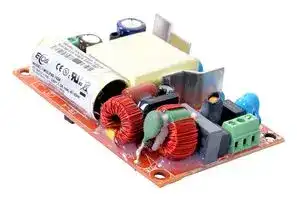
MULP40-1024
AC/DC Open Frame Power Supply (PSU), Medical, 1 Output, 40 W, 85V AC to 264V AC, Fixed
⚠️ Reference pricing provided. In case of supply shortages, we will connect you with our trusted procurement partners to ensure your project's continuity.
- Manufacturer: EOS POWER
- Product type: AC / DC Open Frame Power Supplies
- SVHC: To Be Advised
- Product Range: -
- No. of Outputs: 1 Output
- Input Voltage VAC: 85V AC to 264V AC
- Power Supply Output Type: Fixed
- Output Current - Output 1: 1.67A
- Output Current - Output 2: -
- Output Current - Output 3: -
- Output Current - Output 4: -
- Output Voltage - Output 1: 24VDC
- Output Voltage - Output 2: -
- Output Voltage - Output 3: -
- Output Voltage - Output 4: -
- Power Supply Applications: Medical
- Power Rating (Forced Cooling): -
- Power Rating (Convection Cooling): 40W
| Delivery and price | |
|---|---|
| Units per pack | 100 |
| Price | 23.17 € |
| Current stock | 10+ |
| Lead time | 30 days |
Datasheet

**40 Watt Medical**

## Features

- l 3 x 2 x 0.75 Inches Form factor

- l 40 Watts Convection

- l Approval to EN60601 3rd Edition

- l Efficiencies 85% Typical

- l -40 to 70 degree operating temperature*

- l Dual fusing

- l[2m Hours, Telcordia ][-][SR332][-][issue 3 ] MTBF

- ~~l No Load Power < 0.3W l Medical (BF) Safety Approvals l Meets standard IEC60601-1-2 : 2014 (4th Edition)~~

Electrical Specifications

**==> picture [482 x 387] intentionally omitted <==**

**----- Start of picture text -----**<br>
||||
|---|---|---|
|Input Voltage|85-264 VAC/390 VDC, Universal|
|Input Frequency|47-63 Hz|
|Input Current|115 VAC: 0.8 A max.|230 VAC: 0.4 A max.|
|No Load Power|less than 0.3W typical|
|Inrush Current|115 VAC – 25 A, 230 VAC – 45 A, 264 VAC – 75 A|
|Leakage Current|300 uA Typical, (N.A. For Class II Option)         Touch current <100uA|
|Efficiency|85% Typical|
|Hold-up Time|40W:60 ms @230VAC|
|Output Power|40W Convection Cooling|
|Line Regulation|+/-0.5%|
|Load Regulation|+/-1%|
|Transient Response|25% step load change, at 0.1A/uS slew rate, 50% duty cycle, 50/60Hz,max excursion 4%,|
|recovery time 5mS.|
|Rise Time|50ms typical|
|Set Point Tolerance|2% (3% for 5V model)|
|Over Current Protection|>110%|
|Over Voltage Protection|110 to 140%|
|Short Circuit Protection|Hiccup mode|
|Switching Frequency|65 KHz Typical|
|Operating Temperature|[4]|- 40 to +70°C, * -40 to 0°C startup is guaranteed with spec deviation|
|Storage Temperature|-|40 to +85°C|
|Relative Humidity|5% to 95%, noncondensing|
|Altitude|Operating: 16,000 ft.; Nonoperating: 40,000 ft.|
|MTBF|2m Hours, Telcordia -SR332-issue 3|
|Isolation Voltage|Input to Output – 4000 VAC medical applications.|
|Input to GND - 1500 VAC (Not Applicable For Class II Option)|
|-|
|Output to GND|1500VAC for type BF , 500 VAC for type B (Not Applicable For Class II Option)|

**----- End of picture text -----**<br>


4EM-19-180                                                                                                                                     39-DE60-44850-002 / A6

~~Option 1~~

|Model Number Description Voltage Max. Load                  Min. Load               Ripple|Model Number Description Voltage Max. Load                  Min. Load               Ripple|Max. Load                  Min. Load               Ripple1|
|---|---|---|
|MULP40-1305with Header5 V                             5A                                  0.0 A                            1.5%||5 V                             5A                                  0.0 A                            1.5%|
|MULP40-1312with Header12 V                          3.33A                                0.0 A                             1%||12 V                          3.33A                                0.0 A                             1%|
|MULP40-1315with Header15 V                          2.67A                                0.0 A                             1%||15 V                          2.67A                                0.0 A                             1%|
|MULP40-1324with Header24 V                          1.67A                                0.0 A                             1%||24 V                          1.67A                                0.0 A                             1%|
|MULP40-1330with Header30 V                          1.33A                                0.0 A                             1%||30 V                          1.33A                                0.0 A                             1%|
|MULP40-1348with Header48 V                          0.83A                                0.0 A                             1%||48 V                          0.83A                                0.0 A                             1%|
|MULP40-1358with Header58 V                          0.69A                                0.0 A                             1%||58 V                          0.69A                                0.0 A                             1%|
|MULP40-CK metal cover kit accessory|||
|MULP40-1205with PCB Mounting5 V                             5A                                   0.0 A                            1.5%<br>MULP40-1212with PCB Mounting12 V                          3.33A                                0.0 A                             1%<br>MULP40-1215with PCB Mounting15 V                          2.67A                                0.0 A                             1%<br>MULP40-1224with PCB Mounting24 V                          1.67A                                0.0 A                             1%<br>MULP40-1230with PCB Mounting30 V                          1.33A                                0.0 A                             1%<br>~~MULP40-1248with PCB Mounting              48 V                          0.83A                                0.0 A                             1%~~<br>~~MULP40-1258with PCB Mounting              58 V                          0.69A                                0.0 A                             1%~~<br> Model Number Description Voltage Max. Load                  Min. Load               Ripple1<br>~~Option 2~~<br>~~=~~|||
|~~MULP40-1005with Screw Terminal             5 V                             5A                                   0.0 A                            1.5%~~<br>~~MULP40-1012with Screw Terminal            12 V                          3.33A                                0.0 A                             1%~~<br>~~MULP40-1015with Screw Terminal            15 V                          2.67A                                0.0 A                             1%~~<br>~~MULP40-1024with Screw Terminal            24 V                          1.67A                                0.0 A                             1%~~<br>~~MULP40-1030with Screw Terminal            30 V                          1.33A                                0.0 A                             1%~~<br>~~MULP40-1048with Screw Terminal            48 V                          0.83A                                0.0 A                             1%~~<br>~~MULP40-1058with Screw Terminal            58 V                          0.69A                                0.0 A                             1%~~<br>~~MULP40-CK metal cover kit accessory~~<br> ~~Model NumberDescriptionVoltage          Max. Load                  Min. Load               Ripple1~~<br>~~Option 3~~<br>~~—~~|||
|~~Connectors~~|||
|J1 Option 1 & 3<br>Pin 1<br>AC LINE<br>Pin 2<br>NOT FITTED<br>Pin 3<br>AC NEUTRAL|||
|J2 Option 1 & 3<br>Pin 1,2<br>V1 +VE<br>Pin 3,4<br>V1 -VE<br> ~~4EM-19-180~~<br>~~39-DE60-44850-002/ A6~~||~~Innovat~~i~~ons in Power~~<br>~~**2**~~|


**==> picture [54 x 53] intentionally omitted <==**

## Notes

1. Ripple is peak to peak with 20 MHz bandwidth and 10 µF (Electrolytic capacitor) in parallel with a 0.1 µF capacitor at rated line voltage and load ranges.

2. Class II version available, Add “-II” suffix at the end of the Model Number.

3. Specifications are for nominal input voltage, 25°C unless otherwise stated.

4. Output ripple can be more than 10% of the output voltage.

5. When used in Cover Kit, de-rate output power to 70 % under all operating conditions

**==> picture [510 x 366] intentionally omitted <==**

**----- Start of picture text -----**<br>
Mechanical Specifications<br>AC Input Connector (J1) Option 1  Tyco: 640445-3<br>Mating: 647402-3; Pins: 3-647409-1<br>DC Output Connector (J2) Option 1               Tyco: 640445-4<br>                                                                        Mating: 647402-4; Pins: 3-647409-1<br>Dimensions  3 x 2 x 0.75  inches<br>                                                                        (76.20 x 50.8 x 19.05 mm)<br>Weight  100 gm approx<br>EMC<br>    Parameter  Conditions/Description      Criteria<br>Conducted Emissions EN 55011-B,CISPR22-B, FCC PART15-B Pass<br>Radiated Emissions EN 55011 A Pass<br>Level B with external core (King core K5B RC<br>25x12x15-M in input cable)<br>Input Current Harmonics EN 61000-3-2 Class A<br>Voltage Fluctuation and Flicker EN 61000-3-3 Pass<br>ESD Immunity EN 61000-4-2 Level 4, Criterion A<br>Radiated Field Immunity EN 61000-4-3 Level 3, Criterion A<br>Electrical Fast Transient Immunity EN 61000-4-4 Level 3, Criterion A<br>Surge Immunity EN 61000-4-5 Level 3, Criterion A<br>Conducted Immunity EN 61000-4-6 Level 3,  Criterion A<br>Magnetic Field Immunity EN 61000-4-8 Level 4, Criterion A<br>Voltage dips, interruptions EN 61000-4-11 Criterion  A & B<br>**----- End of picture text -----**<br>


||Safety|
|---|---|
|CE Mark|Complies with LVD Directive|
|Approval Agency|Nemko, UL, C-UL|
|SafetyStandard(s)|EN60601-1, IEC 60601-1 (ed.3), ANSI / AAMI ES 60601 - 1, CSA C22.2 No. 60601-1|
|Safety File Number(s)|Class I : Nemko: P17221669, CB: NO95698, UL: 2017-1-30-E173812|
||Class II : Nemko: P17221705, CB : NO95847, UL: 2017-01-31-E173812|


~~4EM-19-180                                                                                                                                     39-DE60-44850-002 / A6~~

**==> picture [66 x 12] intentionally omitted <==**

**----- Start of picture text -----**<br>
Derating Curve<br>**----- End of picture text -----**<br>


De-rate linearly from 100% at 50°C to 50% at 70°C

**==> picture [356 x 264] intentionally omitted <==**

**----- Start of picture text -----**<br>
Mechanical Drawing<br>Option 1<br>3.00 [76.20]<br>2.75 £0.008 [69.85+0.2] 0.125[3.175] 0.094<br>6 é [ 7 HEIGHT<br>J2— ‘N<br>+10 +Ho |1<br>-|0 ¥| © |<br>N of }<br>8| §<br>fo} N 1<br>7<br>laa [e} fo} 1<br>@@ Og 0NS= |—<br>0.593 [15.05]<br>MOUNTING HOLES<br>DIA 0.138 [3.50] 4—PLS CEN ANOVE<br>PCR .75 [19.05]<br>MECHANICAL OUTLINE DIMENSIONS<br>ALL DIMENSIONS ARE IN INCHES[MM]<br>GEN TOLERANCE : +/—0.04[+/—1.0MM]<br>Notes: In case the PCB is mounted in a metal enclosure, using metal hardware ensure the following<br>**----- End of picture text -----**<br>


1. Stand off, used to mount PCB has OD of 5.4 mm max.

2. Screws, used to fix PCB on stand off, have head dia of 6.0 mm max.

3. Washer, if used, to have dia of 6.5 mm max.

**4** Innovations in Power 39-DE60-44850-002 / A6

4EM-19-180

**==> picture [91 x 37] intentionally omitted <==**

**----- Start of picture text -----**<br>
Mechanical Drawing<br>Option 2<br>**----- End of picture text -----**<br>


Mechanical Drawing Option 3 3.00 [76.20] £0.008 [69.85+0.2] 0.125[ 3.175] 0.094 [2.4] 0.125[ 3.175] COMPONENT _ _ HEIGHT BELOW PCB ¢|—= [ J2— iS fol | +18 t re) | +16 +} © | 16 as 5 ie) i fe) [e) 1 6} © | fo) N H i od . |_ 0.593 [15.05] MOUNTING HOLES DIA 0.138 [3.50] 4—PLS TEOHT ABOVE PCB .75 [19.05] MECHANICAL OUTLINE DIMENSIONS ALL DIMENSIONS ARE IN INCHES[MM] GEN TOLERANCE : +/-0.04[+/-1.0MM] 39-DE60-44850-002 / A6

4EM-19-180
Updated at April 22, 2026
About Novapart
Novapart is a B2B electronic component broker specialising in stock shortages and cost reduction. We source hard-to-find parts and identify compliant alternatives across a catalogue of 410,000+ components from 500+ manufacturers.
Learn more →Stock Shortage Specialist
When a component is unavailable, discontinued or has an unacceptable lead time, we tap into our network of vetted European and Asian distributors to source what you need — without compromising on quality or traceability.
Request a quote →Compliant Alternatives
We identify pin-to-pin, electrically equivalent substitutes that meet the same certifications (RoHS, AEC-Q100, REACH) as your original specification — validated against datasheets, not just part numbers. Often at a lower cost.
BOM Analysis service →