
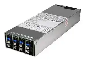


MU400PBF
AC/DC Enclosed Power Supply (PSU), O/P 5:24V, 10A, ITE, Industrial, Laboratory & Medical, 5 Outputs
- Manufacturer: TDK-LAMBDA
- Product type: AC / DC Enclosed Power Supplies
- SVHC: No SVHC (15-Jan-2018)
- Product Range: MU4 Series
- No. of Outputs: 5Outputs
- Output Power Max: 800W
- Current, Output 4: 10A
- Input Voltage VAC: 85V AC to 264V AC
- Power Supply Output Type: Fixed
- Output Current - Output 1: 2A
- Output Current - Output 2: 10A
- Output Current - Output 3: 10A
- Output Voltage - Output 1: 5V
- Output Voltage - Output 2: 24V
- Output Voltage - Output 3: 24V
- Output Voltage - Output 4: 24V
- Power Supply Applications: ITE, Industrial, Laboratory & Medical
| Delivery and price | |
|---|---|
| Units per pack | 1 |
| Price | 602.88 € |
| Current stock | 10+ |
| Lead time | 30 days |
**MU4 Series**

https://emea.lambda.tdk.com/mu https://product.tdk.com/en/power

> Medical Industrial Test Broadcast Comms Renewable

## **600W / 800W 1U Modular power supply**

## **Benefits**

|**Features**|**Benefits**|
|---|---|
|• Extremely low audible noise fan|Enhanced patient / user experience|
|• BF ready medical isolation (MOPP)<br>• Up to 5 outputs<br>• PMBus™ communication option|Eases design into systems (including BF)<br>Eliminates need for additional supplies<br>Remote monitoring and control|
|• 7year warranty|Low cost of ownership|


## **Input**

|Output power|600W|800W|
|---|---|---|
|Input voltage|85-264Vac(Contact sales for operation below 90Vac)|180-264Vac|
|Frequency<br>Input fuses<br>Inrush current<br>Leakage current<br>Touch current<br>Power factor|47 - 63 Hz (440Hz with reduced PFC)<br>10A / 250Vac HBC Fast acting(not user accessible) in both Live and Neutral lines (single fusing optional)<br><45A at 25°C and 264Vac (cold start)<br>300µA max<br><100µA<br>> 0.9(at 230Vac, 100% load)||


## **Isolation**

|Input to output / signals|Reinforced|2 x MOPPs (3rd edition 60601)<br>4kVac, 5.7kVdctype tested to 4kVac (equivalent to 5.7kVdc), production tested to 4.3kVdc.|
|---|---|---|
|Input to earth<br>Output / signals to earth<br>Output / signals to output / signals|Basic<br>Basic<br>Basic|1 x MOPP, 1.5kVac<br>1 x MOPP, 1.5kVac<br>200Vdc(1 x MOPP between modules is available,contact sales for details)|


## **How To Create A Product Description**

The extensive range of output modules and options make it possible to achieve almost any combination of Volts and Amps. You can create your own MU configuration online at https://config.emea.tdk-lambda.com/. This method checks your configuration and offers the optimum solution. Alternatively, you can do this manually by using the guide below.

**==> picture [500 x 225] intentionally omitted <==**

**----- Start of picture text -----**<br>
1.  Calculate total output power to select the appropriate converter, then select required Cooling, Input Connection, Input Fuse, Leakage<br>Current and Controls/Signals from the following table:<br>2.  Select Output Modules using the output voltages tables and the module specifications.<br>3.  Contact TDK-Lambda to validate configuration and issue a part number.<br>MU4 F S D L T5H<br>Converter MU4 [600W low line, 800W ]<br>4 slots wide high line blank none<br>E5H 5V / 2A, AC good + Enable<br>Standby<br>T5H 5V / 2A, AC good + Inhibit<br>Cooling F Variable speed F orward air - standard / Signals Q5H0000 5V / 2A, see PMBus ™  app note<br>see specification page for details<br>= Input S S crew<br>Connection<br>D Dual AC fuses<br>Input fuse E Single AC fuse in Live line(contact sales for details) Leakage Current (max at 264Vac, 63Hz) L 300µA<br>=<br>MU4_Datasheet_360017 - v3 MU4 Series 1<br>**----- End of picture text -----**<br>


MU4_Datasheet_360017 - v3

**==> picture [516 x 32] intentionally omitted <==**

|**Possible Outputs - see individual module data for full specif cations**|**Possible Outputs - see individual module data for full specif cations**|**Possible Outputs - see individual module data for full specif cations**||||
|---|---|---|---|---|---|
|**Module name**|**Slots used**|**Output voltage**|**range**|**Maximum Output**<br>**Current**|**Maximum Output**<br>**Power**|
|SB<br>ZC<br>SB<br>YC<br>YC<br>SB<br>SB<br>YC<br>YC|1<br>2<br>1<br>2<br>2<br>1<br>1<br>2<br>2|3.3V<br>-<br>3.3V<br>-<br>6V<br>-<br>6.6V<br>-<br>12V<br>-<br>15V<br>-<br>30V<br>-<br>30V<br>-<br>60V<br>-|6V<br>6V<br>15V<br>12V<br>30V<br>30V<br>52V<br>60V<br>104V|30A<br>54A<br>20A<br>30A<br>20A<br>10A<br>5A<br>10A<br>5A|150W<br>260W<br>240W<br>300W<br>480W<br>240W<br>240W<br>480W<br>480W|


Note. ‘Maximum Output Current’ and ‘Maximum Output Power’ above are the maximum available from the module. It is not possible to exceed the ‘Output Power’ of the unit given on the previous page.

MU4 Series

MU4_Datasheet_360017 - v3

2

**==> picture [516 x 32] intentionally omitted <==**

**==> picture [511 x 290] intentionally omitted <==**

**----- Start of picture text -----**<br>
Output Specification<br>Turn on time 2s max at 85Vac (180Vac for 800W) and 100% rated output power<br>Efficiency Up to 90% 230Vac, 100% rated power,  25°C, configuration dependent<br>12ms min at 600W output power (for 30-52Vdc SB module and 60 -104Vdc YC module, 9ms min)<br>Hold up<br>10ms min at 800W output power (for 30-52Vdc SB module and 60 -104Vdc YC module, 7ms min)<br>converter protection shuts down all outputs (except standby supplies) and fan, auto<br>Over temperature protection Yes<br>restarts. Shutdown temperature varies according to ambient, output power and input voltage.<br>Environment<br>Temperature -20°C to 70°C operational,  -40°C to 70°C storage.<br>Derating 50°C to 70°C derate total output power and each output current by 2.5% per °C<br>Low temperature startup -40°C, all specification parameters may not be achieved<br>Audible noise As low as 36dBA, 25°C, 115Vac/240Vac and 80% unit power (fan speed increases with load / temperature)<br>Humidity 5 - 95% RH non condensing<br>±3 x 30g shocks in each plane, total 18 shocks (11ms (+/-0.5msec), half sine)<br>Shock Conforms to EN60068-2-27, EN60068-2-47, IEC68-2-27, IEC68-2-47, JIS C0041-1987.<br>Conforms to MIL-STD-810G, Method 516.6, Pro IV<br>Single axis 10 - 500 Hz at 2g (sweep and endurance at resonance) in all 3 planes<br>Vibration Conforms to EN60068-2-6, IEC68-2-6<br>Conforms to MIL-STD-810G, Method 514.6, Pro I<br>Altitude 5000 metres operational (4000 metres for 60601-1), 5000 metres storage/transportation<br>Pollution Degree 2, Material group IIIb<br>IP Rating IPX0<br>**----- End of picture text -----**<br>


|**Emissions EN61000-6-3:2007, EN60601-1-2:2015 - see application notes for best installation practice**|**Emissions EN61000-6-3:2007, EN60601-1-2:2015 - see application notes for best installation practice**|**Emissions EN61000-6-3:2007, EN60601-1-2:2015 - see application notes for best installation practice**|
|---|---|---|
|Radiated electric feld|EN55011, EN55032|(as per CISPR.11/32) Class B, FCC47 part 15 subpart B -‘L’ leakage current variants|
|Conducted emissions<br>Conducted harmonics<br>Flicker|EN55011, EN55032<br>EN61000-3-2<br>EN61000-3-3|(as per CISPR.11/32) Class B, FCC47 part 15 subpart B -‘L’ leakage current variants<br>Class A and Class C<br>Compliant - dmaxonly|


**==> picture [511 x 167] intentionally omitted <==**

**----- Start of picture text -----**<br>
Immunity EN61000-6-2:2005, EN60601-1-2:2015 - see application notes for best installation practice Criteria<br>Electrostatic discharge EN61000-4-2 Level 4 F type cooling only A<br>Proximity fi elds, EN60601-1-2, Levels as defi ned in<br>Electromagnetic fi eld EN61000-4-3 Level 3 A<br>standard, Criteria A<br>Fast / burst transient EN61000-4-4 Level 4 Tested at 5kHz and 100kHz A<br>Surge immunity EN61000-4-5 Level 3 A<br>Conducted RF immunity EN61000-4-6 Level 3 A<br>Power frequency magnetic fi eld EN61000-4-8 Level 4 A<br>Voltage dips, variations, interruptions EN61000-4-11 Class 3 Criteria B for 5s and 1 cycle interruptions A<br>Voltage sags Semi F-47 compliant above 180Vac input<br>Ring wave EN61000-4-12 Level 3 A<br>Voltage fl uctuations EN61000-4-14 Class 3 See EMC report for full details. A<br>**----- End of picture text -----**<br>


## **Approvals / Accreditations**

**==> picture [511 x 133] intentionally omitted <==**

**----- Start of picture text -----**<br>
IEC/EN 62368-1, UL62368-1 / CSA 22.2 No 62368-1 File E135494<br>IEC/EN 60950-1, UL60950-1 / CSA 22.2 No 60950-1 File E135494<br>IEC/EN 60601-1, UL/CSA 60601-1, ANSI/AAMI ES60601-1, CAN/CSA-C22.2 No 60601-1 File E349607<br>IEC/EN 61010-1 Designed to meet<br>Low Voltage Directive (LVD), electromagnetic compatibility (EMC) and Restriction<br>CE Mark  (EN62368-1)<br>of Hazardous Substances (RoHS)<br>Electrical Equipment (Safety) Regulations, electromagnetic compatibility (EMC)<br>UKCA  (EN62368-1)<br>and Restriction of Hazardous Substances (RoHS)<br>CB certifi cate and Report available on request<br>Designed and manufactured under the control of ISO9001 and ISO13485 (including risk management).<br>**----- End of picture text -----**<br>


MU4 Series

3

MU4_Datasheet_360017 - v3

**==> picture [516 x 32] intentionally omitted <==**

|**Standby / Signals**||
|---|---|
|Maximum power per channel|See table below|
|Available signals (Exx or Txx type)|PSU inhibit (Txx ty~~pe)~~ ~~or enable (Ex~~x t~~ype), ACGood~~|
||PMBus™ control o~~f po~~wer sup~~p~~ly|
|Available signals (Qxx type)|fan speed and fail~~warn~~ing<br>Serial numbe~~r,~~date~~of~~ ~~m~~a~~n~~uf~~a~~ctur~~e,~~ru~~n~~ ~~t~~im~~e~~, on~~/o~~f ~~p~~o~~w~~e~~r~~cy~~cles~~|
||For further details,~~see~~ ~~the produ~~c~~t r~~a~~nge appl~~i~~c~~a~~tion notes,~~ ~~PMB~~u~~s™ sec~~ti~~o~~n|


|**Available Output Voltages (at PSU signal con-**|**Available Output Voltages (at PSU signal con-**|**Available Output Voltages (at PSU signal con-**|**Available Output Voltages (at PSU signal con-**|
|---|---|---|---|
|||**nector)**||
|**Option**<br>**type**|**V**|**Standby 1**<br>**Max**<br>**Current**<br>**Power**|**PSU on/of**|
|E5H|5V|2A<br>10W|Enable|
|T5H|5V|2A<br>10W|Inhibit|
|Q5H0000|5V|2A<br>10W|see PMBus™<br>application note|


**==> picture [168 x 279] intentionally omitted <==**

**----- Start of picture text -----**<br>
Conector i nf ormation<br>10 way housing Molex 51110-1060<br>12way housing Molex 51110-12 60<br>Crimp terminal Molex 50394<br>Txx or Exx o p t ion<br>Pin 5H<br>1 Standby +<br>2 S tand by - PI N  2<br>3 Do  no t c onn ec t<br>4 D o  n ot  co nn e c t PIN 1<br>5 PS U on/off+<br>6 PSU  on/off-<br>7 A C fai l Out<br>8 AC  fail Rtn<br>9 Fan fail Out<br>1 0 Fan fail Rtn<br>PIN 9<br>PIN 10<br>Pin Q5Hxxxx option<br>1 Standby +<br>2 Standby -<br>3 Do not connect PIN 1 PIN 2<br>4 Fan fail<br>5 Address 0<br>6 Address 1<br>7 Address 2<br>8 Address 3<br>9 SCL - Clock<br>10 SDA - Data<br>11 Control line in<br>12 GND<br>PIN 11 PIN 12<br>**----- End of picture text -----**<br>


## **Output Specification**

**==> picture [462 x 195] intentionally omitted <==**

**----- Start of picture text -----**<br>
Rise time <30ms (with resistive l oad) to 90% of voltage, monotonic  rise above 10%<br>Ripple and noise <2% pk-pk, using 20MHz bandwidth<br>Voltage setting accuracy <3% of set voltage<br>Remote sense No<br>Minimum load 0W on any output<br>Temperature coefficient 0.02% of rated voltage per °C<br>Load regulation <1.0% for 0-100% load change<br>Line regulation <0.1% for 90-264Vac input change<br>Cross regulation <0.4% for 100% load change on any output<br>Transient deviation <5% of set voltage for 25-50% load change<br>Recovery 1ms for recovery to 1% or 100mV of set voltage<br>Over voltage protection Yes Latching, output shuts down, cycle ac to reset<br>Over current protection Constant Current Auto recovers<br>Short circuit protection Constant Current Auto recovers<br>**----- End of picture text -----**<br>


MU4 Series

MU4_Datasheet_360017 - v3

4

**==> picture [516 x 32] intentionally omitted <==**

## **SB Module - single slot width, 1 output channel**

Maximum power per channel see table below Available signals Remote sense, module good, module inhibit or enable (Note 1:)

**==> picture [512 x 161] intentionally omitted <==**

**----- Start of picture text -----**<br>
Conector information<br>10 way housing Molex 51110-1060<br>Crimp terminal Molex 50394<br>AVAILABLE OUTPUT VOLTAGES (at PSU output terminals) Pin Connection<br>1 Remote Sense +<br>Adjustment Range (Volts) Current Output power Max Capaci-tive Load 2 10 23 Current share (Note: 1)Remote Sense -<br>4<br>3.3 - 6.0 30A 150W 500µF/A 5 Do not connect<br>1 9 6<br>6 - 15 20A 240W 500µF/A V ADJ 7 Module good collector<br>15 - 30 10A 240W 500µF/A CH1 + 89 Module enable/inhibit Module good emitter<br>30 - 52 5A 240W 200µF/A anode<br>10 Module enable/inhibit<br>cathode<br>Note 1: Current share is only available on ZC module pair CH1 -<br>**----- End of picture text -----**<br>


## **Output Specification**

**==> picture [512 x 273] intentionally omitted <==**

**----- Start of picture text -----**<br>
Rise time <75ms (with resistive load) to 90% of voltage, monotonic rise above 10%<br>Turn on overshoot <5% Load type dependent<br>Ripple and noise max of pk-pk, using 20MHz bandwidth<br>0°C - 70°C, >5% load 1% or 50mV 2% above 6V output<br>-20°C - 0°C, >5% load 2% or 100mV 2% above 6V output<br>≤5% load 4%<br>Voltage setting accuracy <1% of set voltage<br>Remote sense Option 0.5V (voltage at the output terminals must remain within the adjustment range specified above)<br>Minimum load 0W<br>Temperature coefficient 0.02% of rated voltage per °C<br>Load regulation <1% for 0-100% load change<br>Line regulation <0.1% for 90-264Vac input change<br>Cross regulation 0.1% (5mV for outputs below 5V) for 100% load change on any output<br>of set voltage for 25% to 75% load change<br>Transient deviation <5%<br>250mV for outputs below 5V<br>Recovery 1ms for recovery to 1% or 100mV of set voltage (between 6V  and 30V recovery is 1.5ms)<br>Over voltage protection Yes Latching, module shuts down, cycle ac to restart.<br>Over current protection Hiccup Auto recovers after removal of load<br>Short circuit protection Yes Indefinitely protected, see application notes for details<br>Over temperature protection Yes Module protection shuts down output, cycle ac to restart.<br>Shutdown temperature varies according to ambient, output power and input voltage.<br>**----- End of picture text -----**<br>


## **How To Create A Product Description**

Choose your required output voltage (from the table above)

For example, if you need 12V / 20A with remote sense, you would choose **12SBSF or G** as your required module.

**==> picture [485 x 100] intentionally omitted <==**

**----- Start of picture text -----**<br>
L none<br>V1 SB S L<br>F [Remote sense, Output enable, ]<br>output good (including LED)<br>Module<br>Required output voltage Option<br>G [Remote sense, Output inhibit, ]<br>output good (including LED)<br>Output<br>Module type S Screw terminal<br>connection<br>**----- End of picture text -----**<br>


MU4 Series

5

MU4_Datasheet_360017 - v3

**==> picture [516 x 32] intentionally omitted <==**

**YC Module - two slots width, 1 output channel** Maximum power per channel see table below Available signals Module good, module inhibit or enable

**==> picture [512 x 166] intentionally omitted <==**

**----- Start of picture text -----**<br>
Conector information<br>10 way housing Molex 51110-1060<br>Crimp terminal Molex 50394<br>AVAILABLE OUTPUT VOLTAGES (at PSU output terminals)<br>Max Capaci- See application<br>Adjustment Range (Volts) Current Output Power<br>tive Load notes for signal<br>6.6 - 12 30A 300W 500µF/A connection details<br>12 - 30 20A 480W 275µF/A<br>30 - 60 10A 480W 200µF/A V ADJ<br>See application notes<br>60 - 104 5A 480W 100µF/A before adjusting<br>Ch1 +<br>Ch1 0V<br>**----- End of picture text -----**<br>


## **Output Specification**

**==> picture [512 x 263] intentionally omitted <==**

**----- Start of picture text -----**<br>
Rise time <75ms (with resistive load) to 90% of voltage, monotonic rise above 10%<br>Turn on overshoot <5% Load type dependent<br>Ripple and noise pk-pk, using 20MHz bandwidth<br>0°C - 70°C, >5% load 1% 2% above 12V output<br>-20°C - 0°C, >5% load 2%<br>≤5% load 4%<br>Voltage setting accuracy <1% of set voltage<br>Remote sense Option 0.5V (voltage at the output terminals must remain within the adjustment range specified above)<br>Minimum load 0W<br>Temperature coefficient 0.02% of rated voltage per °C<br>Load regulation <1% for 0-100% load change<br>Line regulation <0.1% for 90-264Vac input change<br>Cross regulation 0.1% (10mV for outputs below 10V) for 100% load change on any output<br>Transient deviation <5% of set voltage for 25% to 75% load change<br>Recovery 1ms for recovery to 1% or 100mV of set voltage<br>Over voltage protection Yes Latching, module shuts down, cycle ac to restart.<br>Over current protection Hiccup Auto recovers<br>Short circuit protection Yes Indefinitely protected, see application notes for details<br>Over temperature protection Yes Module protection shuts down output, cycle ac to restart.<br>Shutdown temperature varies according to ambient, output power and input voltage.<br>**----- End of picture text -----**<br>


## **How To Create A Product Description**

Choose your required output voltage (from the table above)

For example, if you need 60V / 5A with remote sense, you would choose **60YCSG** as your required module.

|||**V1**<br>**YC**<br>**S**<br>**L**<br>**Out**<br>**conne**<br>**Modul**<br>**Option**|
|---|---|---|
|||**V1**<br>**YC**|
||||
|**Required output voltage**|||
||||
||||
|**Module type**|||


MU4 Series

MU4_Datasheet_360017 - v3

6

**==> picture [516 x 32] intentionally omitted <==**

**ZC Module - two slots width, 1 output channel** Maximum power per channel see table below Available signals Module good, module inhibit or enable

**==> picture [511 x 164] intentionally omitted <==**

**----- Start of picture text -----**<br>
Conector information<br>10 way housing Molex 51110-1060<br>Crimp terminal Molex 50394<br>AVAILABLE OUTPUT VOLTAGES (at PSU output terminals)<br>Adjustment Range (Volts) Current Output Power [Maximum ca-]<br>pacitive load<br>3.3 - 6 54 260W 500µF/A<br>Ch1 + V ADJ<br>See application notes<br>before adjusting<br>See application<br>notes for signal<br>connection details<br>Ch1 0V<br>**----- End of picture text -----**<br>


## **Output Specification**

**==> picture [511 x 263] intentionally omitted <==**

**----- Start of picture text -----**<br>
Rise time <75ms (with resistive load) to 90% of voltage, monotonic rise above 10%<br>Turn on overshoot <5% Load type dependent<br>Ripple and noise pk-pk, using 20MHz bandwidth<br>0°C - 70°C, >5% load 1%<br>-20°C - 0°C, >5% load 2%<br>≤5% load 4%<br>Voltage setting accuracy <1% of set voltage<br>Remote sense Option 0.5V (voltage at the output terminals must remain within the adjustment range specified above)<br>Minimum load 0W<br>Temperature coefficient 0.02% of rated voltage per °C<br>Load regulation <5% for 1-100% load change<br>Line regulation <0.1% for 90-264Vac input change<br>Cross regulation 0.1% for 100% load change on any output<br>Transient deviation <5% of set voltage for 25% to 75% load change<br>Recovery 30ms for recovery to 1% or 100mV of set voltage<br>Over voltage protection Yes Latching, module shuts down, cycle ac to restart.<br>Over current protection Hiccup Auto recovers after removal of load<br>Short circuit protection Yes Indefinitely protected, see application notes for details<br>Over temperature protection Yes Module protection shuts down output, cycle ac to restart.<br>Shutdown temperature varies according to ambient, output power and input voltage.<br>**----- End of picture text -----**<br>


## **How To Create A Product Description**

Choose your required output voltage (from the table above)

For example, if you need 3.3V / 54A with remote sense, you would choose **3.3ZCSJ** as your required module.

|||||||||||||||
|---|---|---|---|---|---|---|---|---|---|---|---|---|---|
||||**V1**||**ZC**||**S**||**J**|||**J**|Default - Remote sense,<br>Output inhibit, output good|
|**Required**|**output voltage**|||||||||||**Module**<br>**Option**<br>**H**|(includingLED),current share<br>Remote sense, Output enable,<br>output good (including LED),<br>current share|
||**Module type**|||||||||||**Output**<br>**connection**<br>**S**<br>Screw terminal||


MU4 Series

7

MU4_Datasheet_360017 - v3

**==> picture [516 x 32] intentionally omitted <==**

**==> picture [512 x 292] intentionally omitted <==**

**----- Start of picture text -----**<br>
GLOBAL OPTION SLOT<br>SLOT 1<br>SLOT 2<br>SLOT 3<br>SLOT 4<br> 254.0 MAX<br> 257.5<br>Standard<br>airflow<br> 31.5 TYP<br> 187.50 TYP<br>UNDERNEATH VIEW OF FIXINGS (M4, MAX THREAD PENETRATION 4.0mm)<br>DIMENSION TOLERANCES: 0.00 ±0.2  0.0±0.4<br>RECOMMENDED TORQUE: M4 1.1 - 1.3Nm<br>Units with factory fitted fan (‘F’ type cooling)<br> 89.0 MAX<br> 41.0 MAX<br> 69.00   62.00<br> 6.50<br> 8.5<br>**----- End of picture text -----**<br>


MU4 Series

MU4_Datasheet_360017 - v3

8

## **TDK-Lambda France SAS**

Tel: +33 1 60 12 71 65 tlf.fr-powersolutions@tdk.com www.emea.lambda.tdk.com/fr

## **TDK-Lambda Americas**

Tel:  +1 800-LAMBDA-4 or 1-800-526-2324 tla.powersolutions@tdk.com www.us.lambda.tdk.com

## **Italy Sales Office**

Tel: +39 02 61 29 38 63 tlf.it-powersolutions@tdk.com www.emea.lambda.tdk.com/it

## **Netherlands**

## **TDK Electronics do Brasil Ltda**

Tel: +55 11 3289-9599 sales.br@tdk-electronics.tdk.com www.tdk-electronics.tdk.com/en

tlf.nl-powersolutions@tdk.com www.emea.lambda.tdk.com/nl

## **TDK-Lambda Germany GmbH**

Tel: +49 7841 666 0 tlg.powersolutions@tdk.com www.emea.lambda.tdk.com/de

## **TDK-Lambda Corporation**

Tel: +81-3-6778-1113 www.jp.lambda.tdk.com

## **TDK-Lambda (China) Electronics Co. Ltd.**

Tel: +86 21 6485-0777 tlc.powersolutions@tdk.com www.lambda.tdk.com.cn

## **Austria Sales Office**

Tel: +43 2256 655 84 tlg.at-powersolutions@tdk.com www.emea.lambda.tdk.com/at

## **Switzerland Sales Office**

Tel: +41 44 850 53 53 tlg.ch-powersolutions@tdk.com www.emea.lambda.tdk.com/ch

## **Nordic Sales Office**

## **TDK-Lambda Singapore Pte Ltd.**

Tel: +65 6251 7211 tls.marketing@tdk.com www.sg.lambda.tdk.com

## **TDK India Private Limited, Power Supply Division**

Tel:   +91 80 4039-0660 mathew.philip@tdk.com www.sg.lambda.tdk.com

Tel: +45 8853 8086 tlg.dk-powersolutions@tdk.com www.emea.lambda.tdk.com/dk

## **TDK-Lambda UK Ltd.**

Tel: +44 (0) 12 71 85 66 66 tlu.powersolutions@tdk.com www.emea.lambda.tdk.com/uk

## **TDK-Lambda Ltd.**

Tel: +9 723 902 4333 tli.powersolutions@tdk.com www.emea.lambda.tdk.com/il-en

For Additional Information, please visit https://product.tdk.com/en/power/

MU4 Series

9

MU4_Datasheet_360017 - v3
Updated at June 4, 2026
TDK-Lambda is globally recognized as a premier manufacturer of highly reliable power supply solutions and power management equipment. With a strong engineering heritage, the company is a trusted partner for mission-critical applications across the industrial, medical, telecommunications, and test and measurement sectors, delivering components that meet stringent international performance and safety standards. Our extensive portfolio of TDK-Lambda products is heavily focused on comprehensive power and line protection, highlighted by a vast selection of industry-leading AC/DC converters. Engineered to deliver exceptional efficiency and stable performance in demanding environments, these power supplies form the backbone of our offering and are built to support the rigorous power demands of modern electronic infrastructure. To complement these primary power solutions, we also offer a targeted range of high-performance DC/DC converters designed for precise, board-level voltage regulation. Furthermore, to ensure the optimal performance and longevity of these power systems, our catalog includes specialized cooling and thermal management components, such as natural convection heat sinks, providing complete thermal stability for your most critical designs.
About Novapart
Novapart is a B2B electronic component broker specialising in stock shortages and cost reduction. We source hard-to-find parts and identify compliant alternatives across a catalogue of 410,000+ components from 500+ manufacturers.
Learn more →Stock Shortage Specialist
When a component is unavailable, discontinued or has an unacceptable lead time, we tap into our network of vetted European and Asian distributors to source what you need — without compromising on quality or traceability.
Request a quote →Compliant Alternatives
We identify pin-to-pin, electrically equivalent substitutes that meet the same certifications (RoHS, AEC-Q100, REACH) as your original specification — validated against datasheets, not just part numbers. Often at a lower cost.
BOM Analysis service →