
Image not available
Illustrative purposes only

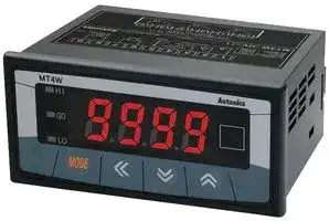
MT4W-DV-1N
DIGITAL PANEL METER, 4-DIGIT, 12VDC TO 24VDC
⚠️ Reference pricing provided. In case of supply shortages, we will connect you with our trusted procurement partners to ensure your project's continuity.
- Manufacturer: AUTONICS
- Product type: Digital Panel Meters
- No. of Digits / Alpha:4; Meter Function:DC Voltage; Meter Range:0V to 500V; Digit Height:14.2mm; Panel Cutout Height:45mm; Panel Cutout Width:92mm; Supply 22T2535
- Meter Range: 0V to 500V
- Digit Height: 14.2mm
- Product Range: MT4W Series
- Meter Function: DC Voltage
- Panel Cutout Width: 92mm
- Supply Voltage Max: 24VDC
- Supply Voltage Min: 12VDC
- Panel Cutout Height: 45mm
- No. of Digits / Alpha: 4
- Operating Temperature Max: 50°C
- Operating Temperature Min: -10°C
| Delivery and price | |
|---|---|
| Units per pack | 1 |
| Price | 106.27 € |
| Current stock | 50+ |
| Lead time | 30 days |
Datasheet

MT4Y/MT4W Series

**==> picture [508 x 36] intentionally omitted <==**

**----- Start of picture text -----**<br>
I<br>DIN W72<H36mm, W96 x 48mm, digital multi panel meter<br>**----- End of picture text -----**<br>


**==> picture [494 x 196] intentionally omitted <==**

**----- Start of picture text -----**<br>
(=|Features<br>@Various output options (Default : Indicator)<br>RS485 Communication output, Low speed serial output,<br>Current (4—-20mA), BCD output, NPN/PNP open collector<br>output, Relay output * : —<br>@Max. measuring input specification : ce ff<br>500VDC, 500VAC, DC5A, ACSA = =en Se.<br>@ Max.High/Lowdisplayscale rangefunction: —1999 ~ 9999 i EEEE]ie } | eeif) i470 oy<br>@AC frequency measurement function : 0.1~9999Hz 7S |e j oe |<br>@Various functions : Monitoring function for max. and a<br>min. display value function, Display cycle delay function,<br>Zero function, High display correction function,<br>Current output scale function<br>@Wide range of power supply : 12—24VDC, 100-—240VAC<br>Please read "Caution for your safety" in operation C  € cdsTAL<br>**----- End of picture text -----**<br>


**==> picture [509 x 491] intentionally omitted <==**

**----- Start of picture text -----**<br>
@™Ordering information<br>|4 | [Ww] - [Dv] — [4]<br>SSCS<br>Fo [Relay contactoutput<br>Y Type<br>[6 [Low speed serial ouiout<br>Output * OutputSSCS(O~6) : Option<br>0" [Reiay contact eutpur+ Transmssion outButTOGA=2OmA)<br>W Type PNP open collector output+BCD —Dynamic output<br>[6 [NPW open colector output+Low speed seal cutout<br>Pa |NPN open colector ouipureASé@s outout +<br>[3 [PNP open collector outputtASA85 output ——*t<br>%* Output (O~9) : Option<br>Power supply<br>Digit<br>* To measure the current over 5ADC, please select DV type because the shunt should be used.<br>—SSS<br>E-23 Autonics<br>**----- End of picture text -----**<br>


**==> picture [528 x 776] intentionally omitted <==**

**----- Start of picture text -----**<br>
Multi Panel Meter<br>eee<br>Specifications<br>Seri MT4Y-DV-47 | MT4Y-AV-4(7 |MT4W-DV-4(2) |MT4W-AV-4L) | MT4W-DV-100 | MT4W-AV-1()<br>eries MT4Y-DA-4( | MT4Y-AA-40 |MT4W-DA-47 |MT4W-AA-4C | MT4W-DA-100| MT4W-AA-10<br>Measurement function VDC, ADC VAC, AAC, VDC, ADC VAC, AAC, VDC, ADC VAC, AAC,<br>Frequency Frequency Frequency<br>Power suppl 100-240VAC 50/60Hz 12-24VDC<br>PPly (90 ~ 110% of rated voltage) (90 ~ 110% of rated voltage)<br>Display method 7Segment LED Display (Red) (Character height:14.2mm)<br>DC Type & Voltage/Current : 0.1% F.S +2Digit<br>230 +50 AC Type & Voltage/Current : 0.3% F.S +3Digit, Frequency : 0.1% F.S + 2Digit<br>Display 35~85%RH When £0.3% F.S +3Digit only for 5A When +1.0% F.S +83Digit only for 5A<br>accuracy terminal of MT4Y—DA, AA Type terminal of MT4W—DA, AA Type<br>~10°C~50° DC/AC Type & Voltage/Current:0.5% F.S +3Digit}DC/AC Type  Voltage/Current: +0.5% F.S +3Digit<br>Frequency: +0.1% F.S +2Digit Frequency: +0.1% F.S +2Digit<br>A/D conversion method Practical Over sampling using successive approximation ADC (E)<br>DC type:50ms, AC type:16.6ms (Resolution 1/12000) vance<br>110% for input specification<br>* Contact capacity : 250VAC 3A, 30VDC 3A + Contact composition: N.O (La)<br>Main Mollecter butput<br>output 12-24VDC +2V 50mA Max. (Resistive load)<br>PNP open<br>collector output<br>RS485 commu-— ¢ Baud rate : 1200/2400/4800/9600bps ¢ Communication type : 2 wires half duplex<br>Sub |nication output * Protocol : RTU type ¢ Tuning method : Sub-synchronization<br>uPio TSeral output | NPN open collector output, 12-—24VDC Max. 50mA (Resistive_ load)<br>mission<br>oe” TDC4—20mA output Resolution : 12000 division (Load resistance max. 6002)<br>Selectable RMS or AVG<br>Hold function Including (Outer hold function)<br>Min. 100M (at 5OOVDC mega) between external terminal and case<br>2000VAC for lminute between external terminal and case<br>+2kV the square wave noise (pulse width:1lys) by the noise simulator<br>0.75mm amplitude at frequency of 10 ~ 55Hz in each of X, Y, Z directions for 2hours<br>eeration 0.5mm amplitude at frequency of 10 ~ 55Hz in each of X, Y, Z directions for 10minutes<br>Shockoc 100m/s?; (10G) in, X, Y, Z directions: , for 3 times,<br>300m/s* (30G) in X, Y, Z directions for 3 times<br>Relay Min. 20,000,000 times<br>life cycle | Mechanical Min. 100,000 times (250VAC 3A Load current)<br>—10 ~ +50 (at non—freezing status)<br>—20 ~ +60 (at non—freezing status)<br>Ambient humidity 35 ~ 85%RH<br>approvalP CE A<br>|/Front panel identification<br>@MTA4Y Series @MT4W Series<br>owHI ne) a MT4WHI Rotonies<br>= i m o<br>aL EEEEIMOE KK YA S | H 5S9S R |<br>eee ME K& VY A@®<br>HI : High output indication of preset key : Enter to parameter group, Memorize the setting value,<br>GO : GO output indication of preset Move the parameter mode<br>LO : Low output indication of preset )[<] key : Move the digit, Enter to parameter group<br>[vy]. [A] key : Change the setting value.<br>6) Unit sticker<br>* There is no (4), (2), (3) on a display panel of MT4Y-—LILJ-4N, 45, 46 and MT4W-LILJ-4N.<br>*In MT4Y-LIL1-438, 44, OUT is used for Go output display and there is no (J), (3) in display panel.<br>Autonicse E-24<br>**----- End of picture text -----**<br>


MT4Y/MT4W Series ~~IE~~

**==> picture [399 x 203] intentionally omitted <==**

**----- Start of picture text -----**<br>
(a]Connections<br>©OMeasuring input connection of MT4Y series<br>eMT4Y-DV-4_) eMT4Y-AV-4<br>j1[2]}3}a}sje]7 j1[2]3}4]sj6]7<br>250mV<br>A bout sourcedN A 7 20vliov source AN<br>A 50V/10V 15 0 /60Hz0—240VAC5VA A 110V/50V 15 0 /60Hz0-240VAC5VA<br>500V/100V 500V/250V<br>eMT4Y-DA-4() eMT4Y-AA-4/]<br>1} 2] 3/4/5]6]7| }1/ 2/3] [4/5/6]7|]<br>5mA AC100mA<br>oma Lo /50mA Lo!<br>50mA/ sourceAN acsooma_t Z\ SOURCE<br>A 4-20mA 100-—240VAC /AC250mA | 100-240VAC<br>A 500mA/200mA 50/60Hz 5VA A ACIA 50/60Hz 5VA<br>5A/2A AC5A/2.5A<br>**----- End of picture text -----**<br>


**==> picture [509 x 512] intentionally omitted <==**

**----- Start of picture text -----**<br>
©OOutput terminal of connection of MT4Y Series<br>eMT4Y-LILJ-4N (Indicator) eMT4Y-(1L1-40 eMT4Y-_jLJ-41<br>(Triple relay contact output) (Triple NPN O.C output)<br>(1] 2/3] 4/5] 6|7| pan sola Zer0 Hold/Zer0<br>HI GO LO COM HI GO LO com<br>eMT4Y-LIL1-42 eMT4Y-L1L1-43 eMT4Y-j_1-44<br>(Triple PNP O.C output) (Relay output+Current output) (Relay+RS485 communication output)<br>Hold/Zero DC4-20mMA OUT1  laizero OUT1 —_Hold/Zero<br>HI GO LO COM Load 6002 max.<br>eMT4Y-L11-45 @MT4Y-(ILJ-46(Low speed serial output)<br>(BCD Dynamic output) HoLo/zeRo 8 | 9 |10]14|12/13)<br>| 2 | | 4 | G | 8 | 10)f14) (_C NN V2 _ #4 PCB ee Hold/Zero<br>AK Chk DOK D2k DoT MLC 33> + <<< CLOCK DATA LATCH POL COM<br>mT) sao 3%*POL : When a display value is "—", the signal<br>com| B DP D1 D3 POL oO ® 6)@ © a) a) of "—" will be outputted.<br>1 | | 3 | [5 | | 9 | [11 13] % Hirose connector pin header model of the unit : HIFSBA—-14PA-—2.54DS<br>(Note) There is no signal output terminal Contact Hirose Electric to purchase socket and wires of Hirose connector.<br>about — sign. [Socket : HIF3BA-14D-2.54R]<br>©OMeasuring input connection of MT4W Series<br>eMT4W-DV-4) eMT4W-AV-4()<br>t]2}3f4a}sjej7)a}o jt}2}3ia}sjej7/alo<br>250mV © 2v/tV Lo!<br>/50mV A<br>5V/1V Hold/Zero Source A 20V/10V Hold/Zero Source A<br>A Sov/10V 100-240VAC A 110V/50V 100-240VAC<br>500V/100V 50/60Hz 5VA 500V/250V 50/60Hz 5VA<br>eMT4W-DA-4( eMT4W-AA-4()<br>jt}? }3]4a}sje}7)a}o 1j2|}3}ais|ej7/alo<br>5mA La) 100mA Lo!<br>/2mA 00 © /50mA OO ©<br>4-20mA50mA/ Hold/Zero 12-24VDCsource A /250mA500mA Hold/Zero 12-24VDCsourceA<br>500mA/ 100-—240VAC 1A 100-—240VAC<br>A 200mA 50/60Hz 5VA A sAlD.oa; 50/60Hz 5VA<br>5A/2A<br>eeerenee E-25 rere renee Autonicse<br>**----- End of picture text -----**<br>


**==> picture [528 x 774] intentionally omitted <==**

**----- Start of picture text -----**<br>
Multi Panel Meter<br>eee<br>©OOutput terminal connection of MT4W Series<br>@eMT4W-(1L1-40 (Triple relay contact output eMT4W-(ILI-41 (Triple relay contact output)<br>+Current output)<br>MAIN OUT MAIN OUT<br>CONTACT OUT CONTACT OUT<br>:250VAC 3A 1a RESISTIVE LOAD :250VAC 3A 1a RESISTIVE LOAD<br>| HI GO LO com bed-2108d 6 0 08mA Max. | alomt alteo akre<br>[1 ) (2) (3) 4) 5) Le) 7) Le) (2) [1] [2] [3] C4] [5] Le) [7] Le) [9]<br>_————— SSN ZZ} PB 4<br>| ML| O t ft ztz i zsii:TT GO | MMLC)ULIO44 2Sx  psi!  <<<=> _KT CI Panelmeter<br>[1] [2] [3] [4] [5] [6] [9] % HiroseDOOD®connector pinW445 header model of the unit : HIFS3BA-—20PA-2.54DS<br>* Contact Hirose Electric to purchase socket and wires of Hirose connector.<br>[Socket : HIFSBA—20D-2.54R]<br>eMT4W-(LIL1-42 / MT4W-L1L1-43 (triple NPN/PNP open collector output+BCD output)<br>+24VDC +24VDC<br>30mA Max. 5 D D1 D3 DOT Ccom2 30mA Max.<br>NPN OPEN COLLECTOR PNP OPEN COLLECTOR<br>12-24VDC Max. 50mA [3] [5 [9] (15 12-24VDC Max. 50mA 3] [5]<br>| HK Lox reBCD OUT: POL [Hix Lox wv<br>NPN OPEN COLLECTOR POL: Whena display value is "—", the signal<br>12-24VDC Max. 50mA of "—" will be outputted.<br>eMT4W-(LILI-44/ MT4W-(IL-45 (Triple NPN/PNP open collector output+Current output)<br>+24VDC +24VDC<br>30mA Max. (-) 30mA Max.<br>MAIN OUT: [2] [4] [6] fl [12] MAIN OUT: [2] [4] [s] [8]<br>NPN OPEN COLLECTOR PNP OPEN COLLECTOR<br>12-24VDC Max. 50mA [3] [5] [9] [15] 12-24VDC Max. 50mA 3] [5]<br>Cr Current: meog<br>DC4-20mA LOAD 6002 Max.<br>eMT4W-LILI-46/ MT4W-(IL-47 (triple NPN/PNP open collector output+Low speed serial output)<br>3%*POL : When a display value is "—", the signal<br>+24VDC of "—" will be outputted. +24VDC<br>30mA Max. POL CLOCK LATCH 30mA Max.<br>2} [4] [e] [8] Go b2] 4) fre] fe] fad [2] [4] [6] [8]<br>MAIN MAIN OUT :<br>NPN  OUT: PNP OPEN COLLECTOR<br>Me O O PEND  COLLECTORMn SoA [3] [5] [9] [15] [19]19] | 12-24vDCa Max. 50mA [3] [5]<br>ov ov<br>SERIAL OUT:<br>NPN OPEN COLLECTOR<br>12-24VDC Max. 50mA<br>eMT4W-(LILI-48/ MT4W-(CIL-49 (triple NPN/PNP open collector output+RS485 output)<br>+24VDC +24VDC<br>30ma  RS485 30mA Max.<br>Max. B(-)<br>MAIN OUT : [2] [4] [6] [8] fo fr] MAIN OUT : 2] 4 [e) fe<br>NPN OPEN COLLECTOR PNP OPEN COLLECTOR<br>12-24VDC Max. 50mA _ 7] 7]<br>day<br>mage gues ol<br>RS485<br>Autonicse E-26<br>**----- End of picture text -----**<br>


**==> picture [508 x 719] intentionally omitted <==**

**----- Start of picture text -----**<br>
MT4Y/MT4W Series<br>eee<br>f=|Dimensions (Unit:. mm)<br>e@eMT4Y—-LILJ-AN, 45, 46<br>85 83<br>72 6 65 12<br>| | | @Panel cut-out<br>g ~OOO0 © _ LJ Min.91<br>wo ale el, oll, g oO SS == = B oO ><br>MTAY mone << Wm S-_ SS Vv 108<br>emT4y-CIL-43, <MT4Y—-LILJ-4N, 40~44, 46> Min. 40 6g 127<br>ea = = =442 1 ~<br>»OoOoo 83<br>MTA 3.43.3.none < WN a 10 PinwsHirose connector<br>(HIF3BD—10PA—2.54DS)<br>emT4y-CIC1-40, 41, 42 7 a<br>ee = = = 2 SS— OE55 ee B lao}<br>Jau a pa pau a, at. | <MT4Y—-L JL 1-45><br>MUAY moe < WY &<br>eMT4W-LILJ-AN (Indicator)<br>109 106 @Panel cut-out<br>96 Relay contact Min. 116<br>rc rl outp ut terminal it<br>DIGITAL MULTI METER —=- L F F) Coco<br>MT4w ogo Autonies = Hu Ir a<br>* There is no Relay contact output terminal<br>block in indication type.<br>< MT4W-LILI-4N, MT4W-LILI-40, 41 ><br>emMT4w-LI_|-40~49 110.4<br>ec) EA CD 8 89.5 3 . 20 Pin Hirose connector<br>com ELEE] Oo ib (HIF3BA—20PA~—2.54DS)<br>Lom = yA<br>MTaW 4] iv | CG ... =S=— = Ol ey<br>i l<br>< MT4W-LILI1-42~49 ><br>(=|/Parameter setting<br>| RUN xIfIt can keybe enteredis pressed,only itwhenwill advancesetting monitoringto PA-O group.time of Pek.t mode in PA-2<br>Press [MD] Key Press [MD]Key for 2sec. group or Out.t mode is not OFF.<br>xf key is pressed for 2 sec, PA~-1 is displayed.<br>| PAO | | PA 1 | %*xfWhen rk e leay i s  presseding keyforat2 displayingsec, PA-2 PA-1is displayedor PA~-2,afterthen PA-1.it will enter into<br>Press [MD] Key Pressor <sec. Key Parameter.<br>| PA 2 | «IfRUN mode.key is touched for 3 sec after advance to parameter, it will return to<br>**----- End of picture text -----**<br>


~~Dt~~ E-27 Autonics

**==> picture [528 x 776] intentionally omitted <==**

**----- Start of picture text -----**<br>
Multi Panel Meter<br>ee<br>(=)/Parameter group 1<br>Press key for 2sec.<br>Move after 1sec.<br>@ Displaydefaultof factoryfor Select[a] [¥].measuring input_specification by @Measuring input chart by model<br>model S00u s 1O0u s SOu e !Ou # Su e ly 2 005 e 50A = 5000<br>SA S AN S OSA O A = SORA QOAA SS AR S CAN E SA<br>ia! ch Seleet the disp. lay method of measuringainput. |MT4Y/W—AV|GA SS0 OSA220Qu uSst IA<1  1SO 0PSA (ox) S &OS50u s tSA 2 O0uIA2  DS uSOARe eu e& A ty 500u<br>Mo MO Mo| select» Refer Stto measuring4 n SEALdainput<P FrE9specificationcee ae and range %chart. (i) Standard specification. (110P is 440VAC/110VAC P.T) cemeterane<br>(F-E9 mode is only for AC measuring type.)<br>eonPm -kEten eS eocezcccz-1opus: Select measuringA method for AC.<br>iin we! iA MMs Select AUS a (Average:AVG/Root mean square:RMS)<br>(It is only displayed in AC type.)<br>When d!5P is Stnd When d!5P is SCAL id IGP: FrEQ<br>: (It is only displayed for AC measuring type.)<br>5 tad [<] |Max. display; 'prtdottenn ‘Ld EeDecimal point:Selew ci t decimre a l pointW ip osition. ‘ paeslummamasdot iL agDe c imalcozass4 points range,Set frequencyit is decided measuringas<br>value teelTeceset Position\¢ =s oeao =  000 = 0 888 LLL IT LT! 1 _ position+ the decimal point position.<br>8 | Wo] ([a]L¥]<br>b pesaeeaseseaseesatessee! decimal: Changepoint position) the<br>It shows Max. display 1~9999Hz<br>value of standard P| =a<br>specification. Set displ | inst it 0.1~999.9Hz<br>Display value is fixed. s----*2"=-'' H - SL its KraayMax. Gienlaysdisplay | max.Det GisPlaymeasuringvalue input.agains i ot uu | 0.10~99.99Hz<br>teeeeaTeret 1 YEUS tq]: Shift the digit i 0.100~9.999Hz<br>[4] [¥] : Change setting value) i |<br>_...-Y.'y oor=-'rg sld iMax.lian display}desley Setmin.displaymeasuringvalueinput.against ;<br>rho d b value} (qj: Shift the digit -<br>[4] [¥] : Change setting value) i}<br>@ It corrects' a dientgradient of of High—lHigh—l im itit disp !lay value againin s t Po+ Y rl etIt correctsicolay valuea gradient of<br>{gaa max. input. The setting range is 0.100 to 5.000(%). j H nb ae 1eog: input against° max.<br>([a], [¥]:Change setting value, [€]:Shift the digit) "Tay TTT<br>peeceececeeeeeeeeeedl gy” Setting({a], [¥]:Change range:0.001~9.999setting<br>i} value, [4]:Shift the digit)<br>al It corrects deviation of Low—limit display value pected wennnne-="1 Set} pbs<br>u nb.b LILI | against(Refer toMin.zeroinput.point Settingfunction)range is —99 to +99. ‘4 nbeCs} I inemU Settingeth nan.range:10ne2 ~10!<br>((a], [¥]:Set a deviation value, [4]:Shift the digit) (L]__: Shift the digit<br>vosacevevsesavsessserovseusvecsesesevacsesesesssesesesssessssesesscsesessescsesecseassesecsesssesscsesesacsessescersesedahesssissesecssestecseseed [ajLy] : Change setting<br>%* [A] [blacked({__])] [display] [mode] [is] [added] [one.] value)<br>* After setting each mode, press [Mb] Key for 2 sec. to return to RUN.<br>*If any key is untouched for 60sec. after advance to Parameter, it will return to RUN.<br>OFactory defaults<br>| Mode |[MT4Y/W—-DV|MT4Y/W-DA|MT4Y/W—AV|MT4Y/W-AA||_ Mode [MT4Y/W-DV|MT4Y/W—DA|MT4Y/W—AV|MT4Y/W—AA<br>fin-e| segu | 58 | segu | SA |tnbx| 1eeo | 1000 | 1eeg | 1000 |<br>Si5P) Stnd | Sknd | Std | Sind [rabt| 00 | 00 | 00 | 00 |<br>int] —~ | — | fue | nus | dot] — | — | 88 | a8 |<br>Stnd| 5000 | sooe | sooo | sece |inb£| —~ | —— | {8-8 | 10-8 |<br>Autonicse E-28<br>**----- End of picture text -----**<br>


**==> picture [508 x 773] intentionally omitted <==**

**----- Start of picture text -----**<br>
MT4Y/MT4W Series<br>a<br>(=)/Parameter group 2<br>Press [MD]key for 4sec.<br>Move after 1sec. Select output operation. mode of preset output. (It displays. when ..it is preset output type only.)<br>aon )Coe | > penne e eee,: r y wi wl ny ry ry<br>‘OUELL! | OFF | fea t  iSt =  HSt =  LHS k<br>In MT4Y-CID1—43,44, "oFF, LSt" are only displayed.<br>| = HHSE =* LLSE <P LdSt<br>ro ay AAT Set a hysteresis of preset. ([4]:Shift the digit, [a] [¥]: Change setting value)<br>'RoosHYSc yess _—_———_ *tooosg--===uu i Thexx oUut.trangemodeis withinis OFF,10% itofismax.not displayed.display range (Unit : digit) If resolution is higher than 10,000, it is fixed to 9999.<br>PEE Ky GG S| Set(Ed:shitta monitoringthe digit,delay[a] time[¥]: forChange displayedsettingpeakvalue) value.<br>e Setting range : 00 ~ 30sec<br>[x] Set a display cycle. ([<]:Shift the digit, [a] [¥]: Change setting value)<br>to. We Setting range : 0.1 ~ 5.0sec<br>—— rl Select zero function with operation at front. (Set with[al, [¥] key)<br>value is saved automatically at! nb.L mode.<br>fe When +[a]key are pressed for 3 sec to set YES, it will be zero function and the deviation<br>c i KI] 9 Select input with 6, 7 terminal or zero function for external signal.<br>Hold : Holding display value, fro : Zero function using Hold/Zero terminal<br>Set the high limit value, output point of current output 20mA.<br>“ecu:EG -H E | S f eAAA: (shitthe digit : Change setting value)<br>fee [ag][ ee] SO Lawl"!G! (When(isnt changingcot,measuringGalle] input Changeand prescalesetting vale)mode, it is changed automatically|<br>as maximum value of input range.)<br>‘eelsa 7 oe | SS oeaann: Set([e:shittthe lowthelimitdigit,value,[A] output[¥]: Changepoint ofsettingcurrentvalue)output 4mA.<br>FS Jb LILI (When changing measuring input and prescale mode, it is changed automatically<br>| as minimum value of input range.)<br>carte og wortat ae Set the address of RS485 communication output.<br>‘Ad - 5 :—— G7 EF (fd:snitt the digit, [a] fy]: Change setting value)<br>“(|e to---a-7--- Setting range: Gi~99<br>'' bPSrare: ——~ | 'Aecnr9602: Select; Baud rate. of RS485a communicationwl wl output.<br>to--l--7! 1----5----- Setting range : 9608 = 4800 = e408 = 1200<br>u uw i]<br>, of i Set Key look function and select from 4 types. Disable to lock keys<br>oF F aut Lol! a e  lof? < P tol3 Lock Parameter [1]<br>Lock Parameter 1, 2<br>%* A blacked ([__]) display mode is added one. Lock Parameter 0, 1 and 2<br>* The dotted mode is only displayed for output type.<br>* After setting each mode, press [mp] Key for 2 sec. to return to RUN mode.<br>If any key is untouched for 60sec. after advance to PARAMETER, it will return to RUN mode.<br>OFactory defaults<br>| MT4Y/W-DV|MT4Y/W—DA|MT4Y/W—AV| MT4Y/W-AA|] Mode|MT4Y/W-DV|MT4Y/W-DA| MT4Y/W—AV| MT4Y/W—AA<br>| olttHus | o ffat | o otff | o ffot | offoo: | F 5s - Ht | Se 0 000 | beoeS000 | sooee000 | Beso 0e |<br>| disPev t |  005Be 5 | 085Be 5 | Be6055 | 085Be Ss | AorSbes | 9600Ot | 9608et | 9600ot | 9600Bt |<br>Pero [0 | ne | 0 | a0 | tol | off [| off | off | off _|<br>| Evin | Hold | Hold | Hold | Hold | CCCCSCid<br>Dn<br>E-29 Autonicse<br>**----- End of picture text -----**<br>


Panel te) —EEmeter

**==> picture [508 x 728] intentionally omitted <==**

**----- Start of picture text -----**<br>
Multi Panel Meter<br>Cee<br>(=)Parameter group 0<br>Press [MD] Key<br>Tue cu: WW Annan: Set preset High—limit value. (Set with [<], [a], [>] Key)<br>HS Ec: 1 LI LILI: 3xIt is displayed when set the preset only.<br>| When set off in oWt.t mode if PA-2, the parameter is not displayed.<br>“reer: 42 SAA AA: Set preset Low-limit value. (Set with [<], [4], >] Key)<br>LS ec, ae It is displayed when set the preset only.<br>1‘uocu etrmriet| : |@ roo7 Tarannyt It Whenshows setHigh-limit off in oWt.tmonitoring mode if PA-2,value while the parameterit is in RUNis not displayed.mode.<br>AE Ev: 1 ___ Lt It will be reset by pressing [€]Key.<br>|<br>Trae(fF Oct: : 6 > roc7 77a"mr: Tt shows Low-—limit monitoring value while it is in RUN mode.<br>tL Oe | 1 LJ.LJ ; It will be reset by pressing [<]Key.<br>ue “wo) ue “Tmo} If "00" is set in PELL mode of PA-2, HPEL and LPEY modes will not be displayed.<br>% If any key is untouched for 60sec after advance to Parameter, it will return to RUN mode.<br>OFactory default<br>MT4Y/W—DV | MT4Y/W-DA | MT4Y/W-AV | MT4Y/W-AA |Mode_ | MT4Y/w-Dv | MT4Y/W-DA| MT4Y/W-AV | MT4Y/W-AA<br>| u. se te | 000 | oooee008 | 8000eee | e0oe 00 | HeewPee | oo88 | oe o ce00 | 38 8 | osce8000 |<br>(s])Measuring input and range<br>A blacked (1) items are added input specifications.<br>a ;<br>Type Measuring input and range Input impedance Standard- specification[-  Strd ] | Prescale- specification[-  SfAt J<br>Display range [Fixed] Display range[Variable]<br>0-500V (588u] 4.33M Q 0.0~500.0<br>0-100V (}G8u] 4.33M Q 0.0~100.0<br>0-50V [S3u] 433.15kQ 0.00~50.00<br>0-10V [Gu] 433.15kQ 0.00~10.00<br>DC Volt 0-5V [Sul 43.15kQ 0.000~5.000<br>O-1V [iu] 43.15k Q 0.000~1.000<br>0-250mV [B25ul 215k 0.0~250.0 1999-9999<br>0-50mV‘[S8Au] 2.15kQ 0.00~50.00 ~199.9~999.9<br>0-5A (SA 0.012 0.000~5.000 ~19.99~99.99<br>0—2A [2A] 0.012 0.000~2.000 ~1,999~9.999<br>0-500mA [8.54] 0.0~500.0<br>0=200mA [22A] 0.0=200.0 (The display range is<br>DC Ampere 0—50mA (50a8] 0.00~50.00 changed according to the<br>4—20mA [208] 4.00~20.00 decimal point position.)<br>O0-5mA [SAA] 10.02 0.000~5.000<br>0-2mA [244] 10.022 0.000~2.000 %* Please connect proper<br>0-500V— [S88u] 4.98MQ 0.0~500.0 terminal its max. input<br>0-250V_‘([25aul 4.98MQ 0.0~250.0 voltage is within 30~ 100%<br>Poti0-110V teary[! 0? [tomo1.08M 2 TCA0.0~440.0 When it Meeninis higher than<br>AC Volt 0-50V.—*(S8u] 1.08MQ 0.00~50.00 input voltage, it may<br>0-20V [28u] 200k Q 0.00~20.00 cause a breakdown of<br>0-10V [fu] 200k Q 0.00~10.00 terminal and over display<br>0-2V [2u] 20kQ, 0.000~2.000 range and the accuracy<br>O-1V [fol 20kQ 0.000~1.000 S see ee od when it<br>O-5A [54] 0.01.2 0.000~5.000 terminal under 30%.<br>0-2.5A [254] 0.01.2 0.000~2.500<br>O-1A [A] 0.052 0.000~1.000<br>AC Ampere 0-500mA [2.58] 0.0~500.0<br>0=250mA {925A 0.07250.0<br>0-100mA [aA] 0.0~100.0<br>0-50mA [S848] 0.00~50.00<br>**----- End of picture text -----**<br>


~~rereeee~~ eee reneerenee ~~ener~~ Autonicse E-30

MT4Y/MT4W Series ~~I~~

**==> picture [509 x 728] intentionally omitted <==**

**----- Start of picture text -----**<br>
f=|/Functions<br>OMeasuring AC frequency function OError display function<br>(PA1 : d!SP mode)<br>It measures the frequency of input signal when it is HHH | lashing when measuring input is exceeded the max.<br>AC input.. The measuring. range is. 0.1~9999Hz, itoois allowable- input(110%) —— - -<br>changed according. to the decimal. point. position.. bond allowableFlashing wheninput(—10%)measuring input is exceeded the minx.<br>Please refer to the below table. Flashing when display input is exceeded H-SC<br>Decimal pointpol d-HH setting value<br>Measurement setting value<br>range 0.100~-9.999Hz| 0.10~99.99Hz |0.1~999.9Hz| 1~9999Hz Flashing when input frequency is exceeded the max.<br>, , 7 _ 7<br>It is also available to adjust the high limit of gradient F-HH display-  value of- measuring range<br>at!To nbH and!nb£ mode of PA. 1. . . %*-  An errorFlashingis- cancelledwhenautomaticallyit exceeds- zerowhenrange(+99).it——is in the measuring,<br>measure correctly, the input signal is over F.S 10% and display range.<br>of measuring range should be supplied. %*"LLLL" is displayed when the measuring input is 4-—20mA.<br>. . ous .<br>OZero adjustment function(Deviation correction * Afterit returnsflashingto RUN"suEr"mode.2 times when it exceeds the zero range,<br>function of low limit display value) OPrescale function(PA 1 : #-S{/i-S£ mode)<br>It sets the display value as a zero when min. input is This function is to display setting(—1999 to 9999) of<br>supplied at measuring input terminal. It can be corrected particular High/Low-—limit value in order to display<br>an error of zero with 3 types as below. High/Low—limit value of measuring input. If measuring<br>The deviation value is corrected normally with external inputs are a or b and particular values are A or B, it will<br>Hold/Zero terminal can be saved automatically } abt display a=A, b=B as below graph.<br>mode of PA1 group. B [eevee Bho B by<br>Input . : Display H Disol :<br>Type the Input the Display : i isplay<br>| deviation value Front key external signal A A .<br>Input the Input the minimum Short—circuit a ob a b A<br>Description valuedeviationini abs valueinput terminal,at the measuringpress | external7 Hold/ZeroNo.6, Input value Input value Input value<br>mode ot PA1 [<], [4] key together for| terminal over A ab A<br>3 sec. min.50ms. Display A : b<br>* Please refer to Low display correction of error B : sp 5 splay<br>correction function for inputting the correction value. a | nputb value Input value ByresInput value<br>OCurrent output(DC4-20mA) scale function OGradient correction function(PA1:! nb4 mode)<br>(PA2 : FS-H / FS-L mode) This function is to correct a gradient of prescale value<br>It outputs DC4—20mA within the setting range of FS-H and display value. (Fig.1) Display value Y can be used<br>and F5-t mode to transmit the of display value to the . a, Peet) ees x me value by correction<br>other. When it is over the setting value of F5-H of PA 2, neuen L us we i also nett 50). Adjust correction<br>20mA is outputted and 4mA for it is under the setting function of max. Cisplay value 7. ACJUS ment range<br>value of FS5-LL mode. . (The resolution is divided as is 0.100 to 5.000 and multiply. current gradient.<br>12000 and it; depends on full scale range.) Ex) Input:DC200mV, Display:3.000 for MT4W-DV<br>%* The min. setting interval between FS5-H and F5-t is © AY py 15.000 prover<br>10% F°S, it is fixed as 10% of the setting value ra atime S 12.000<br>when it is small. BY feces ; = 9.000<br>*In : . . rat Btime = Display:<br>case, the display value is under FS-L, 4mA is BBY by : = 6.000 value for<br>outputted and 20mA for it is over the setting value ° 5 3.000 measuring|<br>of FS-H.  mode. 0 XH Input 1. 000 j fifoinput:‘_. Input<br>Output (Fig. 1) value 0.2 0.40.60.81V value<br>DOMA fevencececececeeeeeeeeeeerereeeeseeeeeey (Setting the gradient correction value)<br>@Select O-1VDC for measuring input in Parameter].<br>win @Standard specification in input : O-1VDC and 1.000<br>4mAr— setting F+S10% range || inthereforeorder toitdisplay has to 3.000be 15.000(H-5£)for DC200mVfor(input).1VDC Gnput)<br>Olnitializationoo. . functionr5 L . rs.- H Display value @lnButPleasethisit iscase,setdisableasplease| mbHdue checkXH-S£to settingbelow=15.000rangechart.is 9.999<br>It initializes as the factory default status. If |<] ; [y], [A]<br>keys are pressed together for 2 sec in RUN mode, 0.000 | 1.000 [——] | |<br>i nt.t mode and the setting value(na) is displayed 7.500 { 0.000 | 2.000 ;<br>every _ ee 5.000 | 0.000 | 3.000 | It will be the same<br>default 0.5 sec and it will be initialized as the factory 3.750 | 0.000 | 4.000 | display value.<br>when press [MD]key after change na > YES. 3.000 | 0.000 | 5.000<br>eeerenee rere renee<br>E-31 Autonics<br>**----- End of picture text -----**<br>


**==> picture [529 x 774] intentionally omitted <==**

**----- Start of picture text -----**<br>
Multi Panel Meter<br>IE<br>OCorrection function(PA 1:} nbH /} nbt mode) OSub output(Transmission function)<br>This function is for correcting display value error of @RS485 communication output<br>measuring input. It is able to set address(01~99)<br>i nbH 25.000 ~ 0.100 [Correct gradient (%) of High value] It is able to transmit by selecting modulation speed<br>inbt : —99 ~ +99 [Adjust deviation of Low value] (Transmitted number of signal per lsec.) of serial trans<br>Ex)When measuring input range is 0~500VDC and a —mission. (Selectable 1200, 2400, 4800, 9600bps)<br>display value is 0.0~500.0. @Low-speed serial output<br>@Correction of high display value a It outputs current display value as Low-frequency (50Hz)<br>When the measuring input is 500V, the deviation type<br>correction value is 5000+5005=0.999 for high eCurrent output (DC4—20mA)<br>display value 500.5 and it is available to correct the It outputs DC4—20mA against High/Low~limit scale.<br>gradient of high display value when set 0.999 at! nbH. (Resolution:12000 division)<br>The reset part of the decimal point is not calculated.<br>. : @BCD output<br>@Correction of low display value .<br>we . ye :<br>When It outputs display value as BCD Code.<br>the measuring input is OV, the deviation of low . : (E)<br>. se nym: roe * Only one sub-output is selectable.<br>display value can be cleared if "-—12" is set at }nbt (M h b 4 7 d.) Panel<br>when low display value is "001.2". ore than one sub-output is not allowed. meter<br>The reset part of the decimal point is not calculated. OTime chart of BCD output and Low speed<br>ODisplay cycle delay function(PA 2:7! 5.4 mode) serial output<br>It is difficult to read as display value follows the measuring @BCD output(Negative logic)<br>input value. Display when the measuring input value is t<br>fluctuating. In this case, it is able to make display value t : 7.8ms<br>: : . tw: 5ms<br>timestablecan bybe delayingchanged display cycle.Displayin d!5.t mode of Parametercycle displaying2 (Setting Digit signal {:tb:  0.5ms2.3ms<br>range:0.1~5.0sec). If 5.8 is selected, the display value<br>is displayed every 5sec. averaging input value for 5sec.<br>OMonitoring function for peak value of display<br>(PA 0: HPEL/LPEY mode) 31.2ms<br>It is to observe Max./Min. value of display value by |<br>current display value and then display the data in HPEY D3 JL SS Le<br>mode and LEY mode of parameter 0. D2 | : : :<br>Set delay time (0~30sec.) in PEXt mode of parameter 2 ; 1<br>in order to prevent malfunction caused by initial over DI<br>current or over voltage, when it monitor the peak value. DO es ee<br>Delay time is O~30sec. and it will monitor the peak value A<br>after setting time. If[€]key is pressed at HPEY and LPEY<br>mode of parameter O, monitoring data will be initialized. B H | L L | H H<br>OPreset output ModeIPA 2: ovt.t mode] ;<br>ct[RH<br>tsee : ; a<br>iS,¢, (GO SI_ : N ; iti [setting] [value,] [LO] outputiler thanwill | be ON. Dissly; Yo JF Po 4g.<br>Lo  | hod my  | |{ it is bigger than low setting value, ‘ ‘ ‘ ‘<br>i To GO output will be ON. @Low speed serial output(Negative logic)<br>HSE oo vetting cave, Hl output alll bo ON. ~Clock frequency:50Hz t 20<br>Cn i= | If it is equal or smaller than high tw - <UMSs<br>ot tt : setting value, GO output will be ON. | ta: 0.05ms<br>MI [Pod] a i MM 7 : | If itsettingis equal or smallerand equalthanor 6 low tw:: 5ms<br>tuse|com LO , _— = : thanllbehigh ON.settingIf itis bvalue, thethan outputL Latch +*———>|t eta htb ~ tb: 4.95ms<br>| io || setting value and smaller than high<br>: H : : Hl setting value, GO output will be ON. Clock [on=1 | Cn | Cl |<br>HI : . : H Gl . y : 7 andlf it isequalequalororbiggerbiggerthanthanhighlowsetset<br>w45e|G OMM | BB | value, output will be ON. If it is smaller Data D1<br>. —_— cme than low setting value and high<br>a oa setting value, GO output will be ON. Inputi1 2 3 4 5:6 7 8 9 10:11 1213 1415!161718 1920: 1<br>: H : : : If it is equal or smaller than low ordering: : Hl i :<br>1 | setting value, LO output will be ON. ‘DPD C B ADP DCB AsDP DCBA ;DP DCBA : DP.<br>LL.SE| GO : H : : rot: | | H : Ifsettingit is equalvalue,orHIsmalleroutputthanwill behighON. Clock! : | | | | | | | | | | | | | | | | | | | | | |<br>LO H : ; : If it is bigger than low setting value : : : : : H<br>iH]: : iPo MB: | and will be High ON. setting value, GO output Data HHLL[H: HHH HALL LILJA: H[LfHEA: HA HLtctwo UEot<br>io io : This operation is the same as L.St. H H H H H :<br>tol. SE GO Bt H : : : : set itvalue, itdoesn'twill operatete at at initialnext| Tow iH :: i: :: sta!2 t Seg:<br>L OFT of : || set value. If this is higher than low Latch; : : : :<br>: —— set value, Go output wil be ON. : ; ; ; +<br>%"H" means hysteresis and able to set 1 to 99 at "¥¥5" mode in para— Display ; u J ce i<br>meter 2 among above comparison output chart. : : : ° : :<br>*In MT4Y-OL—-438, 44,25, 45, £d.5t modes are only available to use. *When clock pulse changed from High to Low, Data will be read.<br>EE, —————————————————————————<br>Autonics E-32<br>**----- End of picture text -----**<br>


**==> picture [510 x 772] intentionally omitted <==**

**----- Start of picture text -----**<br>
MT4 Series<br>I<br>f™]Communication output<br>The protocol is changed as MODBUS type.<br>Olnterface ©OCommunication command and block<br>EIA RS485 The format of query and response<br>Max. 31 units.(It is available @Query<br>umber of connections _<br>~ DAddress code : This code is the high order system can<br>Communication speed —— P discern MT4 series and able to set within range 01H—63H.<br>Ibit (Fixed) @Command : Read command for input register.<br>1 bit (Fixed) @Start address : The start address of input register to read<br>(Start address), it is available to select 0000 to 0003<br>@Number of data : The number of 16 bit data from start<br>MODBUS RTU address (No. of Points)<br>OApplication of system organization @CRC16 : It is a Check Sum checking the whole frame<br>GND and it is for more reliable transmit/receive to check the<br>V(12-24VvDC) error between transmitter and receiver.<br>RS232C_RS485 Terminating<br>SeB(-) resistance oe s @Response =<br>Ba GND-GND] © bh] [\/ /\ /\ #31 Address] Response |Number py Decimal Hl Low<br>FS282C Cable IAC BOITACH BO] [ACH BD) code }|Command] of data point | peak | peak |CRC16<br><= wo BO) oN JA) BOA) BI] JA) BO] position | value | value<br>eer ouer i ong sorr | for |] foe | Foo | @ @ Q @ ® ® @ ®<br>aa” Calculation range of CRC16<br>* Autonics SCM-—88I is recommended to use for @Unit number : Distinguish MT4 series and the<br>RS232C to RS485 converter. number is available from 01H—63H.<br>* Please use proper twist pair line for RS485 @Response command :<br>communication cable. Response for a read command of input register.<br>©OCommunication control ordering (Refer to Modbus Mapping Table)<br>1. The communication ordering of MT4 series is @Amount of data : The number of 8 bit data on<br>MODBUS RTU. (PI-MBUS~—300-REV.J) star code. (No. of Points)<br>2. After 0.5sec being supplied the power into the @PV: It is 16 Bit data, measuring and display value<br>high order system, it starts to communicate. of MT4 series. The decimal point data is not<br>3. Initial communication will be started by the high included in the transmitting PV.<br>order system. When a command comes out from ®Decimal point position : It is the decimal point<br>the high order system, MT4 series will respond. position is set in dot mode of Parameter 1.<br>z @Hi Peak value : The max. display value of PV<br>3 S 3 @Lo Peak value : The min. display value of PV<br>olelele Solel ols @®CRC16 : It is a Check Sum checking the whole<br>Upper oO a|ao|e o| 21a = ©<br>|@ Ele 2\5 g E|2 E\5 block.<br>DIlOlo|S|s D]O}a] S| . . . .<br>—eTEEfJO|</4|9 fIO[</9]0 OApplication of communication command<br>it @ In case, the display value of multi panel meter is<br>is Slo 220.3V, the decimal point is 0.0, Hi Peak value is<br>otras rt! ; alS|>Ql s\Sia} 3 220.4 and Lo Peak value is. 0000.<br>11it11 11 sSZIS|G|5]g Sso/O 11| e Query<br>%A — Min. 0.5sec. after applying power<br>9600bps : Within 10.4ms @Response<br>8 = 4800bps : Within 20.8ms ulou dot j<br>Esse : Within 41.6ms é 8 g 8 Amount Lo Peak} CRC16<br>oF 1200bps9600bpsetttops:2400bps : :: wnWithinWithinWithin 8m83.3ms4.2ms16.7ms rorS= e|a§|2[oro S|§ ofa8data[os]H  9m[o0[o1|W; AW;[os] 9c|o0[AW;  00 Wi[cacis ,|<br>1200bps : Within 33.4ms<br>eee eee e ener renner eee eee<br>E-33 Autonics<br>**----- End of picture text -----**<br>


**==> picture [554 x 774] intentionally omitted <==**

**----- Start of picture text -----**<br>
Multi Panel Meter<br>I<br>@Error processing (Slave — Master) OCRC16 Table<br>1. Non-supportable command @High order byte Table<br>Unit Response| Exception [Joti fets[a{sfe{7][sf[efal[s{[cfole]r|]<br>number |command| code CRC16 [0 [ox00[0xc1] 0x61 0x40) 0x01foxC0|0x60|0x4" [0x01 foxcofoxs0[ox4 1 [Ox00]oxc | 0x81 [oxo]<br>Po | a | o | a |<br>Set —__ ? 7 econo o.0 se [ooo fons ooo<br>a received highest Pit and seng it fo<br>with the transmittable code cosa<br>Unit] rfve of oxo sofa<br>number Response | Exception<br>|command| code | _ CRC18 sooo 00 [[ooo]<br>Pot at F028 [90] —_ | 2 229foxctfonfoxto}ro1foxca|x80[0x4 foo oxcofoxb0f0x4foxooxcsexcesove foxeg<br>* Set a received a highest bit7 and send it7 to sec sao cose coo sac fo<br>Highest DH and sen = sco. scocxroocxcoo<br>AM<br>3. The number of queried data is bigger than |p oscofossfos 0} [xcfseoan}oop.cioeifaofoocop.eoposi]]<br>Unit | Response | Exception CRCI6 ee<br>| numberoor ff| command tf code | — |] — J] Peper@Low order byte Table eee ey<br>*%Set a received highest bit and send it to [0 [ox00[oxcofo0 02 x c]ox01foxoslox03|oxc2}oxc|ox06 0x07 oxc7|0x05]oxcsfoxcafaxo4|<br>response command and exception code 03.<br>©Modbus ,  soeoxeoxf.oxfonspospxorforaowepxoe00"xiFpxorloaojncpxod<br>eRead InputMappingRegisterTable<br>:<br>7 1 zero elozano oxr er nao etpeeclvad<br>Process“Standard:value error[Standard xara oss onsonea sna oar assets<br>Transmit~5%~110%up to | Transmit "9999" it *HHHH" is |_|» escpyaca0}.ofsarruaa seoneowc| ous one<br>30001  of | displayed. Transmit "~1999"<br>(0000)] | 44 | .Qepayrange |WILLLL" is displayed. sere roso [eserves] foo<br>°* |” te to tranamit| “Trenemit the seting value o<br>999%from ~1999 0 | H=SC and L-SC. > [secs...] saehse se.<br>of | Transmit "9999" if "HH" i<br>if "d-LL" is displayed<br>Transmit the position setting (=™|Caution for using<br>value of decimal point of PA-1 : : :<br>dot mode. 1. It is disable to modify Parameter (Baud rate,<br>30002 * Standard: 0.00 0 0003H, Address etc)related to communication of MT4<br>(0001) 04 | Dot setting value 0.000.0 > >0001H,0002H,0 > 0000H, series; on line; withj upper systems such as PC,<br>* Scale: 0.000 > 0103H, PLC etc. (Error will occur)<br>00 . > 0101H,een,0 > 0100H, 2. : Fii r Stst Makemak communicaica t ionion P rarameterter oOof MT4<br>30003 . Transmit the max. display value series and upper system one.<br>(0002) 04 | High Peak value | 4+ measuring displayy value 3. It is. not allow to set overlapping. communication: .<br>30004(0003) | 04 Low Peak value | 4+Transmitmeasuringthe min.displaydisplayvaluevalue number at the same communication. . line..<br>@Read Coil, Status (Error will occur). Lo, .<br>Statar 1c om-— , 4, Please use Twist pair wire for RS485 communi—<br>Output status 5. The total length of communication is 800m and<br>00001 *01h:Lo output :<br>(0000) | 4, Ooh* 04h:Hi  maoutput Transmitis ON and"1 " 0"if thefor  outputOFF. 6. Whenmax. 31conu n itsectingcan becommunicationconnected. cable between<br>* 05h:Lo/Hi output MT4 series and upper systems, the vertical<br>OSetting of communication speed resistance (100 to 1202) must be installed at<br>It is available to set the communication speed at between both communication lines.<br>bps mode of PA 2. The factory default is 9600bps. 7. The setting item of communication parameter is<br>. . . as below.<br>OSetting of communication address Co<br>. . @Start bit : 1bit (Fixed)<br>(Setting range: 01~99) wn<br>It . Lo. @Stop bit : 1bit (Fixed)<br>is enable to set the communication speed at AdrS @)Parity bit : None (Fixed)<br>modeIt is enableof PA to2. setThethefactc o mmunicationry default is: 01.address up to ODariata vybit it :: Bbit: 8bit (Fixed)(Fixe<br>99 but only 31 units can be connected to higher ®Baud rate : 9600, 4800, 2400 (Setting)<br>system. @©Address : 01~99 (Setting)<br>eeerenee rere renee Autonicse E-34<br>**----- End of picture text -----**<br>
Updated at June 9, 2026
About Novapart
Novapart is a B2B electronic component broker specialising in stock shortages and cost reduction. We source hard-to-find parts and identify compliant alternatives across a catalogue of 410,000+ components from 500+ manufacturers.
Learn more →Stock Shortage Specialist
When a component is unavailable, discontinued or has an unacceptable lead time, we tap into our network of vetted European and Asian distributors to source what you need — without compromising on quality or traceability.
Request a quote →Compliant Alternatives
We identify pin-to-pin, electrically equivalent substitutes that meet the same certifications (RoHS, AEC-Q100, REACH) as your original specification — validated against datasheets, not just part numbers. Often at a lower cost.
BOM Analysis service →