
Image not available
Illustrative purposes only

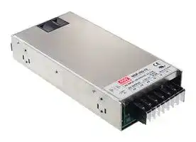
MSP-450-48
AC/DC Enclosed Power Supply (PSU), Medical, 1 Outputs, 456 W, 48 VDC, 9.5 A
⚠️ Reference pricing provided. In case of supply shortages, we will connect you with our trusted procurement partners to ensure your project's continuity.
- Manufacturer: MEAN WELL
- Product type: AC / DC Enclosed Power Supplies
- SVHC: No SVHC (25-Jun-2025)
- Product Range: MSP-450 Series
- No. of Outputs: 1Outputs
- Output Power Max: 456W
- Input Voltage VAC: 85V AC to 264V AC
- Power Supply Output Type: Adjustable, Fixed
- Output Current - Output 1: 9.5A
- Output Current - Output 2: -
- Output Current - Output 3: -
- Output Current - Output 4: -
- Output Voltage - Output 1: 48VDC
- Output Voltage - Output 2: -
- Output Voltage - Output 3: -
- Output Voltage - Output 4: -
- Power Supply Applications: Medical
| Delivery and price | |
|---|---|
| Units per pack | 10 |
| Price | 113.18 € |
| Current stock | 10+ |
| Lead time | 30 days |
Datasheet

**MSP - 450  series**

MEAN WELL 450W Single Output Medical Type **- series** ~~eee~~

## | ■ Features : •Universal AC input / Full range

   - •Built-in active PFC function, PF>0.95

   - •High efficiency up to 89.5%

   - •Withstand 300VAC surge input for 5 seconds

   - •Protections: Short circuit / Overload / Over voltage / Over temperature

   - •Built-in constant current limiting circuit

- •Medical safety approved (MOOP level)

   - •Built-in cooling Fan ON-OFF control

   - •Built-in DC OK signal

   - •Built-in remote ON-OFF control

   - •Stand by 5V@0.3A

   - •Built-in remote sense function

   - •No load power consumption<0.6W (Note.7) •5 years warranty

## **SPECIFICATION**

|**SPECIFICATION**|**SPECIFICATION**|||||||||
|---|---|---|---|---|---|---|---|---|---|
|**MODEL**||**MSP-450-3.3**|**MSP-450-5**|**MSP-450-7.5**|**MSP-450-12**|**MSP-450-15**|**MSP-450-24**|**MSP-450-36**|**MSP-450-48**|
|**OUTPUT**|**DC VOLTAGE**|3.3V|5V|7.5V|12V|15V|24V|36V|48V|
||**RATED CURRENT**|90A|90A|60A|37.5A|30A|18.8A|12.5A|9.5A|
||**CURRENT RANGE**|0 ~ 90A|0 ~ 90A|0 ~ 60A|0 ~ 37.5A|0 ~ 30A|0 ~ 18.8A|0 ~ 12.5A|0 ~ 9.5A|
||**RATED POWER**|297W|450W|450W|450W|450W|451.2W|450W|456W|
||**RIPPLE & NOISE (max.)Note.2**|80mVp-p|80mVp-p|100mVp-p|120mVp-p|150mVp-p|150mVp-p|240mVp-p|240mVp-p|
||**VOLTAGE ADJ. RANGE**|2.8 ~ 3.8V|4.3 ~ 5.8V|6.8 ~ 9V|10.2 ~ 13.8V|13.5 ~ 18V|21.6 ~ 28.8V|28.8 ~ 39.6V|40.8 ~ 55.2V|
||**VOLTAGE TOLERANCENote.3**|±2.0%|±2.0%|±2.0%|±1.0%|±1.0%|±1.0%|±1.0%|±1.0%|
||**LINE REGULATION**|±0.5%|±0.5%|±0.5%|±0.3%|±0.3%|±0.2%|±0.2%|±0.2%|
||**LOAD REGULATION**|±1.0%|±1.0%|±1.0%|±0.5%|±0.5%|±0.5%|±0.5%|±0.5%|
||**SETUP, RISE TIME**|1000ms, 100ms/230VAC          2500ms, 100ms/115VAC at full load||||||||
||**HOLD UP TIME(Typ.)**|16ms/230VAC          16ms/115VAC at full load||||||||
|**INPUT**|**VOLTAGE RANGENote.5**|85 ~ 264VAC          120 ~ 370VDC||||||||
||**FREQUENCY RANGE**|47 ~ 63Hz||||||||
||**POWER FACTOR(Typ.)**|PF>0.95/230VAC          PF>0.99/115VAC at full load||||||||
||**EFFICIENCY(Typ.)**|80%|83%|86.5%|88%|89%|88%|89%|89.5%|
||**AC CURRENT (Typ.)**|5A/115VAC        2.4A/230VAC||||||||
||**INRUSH CURRENT (Typ.)**|35A/115VAC          70A/230VAC||||||||
||**LEAKAGE CURRENT**|Earth leakage current < 300   A/264VAC , Touch leakage current < 100   A/264VAC<br>μ<br>μ||||||||
|**ENVIRONMENT**<br>**SAFETY &**<br>**FUNCTION**<br>**EMC**<br>**(Note 4)**<br>**OTHERS**<br>**PROTECTION**|**OVERLOAD**|105 ~ 135% rated outputpower||||||||
|||Protection type :Constant current limiting, recovers automatically after fault condition is removed||||||||
||**OVER VOLTAGE**|3.96 ~ 4.62V|6 ~ 7V|9.4 ~ 10.9V|14.4 ~ 16.8V|18.8 ~ 21.8V|30 ~ 34.8V|41.4 ~ 48.6V|57.6 ~ 67.2V|
|||Protection type : Shut down o/pvoltage,re-power on to recover||||||||
||**OVER TEMPERATURE**|95<br>5<br>for 5V ; 90<br>5<br>for 3.3V,7.5V,12V,15V ; 85<br>5<br>for 24V,36V,48V(TSW1)detect on heatsink of power transistor<br>℃± ℃<br>℃± ℃<br>℃± ℃||||||||
|||95<br>5<br>for 3.3V,5V,7.5V ; 90<br>5<br>for 12V,15V ; 80<br>5<br>for 24V,36V,48V(TSW2)detect on mainpower output choke<br>℃± ℃<br>℃± ℃<br>℃± ℃||||||||
|||Protection type : Shut down o/p voltage, recovers automatically after temperature goes down||||||||
||**5V STANDBY**|5VSB : 5V@0.3A ; tolerance<br>5%, ripple : 50mVp-p(max.)<br>±||||||||
||**DC OK SIGNAL**|PSU turn on : 3.3 ~ 5.6V ; PSU turn off : 0 ~ 1V||||||||
||**REMOTE CONTROL**|RC+ / RC-: 4 ~ 10V or open = power on ; 0 ~ 0.8V or short = power off||||||||
||**FAN CONTROL (Typ.)**|Load 20<br>10% or RTH2<br>50<br>Fan on<br>±<br>≧<br>℃||||||||
||**WORKING TEMP.**|-40 ~ +70<br>(Refer to "Derating Curve")<br>℃||||||||
||**WORKING HUMIDITY**|20 ~ 90% RH non-condensing||||||||
||**STORAGE TEMP., HUMIDITY**|-40 ~ +85<br>,10 ~ 95% RH<br>℃||||||||
||**TEMP. COEFFICIENT**|±<br>℃<br>℃<br>0.03%/<br>(0 ~ 50<br>)||||||||
||**VIBRATION**|10 ~ 500Hz, 5G 10min./1cycle, 60min. each along X, Y, Z axes||||||||
||**SAFETY STANDARDS**|ANSI/AAMI ES60601-1,IEC60601-1 approved||||||||
||**WITHSTAND VOLTAGE**|I/P-O/P:4KVAC     I/P-FG:2KVAC     O/P-FG:0.5KVAC||||||||
||**ISOLATION RESISTANCE**|I/P-O/P, I/P-FG, O/P-FG:100M Ohms / 500VDC / 25<br>/ 70% RH<br>℃||||||||
||**EMC EMISSION**|Compliance to EN55011 (CISPR11) Class B, EN61000-3-2,-3||||||||
||**EMC IMMUNITY**|Compliance to EN61000-4-2,3,4,5,6,8,11, EN60601-1-2||||||||
||**MTBF**|159.3K hrs min.      MIL-HDBK-217F(25<br>)<br>℃||||||||
||**DIMENSION**|218*105*41mm (L*W*H)||||||||
||**PACKING**|1.19Kg; 12pcs/15.3Kg/0.82CUFT||||||||
|**NOTE**|1. All parameters NOT specially mentioned are measured at 230VAC input, rated load and 25<br>of ambient temperature.<br>℃<br>2. Ripple & noise are measured at 20MHz of bandwidth by using a 12" twisted pair-wire terminated with a 0.1uf & 47uf parallel capacitor.<br>3. Tolerance : includes set up tolerance, line regulation and load regulation.<br>4. The power supply is considered a component which will be installed into a final equipment. The final equipment must be re-confirmed that it still meets<br>EMC directives. For guidance on how to perform these EMC tests, please refer to EMI testing of component power supplies.<br>(as available on http://www.meanwell.com)<br>5. Derating may be needed under low input voltages. Please check the derating curve for more details.<br>6. Length of set up time is measured at first cold start. Turning ON/OFF the power supply may lead to increase of the set up time.<br>7. No load power consumption<0.5W when RC- & RC+ (CN100 pin1,2) 0 ~ 0.8V or short.<br>8. When the input voltage is less than 40VAC, the SPS may exhibit degradation of performance. The final product manufacturers must re-confirm this<br>deviation that does not affect basic safetyor essentialperformance.|||||||||


2. Ripple & noise are measured at 20MHz of bandwidth by using a 12" twisted pair-wire terminated with a 0.1uf & 47uf parallel capacitor.

3. Tolerance : includes set up tolerance, line regulation and load regulation.

4. The power supply is considered a component which will be installed into a final equipment. The final equipment must be re-confirmed that it still meets EMC directives. For guidance on how to perform these EMC tests, please refer to EMI testing of component power supplies. (as available on http://www.meanwell.com)

5. Derating may be needed under low input voltages. Please check the derating curve for more details.

6. Length of set up time is measured at first cold start. Turning ON/OFF the power supply may lead to increase of the set up time.

7. No load power consumption<0.5W when RC- & RC+ (CN100 pin1,2) 0 ~ 0.8V or short.

8. When the input voltage is less than 40VAC, the SPS may exhibit degradation of performance. The final product manufacturers must re-confirm this deviation that does not affect basic safety or essential performance.

_File Name:MSP-450-SPEC   2013-10-21_

**MSP - 450  series**

450W Single Output Medical Type

**==> picture [483 x 314] intentionally omitted <==**

**----- Start of picture text -----**<br>
Mechanical Specification Case No. 995A        Unit:mm<br>152.4 32.8<br>O/P<br>1<br>2<br>Air flow<br>direction FAN 3<br>4<br>I/P 5<br>1 6<br>2<br>3 4-M4 L=5 1 7<br>2 8<br>218<br>152.4 32.8<br>18max.<br>12max.<br>8-M4 L=4 (Both Sides)<br>AC Input Terminal Pin No.   DC Output Terminal Pin No.  Connector Pin No. Assignment(CN100) : HRS DF11-8DP-2DS or equivalent<br>Assignment Assignment Pin No. Assignment Pin No. Assignment Mating Housing Terminal<br>Pin No. Assignment Pin No. Assignment 1 RC+ 5 DC-OK<br>1 AC/L 1~3 -V 2 RC- 6 GND HRS DF11-8DS HRS DF11-**SC<br>2 AC/N 4~6 +V 3 AUX 7 +S or equivalent or equivalent<br>3 FG 4 AUXG 8 -S<br>**----- End of picture text -----**<br>


**==> picture [482 x 320] intentionally omitted <==**

**----- Start of picture text -----**<br>
Block Diagram PMW fosc : 70KHz<br>RECTIFIERS<br>AUX AUX<br>&<br>POWER AUXG<br>FILTER<br>+S<br>EMI  INRUSHACTIVE RECTIFIERS POWER RECTIFIERS +V<br>I/P FILTER CURRENTLIMITING PFC& SWITCHING FILTER& -V<br>-S<br>DETECTION<br>O.T.P. O.L.P. CIRCUIT DC OK<br>FG<br>O.T.P.<br>PFC PWM O.V.P.<br>CONTROL CONTROL<br>REMOTE RC+<br>CONTROL RC-<br>Derating Curve Output Derating VS Input Voltage<br>125 100<br>90<br>100<br>80<br>80<br>70<br>50 60<br>50<br>20 40<br>-40 0 10 20 30 40 50 60 70 (HORIZONTAL) 85 100 125 135 155 264<br>AMBIENT TEMPERATURE ( ℃ ) INPUT VOLTAGE (V) 60Hz<br>**----- End of picture text -----**<br>


_File Name:MSP-450-SPEC   2013-10-21_

**MSP - 450  series**

450W Single Output Medical Type

## **Function Description of CN100**

**==> picture [481 x 613] intentionally omitted <==**

**----- Start of picture text -----**<br>
Pin No. Function Description<br>1 RC+ Turns the output on and off by electrical or dry contact between pin 2 (RC-), Short: Power OFF, Open: Power ON.<br>2 RC- Remote control ground.<br>Auxiliary voltage output, 4.75~5.25V, referenced to pin 4(AUXG). The maximum load current is 0.3A. This output has the built-in oring<br>3 AUX<br>diodes and is not controlled by the "remote ON/OFF control".<br>4 AUXG Auxiliary voltage output ground. The signal return is isolated from the output terminals (+V & -V).<br>5 DC-OK DC-OK Signal is a TTL level signal, referenced to pin6(DC-OK GND). High when PSU turns on.<br>6 GND This pin connects to the negative terminal(-V). Return for DC-OK signal output.<br>Positive sensing. The +S signal should be connected to the positive terminal of the load. The +S and -S leads should be twisted in pair to<br>7 +S<br>minimize noise pick-up effect. The maximum line drop compensation is 0.5V.<br>Negative sensing. The -S signal should be connected to the negative terminal of the load. The -S and +S leads should be twisted in pair to<br>8 -S<br>minimize noise pick-up effect. The maximum line drop compensation is 0.5V.<br>Function Manual<br>1.Remote Sense<br>    The remote sensing compensates voltage drop on<br>    the load wiring up to 0.5V. CN100<br>CN100<br>2 RC- RC+ 1<br>AUXG AUX<br>2 1<br>8 7 GND DC-OK<br>8 7<br>-S +S<br>+ -<br>+S -S<br>(Pin7) LOAD (Pin8)<br>Sense lines should<br>Fig 1. 1 be twisted  in pairs<br>2.DC-OK Signal<br>    DC-OK signal is a TTL level signal. High when PSU turns on.<br>CN100<br>Between DC-OK(pin5) and GND(pin6) Output Status<br>CN100<br>3.3 ~ 5.6V ON 2 RC- RC+ 1<br>0 ~ 1V OFF AUXG AUX<br>2 1<br>8 7 GND DC-OK<br>8 -S +S 7<br>Fig 2. 1<br>3.Remote Control<br>    The PSU can be turned ON/OFF by using the<br>    "Remote Control" function. CN100<br>2 1<br>CN100<br>Between RC+(pin1) and RC-(pin2) Output Status RC- RC+<br>SW ON (Short) OFF AUXG AUX<br>2 1<br>SW OFF (Open) ON 8 7 GND DC-OK<br>8 -S +S 7<br>SW<br>**----- End of picture text -----**<br>


Fig 3. 1

_File Name:MSP-450-SPEC   2013-10-21_
Updated at June 6, 2026
About Novapart
Novapart is a B2B electronic component broker specialising in stock shortages and cost reduction. We source hard-to-find parts and identify compliant alternatives across a catalogue of 410,000+ components from 500+ manufacturers.
Learn more →Stock Shortage Specialist
When a component is unavailable, discontinued or has an unacceptable lead time, we tap into our network of vetted European and Asian distributors to source what you need — without compromising on quality or traceability.
Request a quote →Compliant Alternatives
We identify pin-to-pin, electrically equivalent substitutes that meet the same certifications (RoHS, AEC-Q100, REACH) as your original specification — validated against datasheets, not just part numbers. Often at a lower cost.
BOM Analysis service →