
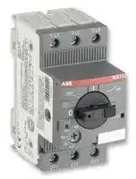


MS132-2.5
MOTOR STARTER,1.6-2.5A
- Manufacturer: ABB
- Product type: Motor Starters
- ABB-MS132-2.5-MOTOR STARTER,1.6-2.5A
- No. of Poles: 3 Pole
- Power Rating: 1.5hp
- No. of Phases: Single Phase, Three Phase
- Product Range: MS132
- Current Rating: 2.5A
- IP / NEMA Rating: IP20
- Motor Starter Type: Manual Starter
- Supply Voltage Max: 690VAC
- Supply Voltage Min: 230VAC
| Delivery and price | |
|---|---|
| Units per pack | 1 |
| Price | 36.5 € |
| Current stock | 10+ |
| Lead time | 30 days |
**Data sheet**

## Manual motor starter MS132

Manual motor starters are electromechanical protection devices for the main circuit. They are used mainly to switch motors manually ON/OFF and protect them fuse less against short-circuit, overload and phase failures. Fuse less protection with a manual motor starter saves costs, space and ensures a quick reaction under short-circuit condition, by switching off the motor within milliseconds. Fuse less starter combinations are setup together with contactors.

Description

- Overload protection – trip class 10

Ordering details MS132 screw terminal

- Phase loss sensitivity

- Disconnect function

- Temperature compensation from -25 … +60 °C

- Adjustable current setting for overload protection

- Suitable for three- and single-phase application

- Trip-free mechanism

- Trip indication

- Clear switch position indication ON/OFF/TRIP

- Lockable handle

|Setting range<br>[A]|Type|Trip<br>class|Order code|Packaging<br>unit [Pcs]|Weight<br>[g]|
|---|---|---|---|---|---|
|0.10  ...  0.16|MS132-0.16|10A|1SAM350000R1001|1|215|
|0.16  ...  0.25|MS132-0.25|10|1SAM350000R1002|1|215|
|0.25  ...  0.40|MS132-0.4|10|1SAM350000R1003|1|215|
|0.40  ...  0.63|MS132-0.63|10|1SAM350000R1004|1|215|
|0.63  ...  1.00|MS132-1.0|10|1SAM350000R1005|1|215|
|1.00  ...  1.60|MS132-1.6|10|1SAM350000R1006|1|265|
|1.60 ...  2.50|MS132-2.5|10|1SAM350000R1007|1|265|
|2.50 ...  4.00|MS132-4.0|10|1SAM350000R1008|1|265|
|4.00  ...  6.30|MS132-6.3|10|1SAM350000R1009|1|265|
|6.30  ... 10.00|MS132-10|10|1SAM350000R1010|1|265|
|10.00  ... 16.00|MS132-16|10|1SAM350000R1011|1|310|
|16.00  ... 20.00|MS132-20|10|1SAM350000R1013|1|310|
|20.00  ... 25.00|MS132-25|10|1SAM350000R1014|1|310|
|25.00  ... 32.00|MS132-32|10|1SAM350000R1015|1|310|
|||||||


Note: MS132 with pre-assembled auxiliary conact HKF1-11, please order as follow 1SAM250005Rxxxx

## Application

The manual motor starters protect the load and the installation against short-circuit and overload. They are three pole protection devices with thermal tripping elements for overload protection and electro-magnetic tripping elements for shortcircuit protection. Furthermore, they provide a disconnect function for safely isolation of the installation and the supply and can be used for the manual switching of loads.

The manual motor starters have a setting scale in Amperes, which allows the direct adjusting of the device without any additional calculation. In compliance with international and national standards, the setting current is the rated current of the motor and not the tripping current (no tripping at 1.05 x I, tripping at 1.2 x I; I = setting current).

## Operation mode

## Single-phase operation

## Three-phase operation

## Connections

**==> picture [313 x 168] intentionally omitted <==**

**----- Start of picture text -----**<br>
Terminals 1L1, 3L2, 5L3<br>oe i ri<br>z<br>ABE 5 15<br>Switch position TRIP<br>Lockable handle<br>Trip indication<br>Test function<br>for short-circuit<br>Current setting range<br>Terminals 2T1, 4T2, 6T3<br>**----- End of picture text -----**<br>


## Resistance and power losses per phase

|||||||
|---|---|---|---|---|---|
|Type|Lower value<br>setting range<br>[A]|Upper value<br>setting range<br>[A]|Resistance<br>per phase<br>[W]|Power loss per Phase [W] at<br>Lower value of<br>Upper value of<br>settingrange<br>settingrange||
|MS132-0.16|0.10|0.16|66.00|0.7|1.7|
|MS132-0.25|0.16|0.25|25.50|0.7|1.7|
|MS132-0.4|0.25|0.40|10.38|0.7|1.7|
|MS132-0.63|0.40|0.63|4.36|0.7|1.7|
|MS132-1.0|0.63|1.00|1.605|0.7|1.7|
|MS132-1.6|1.00|1.60|0.648|0.7|1.7|
|MS132-2.5|1.60|2.50|0.272|0.7|1.7|
|MS132-4.0|2.50|4.00|0.106|0.7|1.7|
|MS132-6.3|4.00|6.30|0.046|0.7|1.7|
|MS132-10|6.30|10.0|0.024|0.9|2.4|
|MS132-16|10.0|16.0|0.011|1.1|2.8|
|MS132-20|16.0|20.0|0.0057|1.5|2.3|
|MS132-25|20.0|25.0|0.0045|1.8|2.8|
|MS132-32|25.0|32.0|0.0030|1.9|3.1|
|||||||


2  2CDC131021D0201

Dimensions

MS132 ≤ 10 A

MS132 > 10 A

**==> picture [258 x 188] intentionally omitted <==**

**----- Start of picture text -----**<br>
81,25 / 3,2"<br>72,4 / 2,85"<br>1,5 / 0,06"  5,5 / 0,22"  43,5 / 1,71"<br>14 / 0,55"  14 / 0,55"<br>45 / 1,77"<br>2CDC242015F0009<br> mm / inch<br>1,7 / 0,1"<br>90 / 3,54"  75 / 2,95"  35 / 1,38" 45 / 1,77"<br>**----- End of picture text -----**<br>


## MS132 ≤ 10 A + screw fixing kit

**==> picture [258 x 200] intentionally omitted <==**

**----- Start of picture text -----**<br>
Ø 4,5 / Ø 0,18"  9 / 0,35" 5,4 / 0,21"<br>17,5 / 0,69"<br>2CDC242017F0009<br> mm / inch<br>122 / 4,8" 110 / 4,33"<br>**----- End of picture text -----**<br>


**==> picture [258 x 188] intentionally omitted <==**

**----- Start of picture text -----**<br>
81,05 / 3,19"<br>72,2 / 2,84"<br>1,5 / 0,06" 5,5 / 0,22" 43,3 / 0,22"<br>14 / 0,55"  14 / 0,55"<br>45 / 1,77"<br>2CDC242016F0009<br> mm / inch<br>1,7 / 0,1"<br>97,8 / 3,85" 75 / 2,95" 35 / 1,38" 45 / 1,77"<br>**----- End of picture text -----**<br>


## MS132 > 10 A + screw fixing kit

**==> picture [258 x 201] intentionally omitted <==**

**----- Start of picture text -----**<br>
Ø 4,5 / Ø 0,18"  9 / 0,35"  5,4 / 0,21"<br>17,5 / 0,69"<br>2CDC242018F0009<br> mm / inch<br>122 / 4,8"  110 / 4,33"<br>**----- End of picture text -----**<br>


## Wiring diagram

**==> picture [123 x 101] intentionally omitted <==**

2CDC131021D0201 3

Data at TA = 40 °C and at rated values, if nothing else indicated

**==> picture [527 x 637] intentionally omitted <==**

**----- Start of picture text -----**<br>
Type  MS132<br>Technical data  Terminals<br>Main circuit  1L1-3L3-5L5<br>2T1-4T2-6T3<br>Rated operational voltage Ue acc. to IEC/EN 60947-1  AC  690 V<br>DC  -<br>Rated operational current I e see separate table<br>Rated current In /  see „Rated Operational Current“<br>Conventional free-air thermal current I th<br>Setting range - thermal overload protection  see ordering data<br>Rated instantaneous short-circuit current setting I i see separate table<br>Rated service short-circuit breaking capacity I cs see separate table<br>Rated ultimate short-circuit breaking capacity I cu see separate table<br>Trip class acc. to IEC/EN 60947-4-1  see ordering data<br>Rated frequency acc. to IEC/EN 60947-1  50 / 60 Hz<br>Number of poles  3<br>Resistence per phase  see separate table<br>Power loss per phase  lower value of setting range  see separate table<br>upper value of setting range  see separate table<br>Isolation data<br>Rated impulse withstand voltage U imp  acc. to IEC/EN 60947-1   6 kV<br>Rated insulation voltage U i   acc. to IEC/EN 60947-1   690 V<br>Pollution degree acc. to IEC/EN 60664  3<br>Electrical connection<br>MS132 ≤ 10A<br>           Connecting capacity solid  1/2 x 1 ... 4 mm [2]<br>flexible with ferrule  1/2 x 0.75 ... 2.5 mm [2]<br>flexible with ferrule isolated 1/2 x 0.75 ... 2.5 mm [2]<br>flexible without ferrule  1/2 x 0.75 ... 2.5 mm [2]<br>           Stripping length  9 mm<br>           Tightening torque  0.8 ... 1.2 Nm<br>           Connection screw  M3.5 (Pozidrive 2)<br>MS132-16<br>           Connecting capacity solid  1/2 x 1 ... 4 mm [2]<br>flexible with ferrule  1/2 x 0.75 ... 2.5 mm [2]<br>flexible with ferrule isolated 1/2 x 0.75 ... 2.5 mm [2]<br>flexible without ferrule  1/2 x 0.75 ... 2.5 mm [2]<br>           Stripping length  10 mm<br>           Tightening torque  1.5 Nm<br>           Connection screw  M4 (Pozidrive 2)<br>MS132-20, -25, -32<br>           Connecting capacity solid  1/2 x 2.5 ... 6 mm [2]<br>flexible with ferrule  1/2 x 1 ... 6 mm [2]<br>flexible with ferrule isolated 1/2 x 1 ... 6 mm [2]<br>flexible without ferrule  1/2 x 2.5 ... 6 mm [2]<br>           Stripping length  10 mm<br>           Tightening torque  2 Nm<br>           Connection screw  M4 (Pozidrive 2)<br>**----- End of picture text -----**<br>


4  2CDC131021D0201

**==> picture [528 x 674] intentionally omitted <==**

**----- Start of picture text -----**<br>
Type  MS132<br>General Data<br>Mechniacl durability 10 [5]<br>Electrical durability 5 x 10 [4]<br>Duty time  100%<br>Dimensions (W x H x D) see dimension drawing<br>Weight  see ordering data<br>Mounting DIN-rail (EN 60715)<br>Mounting positions  optional for single mounting<br>(position 1-6)<br>Group Mounting on request<br>Minimum distance to other units same type  horizontal  none<br>vertical  150 mm<br>Minimum distance to electrical conductive wall (earthed)  horizontal  none<br>vertical  75 mm<br>Degree of protection acc. to IEC/EN 60947-1  enclosure / terminals  IP20<br>Utilization Category acc. to IEC/EN 60947-2  A<br>Altitude  up to 2000 m<br>Environmental data<br>Ambient air temperature range<br>  Operation  open - compensated  -25 °C ... +60 °C<br>open  -25 °C ... +60 °C<br>  Storage  -50 °C ... +80 °C<br>Temperature compensation  continuous<br>Vibration (sinusoidal) acc. to IEC/EN 60068-2-6 (Fc) 5 g / 3 - 150 Hz<br>Shock (half-sine) acc. to IEC/EN 60068-2-27 (Ea) 25 g / 11 ms<br>Standards / Directives<br>Standard  IEC/EN 60947–2, ICE/EN 60947-4-1,<br>IEC/EN 60947-1, UL 508;<br>CSA 22.2 No. 14<br>Low Voltage Directive  2006/95/EC<br>EMC Directive  2004/108/EC<br>RoHS Directive  2002/95/EC<br>Electromagnetic compatibility<br>not applicable<br>Approvals, markings<br>Approvals  see last page<br>Markings  see last page<br>UL/CSA<br>Max. operational voltage   600 V<br>General purpose rating at max. 600 VAC  see separate table<br>Motor ratings<br>  Horse power  see separate table<br>  Full load amps (FLA) see separate table<br>  Locked rotor amps (LRA) see separate table<br>Short circuit rating RMS at 480 VAC  30 kA<br>Short circuit rating RMS at 600 VAC  18 kA<br>Short-Circuit Protective devices  see separate table<br>**----- End of picture text -----**<br>


2CDC131021D0201 5

**==> picture [527 x 300] intentionally omitted <==**

**----- Start of picture text -----**<br>
Type  MS132<br>Technical data<br>Electrical connection<br>MS132 ≤ 10A<br>          Connecting capacity solid   1/2 x AWG16 ... AWG12<br>stranded  1/2 x AWG16 ... AWG12<br>flexible without ferrule  1/2 x AWG16 ... AWG12<br>           Stripping length  9 mm<br>           Tightening torque  10 - 12 lb-in<br>           Connection screw  M3.5 (Pozidrive 2)<br>MS132-16<br>           Connecting capacity solid   1/2 x AWG16 ... AWG12<br>stranded  1/2 x AWG16 ... AWG12<br>flexible without ferrule  1/2 x AWG16 ... AWG12<br>           Stripping length  10 mm<br>           Tightening torque  14 lb-in<br>           Connection screw  M4 (Pozidrive 2 / 6.5 mm)<br>MS132-20, -25, -32<br>           Connecting capacity stranded  1/2 x AWG12 ... AWG8<br>flexible without ferrule  1/2 x AWG12 ... AWG8<br>           Stripping length  10 mm<br>           Tightening torque  18 lb-In<br>           Connection screw  M4 (Pozidrive 2)<br>**----- End of picture text -----**<br>


**==> picture [348 x 213] intentionally omitted <==**

**----- Start of picture text -----**<br>
Type  Rated instantaneous  Rated current ln / Conventional<br>short-circuit current setting li [A]  free-air thermal current lth [A]<br>MS132-0.16   1.25 … 1.87  0.16<br>MS132-0.25   1.95 … 2.92  0.25<br>MS132-0.4   3.12 … 4.68  0.40<br>MS132-0.63   4.91 … 7.37  0.63<br>MS132-1.0   9.20 … 13.8  1.00<br>MS132-1.6   14.7 … 22.1  1.60<br>MS132-2.5   23.0 … 34.5  2.50<br>MS132-4.0   40.0 … 60.0  4.00<br>MS132-6.3   63.0 … 94.5  6.30<br>MS132-10   120 … 180  10.0<br>MS132-16   192 … 288  16.0<br>MS132-20   240 … 360  20.0<br>MS132-25   300 … 450  25.0<br>MS132-32   384 … 576  32.0<br>**----- End of picture text -----**<br>


## Short-Circuit protection

**==> picture [348 x 213] intentionally omitted <==**

**----- Start of picture text -----**<br>
Type  400 V AC  690 V AC<br>ICS [kA]  ICU [kA]  gG [A]  ICS [kA]  ICU [kA]  gG [A]<br>MS132-0.16  100  100  °  100  100  °<br>MS132-0.25  100  100  °  100  100  °<br>MS132-0.4  100  100  °  100  100  °<br>MS132-0.63  100  100  °  100  100  °<br>MS132-1.0  100  100  °  100  100  °<br>MS132-1.6  100  100  °  100  100  °<br>MS132-2.5  100  100  °  100  100  °<br>MS132-4.0  100  100  °  3  3  on request<br>MS132-6.3  100  100  °  3  3  on request<br>MS132-10  100  100  °  3  3  on request<br>MS132-16  50  50  on request 3  3  on request<br>MS132-20  50  50  on request 3  3  on request<br>MS132-25  50  50  on request 3  3  on request<br>MS132-32  25  25  on request 3  3  on request<br>**----- End of picture text -----**<br>


lCS = Rated service short-circuit breaking capacity

lCU = Rated ultimate short-circuit breaking capacity

o  = No back-up fuse required, because short-circut proof up to 100 kA

6  2CDC131021D0201

UL / CSA ratings

**==> picture [527 x 226] intentionally omitted <==**

**----- Start of picture text -----**<br>
Type  Motor rating, single phase<br>120 VAC  240 VAC  480 VAC<br>hp FLA  LRA  hp FLA  LRA  hp FLA  LRA<br>MS132-0.16  -  0.16  0.96  -   0.16  0.96  -   0.16  0.96<br>MS132-0.25  -  0.25  1.5  -  0.25  1.5  -  0.25  1.5<br>MS132-0.4  -  0.4  2.4  -  0.4  2.4  -  0.4  2.4<br>MS132-0.63  -  0.63  3.78  -  0.63  3.78  -  0.63  3.78<br>MS132-1.0  -  1  6  -  1  6  -  1  6<br>MS132-1.6  -  1.6  9.6  1/10  1.6  9.6  -  1.6  9.6<br>MS132-2.5  -  2.5  15  1/6  2.5  15  1/2  2.5  15<br>MS132-4.0  1/8  4  24  1/3  4  24  1/2  4  24<br>MS132-6.3  1/4  6.3  37.8  1/2  6.3  37.8  1  6.3  37.8<br>MS132-10  1/2  9.8  58.8  1-1/2  10  60  3  -  -<br>MS132-16  1  16  96  2  12  72  5  -  -<br>MS132-20  1-1/2  20  120  3  -  -  5  -  -<br>MS132-25  2  24  144  3  -  -  7-1/2  -  -<br>MS132-32  2  24  144  5  -  -  10  -  -<br>**----- End of picture text -----**<br>


**==> picture [527 x 225] intentionally omitted <==**

**----- Start of picture text -----**<br>
Type  Motor rating, three phase<br>120 VAC   240 VAC   480 VAC   600 VAC<br>hp FLA  LRA  hp FLA  LRA  hp FLA  LRA  hp FLA  LRA<br>MS132-0.16  -   0.16  0.96  -   0.16  0.96  -   0.16  0.96  -   0.16  0.96<br>MS132-0.25  -  0.25  1.5  -  0.25  1.5  -  0.25  1.5  -  0.25  1.5<br>MS132-0.4  -  0.4  2.4  -  0.4  2.4  -  0.4  2.4  -  0.4  2.4<br>MS132-0.63  -  0.63  3.78  -  0.63  3.78  -  0.63  3.78  -  0.63  3.78<br>MS132-1.0  -  1  6  -  1  6  -  1  6  1/2  1  6<br>MS132-1.6  -  1.6  9.6  -  1.6  9.6  3/4  1.6  9.6  3/4  1.6  9.6<br>MS132-2.5  -  2.5  15  1/2  2.5  15  1  2.5  15  1-1/2  2.5  15<br>MS132-4.0  -  4  24  1  4  24  2  4  24  3  -  -<br>MS132-6.3  1/2  6.3  37.8  1-1/2  6.3  37.8  3  -  -  5  -  -<br>MS132-10  3/4  10  60  3  -  -  5  -  -  7-1/2  -  -<br>MS132-16  2  16  84  5  -  -  10  -  -  10  -  -<br>MS132-20  3  -  -  5  -  -  10  -  -  15  -  -<br>MS132-25  3  -  -  7-1/2  -  -  15  -  -  20  -  -<br>MS132-32  5  -  -  10  -  -  20  -  -  25  -  -<br>**----- End of picture text -----**<br>


**==> picture [303 x 226] intentionally omitted <==**

**----- Start of picture text -----**<br>
Type  General purpose   Protective devices<br>rating at max.   Fuse K5 / RK5  Circuit breaker<br>600 VAC [A] [A] [A]<br>MS132-0.16  0.16  250   250<br>MS132-0.25  0.25  250   250<br>MS132-0.4  0.40  250   250<br>MS132-0.63  0.63  250   250<br>MS132-1.0  1.00  250   250<br>MS132-1.6  1.60  250   250<br>MS132-2.5  2.50  250   250<br>MS132-4.0  4.00  250   250<br>MS132-6.3  6.30  250   250<br>MS132-10  10.0  250   250<br>MS132-16  16.0  250   250<br>MS132-20  20.0  250   250<br>MS132-25  25.0  250   250<br>MS132-32  32.0  250   250<br>**----- End of picture text -----**<br>


2CDC131021D0201 7

Contact us

ABB STOTZ-KONTAKT GmbH P. O. Box 10 16 80 69006 Heidelberg, Germany Phone: +49 (0) 6221 7 01-0 Fax: +49 (0) 6221 7 01-13 25 E-Mail: info.desto@de.abb.com

You can find the address of your local sales organisation on the ABB home page http://www.abb.com/contacts -> Low Voltage products

Approvals LISTED cULus UL 508 CG 0G GOST-F GOST-R

## CB Scheme

Markings

CE

## Note:

We reserve the right to make technical changes or modify the contents of this document without prior notice. With regard to purchase orders, the agreed particulars shall prevail. ABB AG does not accept any responsibility whatsoever for potential errors or possible lack of information in this document.

We reserve all rights in this document and in the subject matter and illustrations contained therein. Any reproduction, disclosure to third parties or utilization of its contents – in whole or in parts – is forbidden without prior written consent of ABB AG.

Copyright© 2009 ABB All rights reserved
Updated at March 17, 2026
ABB is a global leader in power and automation technologies, recognized for delivering innovative solutions that improve performance while minimizing environmental impact. Serving a diverse range of sectors including industrial processing, OEM, and building services, ABB provides highly reliable components designed to meet the rigorous demands of modern electrical systems. The company is particularly renowned for its advanced circuit protection solutions. This includes a comprehensive selection of thermal magnetic circuit breakers, alongside specialized RCBO, RCD, GFCI, and AFDD circuit breakers. These foundational safety components are supported by a wide array of high-quality fuse holders and circuit breaker accessories, ensuring complete protection for complex industrial and commercial installations. Beyond circuit protection, ABB excels in automation and process control. Their offering features sophisticated visual signal indicator units, industrial switch accessories, and panel instrumentation designed for intuitive system monitoring. Additionally, ABB manufactures a robust range of power relays, safety relays, and AC/DC converters, providing engineers with the critical building blocks needed for efficient, secure, and reliable control panels.
About Novapart
Novapart is a B2B electronic component broker specialising in stock shortages and cost reduction. We source hard-to-find parts and identify compliant alternatives across a catalogue of 410,000+ components from 500+ manufacturers.
Learn more →Stock Shortage Specialist
When a component is unavailable, discontinued or has an unacceptable lead time, we tap into our network of vetted European and Asian distributors to source what you need — without compromising on quality or traceability.
Request a quote →Compliant Alternatives
We identify pin-to-pin, electrically equivalent substitutes that meet the same certifications (RoHS, AEC-Q100, REACH) as your original specification — validated against datasheets, not just part numbers. Often at a lower cost.
BOM Analysis service →