
Image not available
Illustrative purposes only


MS-1001-01A
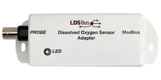
Modbus Adapter, BRIDGETEK Dissolved Oxygen Sensor
⚠️ Reference pricing provided. In case of supply shortages, we will connect you with our trusted procurement partners to ensure your project's continuity.
- Manufacturer: BRIDGETEK
- Product type:
- SVHC: No SVHC (25-Jun-2025)
- For Use With: BRIDGETEK Dissolved Oxygen Sensor
- Accessory Type: Modbus Adapter
| Delivery and price | |
|---|---|
| Units per pack | 1 |
| Price | 112.45 € |
| Current stock | 10+ |
| Lead time | 30 days |
Datasheet

**Modbus DO Sensor Adapter Datasheet Version 1.0**

Document Reference No.: BRT_000490    Clearance No.: BRT#254

## **Modbus DO Sensor Adapter**

## **Datasheet**

## **1 Introduction**

## **1.1 Features**

The Modbus **D** issolved **O** xygen **(DO)** Sensor Adapter is designed to work with an analog galvanic probe to form a complete DO sensor. A BNC connector is built into the adapter for attaching such a probe.

The adapter and probe are calibrated using a single-point calibration procedure and the resulting sensor supports DO measurements ranging from 0 to 20 mg/L with a resolution of 0.01mg/L.

- DO Sensor Adapter integrates directly with Analog Galvanic Dissolved Oxygen probe via BNC connector

- DO measurement range of 0 to 20 mg/L with linearized output and 0.01mg/L resolution

- Single point step-by-step guided calibration

- Implements Modbus protocol

- High report rate of 1 report every 5 seconds

The sensor is suitable for use in water quality measurement applications such as nutrient tanks, fisheries and hatcheries, water treatment and sewage treatment plants, swimming pools, aquariums, and many other applications. Monitoring, alerting, and controlling the system can be done in real-time.

- Low power consumption 88mW (5V)

- Operating temperature range: 0[o] C to +70[o]

- Flush mount and DIN Rail Mount options

Neither the whole nor any part of the information contained in, or the product described in this manual, may be adapted, or reproduced in any material or electronic form without the prior written consent of the copyright holder. This product and its documentation are supplied on an as-is basis and no warranty as to their suitability for any particular purpose is either made or implied. Bridgetek Pte Ltd will not accept any claim for damages howsoever arising as a result of use or failure of this product. Your statutory rights are not affected. This product or any variant of it is not intended for use in any medical appliance, device, or system in which the failure of the product might reasonably be expected to result in personal injury. This document provides preliminary information that may be subject to change without notice. No freedom to use patents or other intellectual property rights is implied by the publication of this document. Bridgetek Pte Ltd, 1 Tai Seng Avenue, Tower A, #03-05, Singapore 536464. Singapore Registered Company Number: 201542387H

Copyright © Bridgetek Pte Ltd

1

**Modbus DO Sensor Adapter Datasheet Version 1.0**

Document Reference No.: BRT_000490    Clearance No.: BRT#254

## **2 Part Numbers / Ordering Information**

|**Part Number**|**Description**|
|---|---|
|MS-1001-01A|Modbus Dissolved Oxygen(DO)Sensor Adapter|
|MA-0102-01A|Modbus RS485-RJ11 Cable(30cm)|
|LA-1201-01A|LDSBus DIN Rail Mount Set|


**Table 1 - Part Numbers / Ordering Information**

Copyright © Bridgetek Pte Ltd

2

**Modbus DO Sensor Adapter Datasheet Version 1.0**

Document Reference No.: BRT_000490    Clearance No.: BRT#254

**==> picture [451 x 612] intentionally omitted <==**

**----- Start of picture text -----**<br>
|||
|---|---|
|Table of Contents|
|1|Introduction .............................................................. 1|
|1.1|Features .............................................................................. 1|
|2|Part Numbers / Ordering Information ....................... 2|
|3|Specifications ............................................................ 4|
|4|FCC Compliance Statement ........................................ 5|
|5|Hardware Features .................................................... 6|
|6|Sensor Adapter Configuration and Installation .......... 8|
|6.1|Connection Diagram for Standard Modbus Power Supply .... 8|
|6.2|RS485-RJ11 Cable(30cm) ................................................... 9|
|7|Mounting Instructions ............................................. 10|
|7.1|Flush Mount ....................................................................... 10|
|7.2|DIN Rail Mount .................................................................. 10|
|8|Modbus Registers .................................................... 11|
|9|Mechanical Dimensions ........................................... 12|
|10|System Status LED Indicators.................................. 13|
|11|Probe Selection ....................................................... 14|
|12|Contact Information ................................................ 15|
|Appendix A – References ............................................. 16|
|Document References ............................................................... 16|
|Acronyms and Abbreviations ..................................................... 16|
|Appendix B – List of Figures and Tables ....................... 17|
|List of Figures ........................................................................... 17|
|List of Tables ............................................................................. 17|
|Appendix C – Revision History ..................................... 18|

**----- End of picture text -----**<br>


Copyright © Bridgetek Pte Ltd

3

**Modbus DO Sensor Adapter Datasheet Version 1.0**

Document Reference No.: BRT_000490    Clearance No.: BRT#254

## **3 Specifications**

|**Features**<br>~~oo~~|Interface|BNC – DO probe connector<br>RS485 Modbus RTU|
|---|---|---|
||LED Indicator (RGB)|System Status Indicator (Please refer toLED<br>section)|
||Mounting<br>|Flush Mount|
|||DIN Rail Mount<br>~~PC~~<br>|
|**Power**<br>~~oo~~<br>~~SSS~~|Modbus Voltage<br>|9-24V DC Bus Power<br>~~PC~~<br>|
||Device Input Voltage<br>~~Pe~~|5V DC Bus Power<br>~~PC~~<br>~~Pe~~|
||Typical Power<br><br>~~ns~~|5V,88mW<br>~~PC~~<br><br>~~ns~~|
||Max. Power<br><br>~~a~~<br>~~SSS~~|223mW<br>~~PC~~<br><br>~~SSS~~|
|**DO Sensor input**<br>**module**<br>~~oo~~<br>~~SSS~~<br>~~SS~~|Detection Range<br><br>~~SSS~~|0– 20 mg/L<br>~~PC~~<br><br>~~SSS~~|
||Resolution<br>~~SSS~~<br>~~es~~|0.01mg/L<br>~~SSS~~<br>~~es~~|
||Response Time<br>~~SSS~~<br>~~nD~~|<1Minute<br>~~SSS~~<br>~~nD~~|
||Calibration<br>~~SSS~~<br>~~se~~<br>~~SS~~|1 Point Calibration<br>~~SSS~~<br>~~se~~|
|**Physical**<br>**Characteristics**<br>~~SSS~~<br>~~SS~~|Color<br>~~SSS~~<br>~~SS~~|White<br>~~SSS~~|
||Housing<br>~~SS~~<br>~~es~~|Polycarbonate<br>~~es~~|
||Dimensions<br>~~SS~~<br>~~nD~~|L117.6mm x W42.9mm x H29.7mm<br>~~nD~~|
|**Environmental**<br>**Limits**<br>~~SS~~<br>~~SS~~<br>~~—_—__—————EE~~|OperatingTemperature<br>~~SS~~<br>~~SS~~|0 to 70°C<br>~~SS~~|
||Storage Temperature<br>~~SS~~<br>~~ns~~|-20 to 85°C<br>~~SS~~<br>~~ns~~|
||Ambient Relative<br>Humidity<br>~~SS~~<br>~~—_—__—————EE~~|5 to 95% (non-condensing)<br>~~SS~~<br>~~—_—__—————EE~~|
|**Package**<br>**Contents**<br>~~—_—__—————EE~~<br>~~Pe~~|Device<br>~~—_—__—————EE~~|1x Modbus Dissolved Oxygen Sensor Adapter<br>~~—_—__—————EE~~|
||Wire Assembly<br>~~—_—__—————EE~~<br>~~es~~<br>~~eee~~|1x Modbus RS485-RJ11 Cable(30cm)<br>~~—_—__—————EE~~<br>~~es~~<br>~~eee~~|
|**Optional**<br>~~—_—__—————EE~~<br>~~Pe~~|MountingAccessories<br>~~—_—__—————EE~~<br>~~es~~<br>~~eee~~|1x LDSBus DIN Rail Mount set<br>~~—_—__—————EE~~<br>~~es~~<br>~~eee~~|


Copyright © Bridgetek Pte Ltd

4

**Modbus DO Sensor Adapter Datasheet Version 1.0**

Document Reference No.: BRT_000490    Clearance No.: BRT#254

## **4 FCC Compliance Statement**

This device complies with part 15 of the FCC Rules. Operation is subject to the following two conditions:

(1) These devices may not cause harmful interference, and

(2) These devices must accept any interference received, including interference that may cause undesired operation.

**NOTE:** The equipment has been tested and found to comply with the limits for a Class B digital device, pursuant to part 15 of the FCC Rules. These limits are designed to provide reasonable protection against harmful interference in a residential installation. This equipment generates, uses, and can radiate radio frequency energy and, if not installed and used in accordance with the instructions, may cause harmful interference to radio communications. However, there is no guarantee that interference will not occur in a particular installation. If the equipment does cause harmful interference to radio or television reception, which can be determined by turning the equipment off and on, the user is encouraged to try to correct the interference by one or more of the following measures:

- Re-orient or relocate the receiving antenna.

- Increase the separation between the equipment and receiver.

- Connect the equipment into an outlet on a circuit different from that to which the receiver is connected.

-

- Consult the dealer or an experienced radio/TV technician for help.

To maintain compliance with FCC’s RF exposure guidelines, at least 20cm of separation distance between the device and the user's body must be always maintained.

## **FCC Radiation Exposure Statement**

This device complies with FCC radiation exposure limits set forth for an uncontrolled environment and it also complies with Part 15 of the FCC RF Rules. This equipment must be installed and operated in accordance with the instructions provided and the antenna(s) used for this transmitter must be installed to provide a separation distance of at least 20 cm from all persons and must not be colocated or operating in conjunction with any other antenna or transmitter. End-users and installers must be provided with antenna installation instructions and consider removing the no-collocation statement.

## **Caution**

Any changes or modifications not expressly approved by the party responsible for compliance could void the user’s authority to operate the equipment.

Copyright © Bridgetek Pte Ltd

5

**Modbus DO Sensor Adapter Datasheet Version 1.0** Document Reference No.: BRT_000490    Clearance No.: BRT#254

## **5 Hardware Features**

**==> picture [409 x 526] intentionally omitted <==**

**----- Start of picture text -----**<br>
DO Electrode Probe<br>System Status<br>BNC<br>LED Indicator<br>Connector<br>RJ12 Port<br>Flush Mount Slot<br>DIN Rail Mount<br>**----- End of picture text -----**<br>


**Figure 1 - Modbus Dissolved Oxygen Sensor Adapter Hardware Features**

Copyright © Bridgetek Pte Ltd

6

**Modbus DO Sensor Adapter Datasheet Version 1.0**

Document Reference No.: BRT_000490    Clearance No.: BRT#254

|**Function**|**Labels**|**Description**|
|---|---|---|
|BNC Connector|Probe|Probe Interface|
|System Status LED<br>Indicator|LED|Modbus status LED|
|RJ12 Port|Modbus|Modbus data and power interface port. The physical<br>port is RJ12. The connection interface can be<br>RJ11/RJ12.|


**Table 3 - Modbus DO Sensor Adapter Hardware Features**

Copyright © Bridgetek Pte Ltd

7

**Modbus DO Sensor Adapter Datasheet Version 1.0**

Document Reference No.: BRT_000490    Clearance No.: BRT#254

## **6 Sensor Adapter Configuration and Installation**

Please visit https://brtsys.com/resources/software/utility-tools to access the Modbus Configuration Utility guide on how to configure the device name, device address and termination settings before using it for your specific application.

## **6.1 Connection Diagram for Standard Modbus Power Supply**

**==> picture [218 x 65] intentionally omitted <==**

**----- Start of picture text -----**<br>
Modbus Host<br>Controller<br>DoSeo<br>a a<br>**----- End of picture text -----**<br>


**Figure 2 - Connection Diagram for Standard Modbus Power Supply**

## **Setup Instructions:**

1. Use a Cat5e/Cat6e RJ45 Twisted Pair Cable to connect the Modbus controller (Host) to the network for RS485 communication and power.

2. Connect each Modbus device to the network using either an RS485-JST cable or an RS485-RJ11 cable, as provided with the device.

3. Modbus devices have built-in bus termination resistors. These resistors can be enabled or disabled by using the Modbus Configuration Utility. When installing the device as the last device on the bus, these terminations may be used to terminate the bus.

Copyright © Bridgetek Pte Ltd

8

**Modbus DO Sensor Adapter Datasheet Version 1.0**

Document Reference No.: BRT_000490    Clearance No.: BRT#254

## **6.2 RS485-RJ11 Cable(30cm)**

## **Figure 3 - RS485-RJ11 Cable(30cm)**

|**PIN Legend**|**Function**|
|---|---|
|VIN|Modbus Input Voltage 9-24VDC|
|GND|Ground|
|GND|Ground|
|B|RS485-B|
|A|RS485-A|


**Table 4 - RS485-RJ11 Cable(30cm) Pin Configuration**

Copyright © Bridgetek Pte Ltd

9

**Modbus DO Sensor Adapter Datasheet Version 1.0** Document Reference No.: BRT_000490    Clearance No.: BRT#254

## **7 Mounting Instructions**

## **7.1 Flush Mount**

The Modbus DO Sensor Adapter can be flush mounted directly on a wall or any flat surface using 2 M3.5*16mm (thread) screws.

**==> picture [62 x 9] intentionally omitted <==**

**----- Start of picture text -----**<br>
2xM3.5*16mm<br>**----- End of picture text -----**<br>


**Figure 4 - Modbus Dissolved Oxygen Sensor Adapter Flush Mount**

## **7.2 DIN Rail Mount**

The DIN Rail Mount can be fixed using a DIN Rail bracket that has two mounting holes. The package includes mounting screws and a backplate. (The DIN Rail Bracket is not included in the package).

**==> picture [67 x 9] intentionally omitted <==**

**----- Start of picture text -----**<br>
DIN Rail Mount<br>**----- End of picture text -----**<br>


**Figure 5 - Modbus Dissolved Oxygen Sensor Adapter DIN Rail Mount**

Copyright © Bridgetek Pte Ltd

10

**Modbus DO Sensor Adapter Datasheet Version 1.0**

Document Reference No.: BRT_000490    Clearance No.: BRT#254

## **8 Modbus Registers**

|**Parameter**<br>~~Po~~|**Starting**<br>**Address**|**Quantity**<br>**of**<br>**Registers**|**Supported**<br>**Function**<br>**Code**|**Parameter Range and**<br>**Description**|**Default**|
|---|---|---|---|---|---|
|**Address(1)**<br>~~Po~~|0000H|1|0x03/0x10|1 to 126|126|
|**RS485**<br>**Termination(1)**<br>~~Po~~|0001H|1|0x03/0x10|0 - Termination OFF<br>1-Termination ON|Termination<br>OFF|
|**Baud Rate(1)**|0002H|1|0x03/0x10|0 - 1200 bps<br>1 - 2400 bps<br>2 - 4800 bps<br>3 - 9600 bps<br>4 -19200 bps<br>5 - 38400 bps<br>6-115200 bps|9600 bps|
|**Parity(1)**|0003H|1|0x03/0x10|0 – None<br>1 – Odd<br>2-Even|Even|
|**Status LED**<br>**Enable(1)**|0004H|1|0x03/0x10|0 - LED OFF<br>1-LED ON|LED ON|
|**Environment**<br>**Temperature**|0005H|1|0x03/0x10|Environment temperature 0 to<br>40°C|N/A|
|**Sensor**<br>**Calibration**<br>**Version**|0006H|1|0x03/0x10|0x0090 – if calibrated, 0xFFFF<br>no calibration available|0xFFFF|
|**Sensor**<br>**Calibrated**<br>**Date**|0007H|2|0x03/0x10|Calibration date YYYYMMDD<br>0x20221203|N/A|
|**Sensor**<br>**Calibrated**<br>**Constant**|0009H|1|0x03/0x10|Constant value = 0x0004|0x0004|
|**Sensor**<br>**Calibrated**<br>**Voltage**|000AH|1|0x03/0x10|In millivolt (mV)|N/A|
|**Sensor**<br>**Calibrated**<br>**Temperature**|000BH|2|0x03/0x10|Temperature|N/A|
|**Cal XOR**<br>**Checksum**<br>**Value**|000DH|1|0x03/0x10|XOR Checksum from registers<br>06H to 0CH|N/A|
|**Device UUID**|0026H|8|0x03|MSxxxxxxxxxxxxyy where x is<br>ASCII<br>character and yy is 16-bit<br>running number|N/A|
|**Device**<br>**Firmware**<br>**Version**|002EH|1|0x03|0xXXMN<br>XX – Not concerned<br>M – Major<br>N-Minor|N/A|
|**Device Part**<br>**Number**|002FH|1|0x03|Device ID|0x800C|
|**Reserved**<br>~~Po~~|0030H<br>~~Po~~|N/A<br>~~Po~~|N/A<br>~~Po~~|Reserved<br>~~Po~~|N/A<br>~~Po~~|
|**DO**<br>~~sO~~|0031H<br>~~sO~~|1<br>~~sO~~|0x03<br>~~sO~~|0-20000 (0-20 mg/L)<br>~~sO~~|N/A<br>~~sO~~|
|**Sensor ADC**<br>**data**|0032H|1|0x03|0-1023|N/A|
|**Reset**<br>~~a ~~<br>~~es~~|0150H<br> ~~OO~~<br>~~GO~~|1<br>~~OO~~<br>~~GO~~|0x06<br>~~OO~~<br>~~GO~~|Write 1 to reset<br>~~OO~~<br>~~GO~~|N/A<br>~~OO~~<br>~~GO~~<br>~~(~~|
|**Reserved**<br>~~es~~|0151H<br>~~GO~~|N/A<br>~~GO~~|N/A<br>~~GO~~|Reserved<br>~~GO~~|N/A<br>~~GO~~<br>~~(~~|
|**Identify**<br>~~es~~|0152H<br>~~GO~~|1<br>~~GO~~|0x06<br>~~GO~~|Write 1 to start blinking the<br>device @1Hz for 10 seconds<br>~~GO~~|N/A<br>~~GO~~<br>~~(~~|


## **Table 5 - Modbus Registers**

> **(1)** This indicates that any updates to these communication/status register(s) will only take effect after the device has been rebooted.

Copyright © Bridgetek Pte Ltd

11

**Modbus DO Sensor Adapter Datasheet Version 1.0**

Document Reference No.: BRT_000490    Clearance No.: BRT#254

## **9 Mechanical Dimensions**

**Figure 6 - Modbus Dissolved Oxygen Sensor Adapter Dimension – Top View**

**==> picture [19 x 6] intentionally omitted <==**

**----- Start of picture text -----**<br>
29.7<br>**----- End of picture text -----**<br>


**==> picture [388 x 10] intentionally omitted <==**

**----- Start of picture text -----**<br>
Figure 7 - Modbus Dissolved Oxygen Sensor Adapter Dimension – Side View<br>**----- End of picture text -----**<br>


**Figure 8 - Modbus Dissolved Oxygen Sensor Adapter Dimension – Bottom View**

**Note:** All dimensions are in millimetres.

Copyright © Bridgetek Pte Ltd

12

**Modbus DO Sensor Adapter Datasheet Version 1.0**

Document Reference No.: BRT_000490    Clearance No.: BRT#254

## **10 System Status LED Indicators**

|~~ee~~|~~ns~~|~~ns~~|||
|---|---|---|---|---|
|**Device Status**<br>~~ee~~|**LED Color**<br>~~ns~~||**Flashing Frequency**|**Description**|
|Termination ON<br>~~ee~~|BLUE<br>~~ns~~|~~ns~~|Steady – Non-flashing||
|Termination OFF|GREEN||Steady – Non-flashing||
|Device<br>Configuration Error|RED||Steady – Non-flashing|Device configuration<br>error|
|Communication|RED/GREEN/<br>BLUE/YELLOW|**-**|Blink twice (Short blink)|Device in<br>communication|
|Firmware update|YELLOW||Steady – Non-flashing|Device firmware<br>update.|


**Table 6 - System Status LED Indicators**

## **Note:**

1. For reliable communication, ensure that the power supply and the RS485 termination settings are correct.

2. Ensure that the Modbus address and baud rate are configured correctly before deployment.

Copyright © Bridgetek Pte Ltd

13

**Modbus DO Sensor Adapter Datasheet Version 1.0** Document Reference No.: BRT_000490    Clearance No.: BRT#254

## **11 Probe Selection**

The following specifications are recommended for selecting Dissolved Oxygen Probe -

Type : Galvanic Probe Detection Range : 0-50mg/L Connector : BNC

Copyright © Bridgetek Pte Ltd

14

**Modbus DO Sensor Adapter Datasheet Version 1.0**

Document Reference No.: BRT_000490    Clearance No.: BRT#254

## **12 Contact Information**

Refer to https://brtchip.com/contact-us/ for contact information.

## **Distributor and Sales Representatives**

Please visit the Distribution Network – IC & Module (brtchip.com) page for the contact details of our distributor(s) and sales representative(s) in your country.

System and equipment manufacturers and designers are responsible to ensure that their systems, and any Bridgetek Pte Ltd (BRTChip) devices incorporated in their systems, meet all applicable safety, regulatory and system-level performance requirements. All application-related information in this document (including application descriptions, suggested Bridgetek devices and other materials) is provided for reference only. While Bridgetek has taken care to assure it is accurate, this information is subject to customer confirmation, and Bridgetek disclaims all liability for system designs and for any applications assistance provided by Bridgetek. Use of Bridgetek devices in life support and/or safety applications is entirely at the user’s risk, and the user agrees to defend, indemnify and hold harmless Bridgetek from any and all damages, claims, suits, or expense resulting from such use. This document is subject to change without notice. No freedom to use patents or other intellectual property rights is implied by the publication of this document. Neither the whole nor any part of the information contained in, or the product described in this document, may be adapted, or reproduced in any material or electronic form without the prior written consent of the copyright holder. Bridgetek Pte Ltd, 1 Tai Seng Avenue, Tower A, #03-05, Singapore 536464. Singapore Registered Company Number: 201542387H.

Copyright © Bridgetek Pte Ltd

15

**Modbus DO Sensor Adapter Datasheet Version 1.0** Document Reference No.: BRT_000490    Clearance No.: BRT#254

## **Appendix A – References**

## **Document References**

Modbus Configuration Utility User Guide

## **Acronyms and Abbreviations**

|**Terms**|**Description**|
|---|---|
|DO|Dissolved Oxygen|
|LED|Light Emitting Diode|
|UUID|Universally Unique Identifier|


Copyright © Bridgetek Pte Ltd

16

**Modbus DO Sensor Adapter Datasheet Version 1.0**

Document Reference No.: BRT_000490    Clearance No.: BRT#254

## **Appendix B – List of Figures and Tables**

## **List of Figures**

|Figure 1 - Modbus Dissolved Oxygen Sensor Adapter Hardware Features ................................... 6|Figure 1 - Modbus Dissolved Oxygen Sensor Adapter Hardware Features ................................... 6|Figure 1 - Modbus Dissolved Oxygen Sensor Adapter Hardware Features ................................... 6|
|---|---|---|
|Figure 2 - Connection Diagram for Standard Modbus Power Supply ........................................... 8|Figure 2 - Connection Diagram for Standard Modbus Power Supply ........................................... 8|Figure 2 - Connection Diagram for Standard Modbus Power Supply ........................................... 8|
|Figure 3 - RS485-RJ11 Cable(30cm) ...................................................................................... 9|Figure 3 - RS485-RJ11 Cable(30cm) ...................................................................................... 9|Figure 3 - RS485-RJ11 Cable(30cm) ...................................................................................... 9|
|Figure 4 - Modbus Dissolved Oxygen Sensor Adapter Flush Mount ........................................... 10|Figure 4 - Modbus Dissolved Oxygen Sensor Adapter Flush Mount ........................................... 10|Figure 4 - Modbus Dissolved Oxygen Sensor Adapter Flush Mount ........................................... 10|
|Figure 5 - Modbus Dissolved Oxygen Sensor Adapter DIN Rail Mount ...................................... 10|Figure 5 - Modbus Dissolved Oxygen Sensor Adapter DIN Rail Mount ...................................... 10|Figure 5 - Modbus Dissolved Oxygen Sensor Adapter DIN Rail Mount ...................................... 10|
|Figure 6 - Modbus Dissolved Oxygen Sensor Adapter Dimension – Top View............................. 12|Figure 6 - Modbus Dissolved Oxygen Sensor Adapter Dimension – Top View............................. 12|Figure 6 - Modbus Dissolved Oxygen Sensor Adapter Dimension – Top View............................. 12|
|Figure 7 - Modbus Dissolved Oxygen Sensor Adapter Dimension – Side View ............................ 12|Figure 7 - Modbus Dissolved Oxygen Sensor Adapter Dimension – Side View ............................ 12|Figure 7 - Modbus Dissolved Oxygen Sensor Adapter Dimension – Side View ............................ 12|
|Figure 8 - Modbus Dissolved Oxygen Sensor Adapter Dimension – Bottom View ....................... 12|Figure 8 - Modbus Dissolved Oxygen Sensor Adapter Dimension – Bottom View ....................... 12|Figure 8 - Modbus Dissolved Oxygen Sensor Adapter Dimension – Bottom View ....................... 12|


## **List of Tables**

|Table 1 - Part Numbers / Ordering Information ....................................................................... 2|Table 1 - Part Numbers / Ordering Information ....................................................................... 2|Table 1 - Part Numbers / Ordering Information ....................................................................... 2|
|---|---|---|
|Table 2 - Modbus Dissolved Oxygen Sensor Adapter Specifications ............................................ 4|Table 2 - Modbus Dissolved Oxygen Sensor Adapter Specifications ............................................ 4|Table 2 - Modbus Dissolved Oxygen Sensor Adapter Specifications ............................................ 4|
|Table 3 - Modbus DO Sensor Adapter Hardware Features ......................................................... 7|Table 3 - Modbus DO Sensor Adapter Hardware Features ......................................................... 7|Table 3 - Modbus DO Sensor Adapter Hardware Features ......................................................... 7|
|Table 4 - RS485-RJ11 Cable(30cm) Pin Configuration .............................................................. 9|Table 4 - RS485-RJ11 Cable(30cm) Pin Configuration .............................................................. 9|Table 4 - RS485-RJ11 Cable(30cm) Pin Configuration .............................................................. 9|
|Table 5 - Modbus Registers ................................................................................................ 11|Table 5 - Modbus Registers ................................................................................................ 11|Table 5 - Modbus Registers ................................................................................................ 11|
|Table 6 - System Status LED Indicators ............................................................................... 13|Table 6 - System Status LED Indicators ............................................................................... 13|Table 6 - System Status LED Indicators ............................................................................... 13|


Copyright © Bridgetek Pte Ltd

17

**Modbus DO Sensor Adapter Datasheet Version 1.0**

Document Reference No.: BRT_000490    Clearance No.: BRT#254

## **Appendix C – Revision History**

Document Title: Modbus DO Sensor Adapter Datasheet

Document Reference No.: BRT_000490 Clearance No.: BRT#254 Product Page: https://brtchip.com/product/modbus-do-sensor-adapter/

Document Feedback: Send Feedback

|**Revision**|**Changes**|**Date**|
|---|---|---|
|Version 1.0|Initial release under Bridgetek|13-10-2025|


Copyright © Bridgetek Pte Ltd

18
Updated at June 9, 2026
About Novapart
Novapart is a B2B electronic component broker specialising in stock shortages and cost reduction. We source hard-to-find parts and identify compliant alternatives across a catalogue of 410,000+ components from 500+ manufacturers.
Learn more →Stock Shortage Specialist
When a component is unavailable, discontinued or has an unacceptable lead time, we tap into our network of vetted European and Asian distributors to source what you need — without compromising on quality or traceability.
Request a quote →Compliant Alternatives
We identify pin-to-pin, electrically equivalent substitutes that meet the same certifications (RoHS, AEC-Q100, REACH) as your original specification — validated against datasheets, not just part numbers. Often at a lower cost.
BOM Analysis service →