
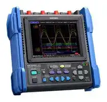


MR8880-20
Data Logger, Voltage, 4 Channel, 1 MS/s, SD Card, USB, LCD
- Manufacturer: HIOKI
- Product type:
- SVHC: To Be Advised
- Display Type: LCD
- Product Range: -
- Data Interface: SD Card, USB
- Maximum Samples: 1 MS/s
- Data Logger Type: Voltage
- No. of Channels / Inputs: 4 Channel
- Sensor / Measurement Type: -
| Delivery and price | |
|---|---|
| Units per pack | 1 |
| Price | 2836.2 € |
| Current stock | 10+ |
| Lead time | 30 days |
## MEMORY HiCORDER MR8880

## Capture high- to low-voltage signals in a single device

## Rugged, Professional and Ready for the Field

## **CAT III 600 V insulation performance**

- Maximum 600V AC/DC input - no need for a differential probe • 4 completely isolated channels let you simultaneously record data on a 3-phase power line plus have one extra channel

## **Tough against harsh environments**

- Operating temperature range: **-10°C to 50°C**

- Built to withstand mechanical shocks and vibrations (ships standard with side protectors)

## **Make settings easily with PRESETS**

Simply select what you’d like to measure and follow the onscreen instructions to select the appropriate settings. The recorder can be easily configured to measure voltage drops and power outages.

2

## Safe & Reliable Measurement

The MR8880 offers safe, reliable operation featuring CAT III 600 V isolated inputs in a compact yet durable design that excels at taking measurements in harsh environments.

## **CAT III 600 V isolated inputs (4 channels)**

Don’t let extreme temperatures keep you from taking measurements! ~

## **Built to withstand harsh environments**

: Even when operating on battery power, the MR8880 can take measurements from 0°C(32°F) to 40°C(104°F).

**Shown with optional printer unit.**

3

## Settings are as Easy as 1-2-3 with PRESETS

To configure the MR8880, you need only select what you’d like to measure—“Measure a commercial power supply,” “Monitor a power source for a voltage drop,” etc.—and follow the on-screen instructions to select the appropriate settings.

## **Example: Configuring the MR8880 to monitor a power source for a voltage drop:**

**==> picture [484 x 303] intentionally omitted <==**

**----- Start of picture text -----**<br>
Press the<br>“PRESETS” key. | valtate drop 0% sewer cutace. ote |<br>| cm. oan. B v Select “Measurement Guide” Select “Voltage drop of power outage, etc.”<br>Select what you’d like<br>to measure with the  • Basic Guide • Measure Power Supply on INSTNT<br>nied D> cursor keys. > • Measurement Guide • Measure Power Supply on RMS<br>• Load Set. » • Voltage drop of power outage, etc.<br>• Save data to media<br>“Voltage drop of power outage, etc” settings screen<br>1. Select the channel you wish to use.  Use • Not Use<br>-<br>1. Channel Settings Voltage drop of power outage, etc.     Select the power line voltage. 100V • 200V<br>CH1 (TES) Start when 100Vrms(141.4Vpeak) S@Hz drops to 9@Vrms(127.2Vp)     Select the frequency. 50Hz • 60Hz<br>CH2 Use Start when 100Vrms(141.4¥peak} S@Hz drops to 90¥rms(127.2Vp}<br>CH3 Use Start when 160Vrms(141.4Vpeak) S@Hz drops to 90Vrms(127.2Vp)     Select the threshold. 90/85/80/75/70/65/60 V<br>CH4 Use Start when 100Vrms(141.4V¥peak} S@Hz drops to 90¥rms(127.2Vp}<br>2. Select the recording length. 25ms/50ms/100ms/200ms<br>2.Recording Length Settings<br>Measure for 25ms after voltage drops 3. Save pre-triggered waveforms. Record • Do not record<br>4. Select whether to repeat  Only once • Repeatedly<br>3. Pre-trigger Settings     measurement.<br>Do not record waveform before voltage drop<br>    Select the desired save settings.  • Do not save<br>4. Repeat & Save Settings  • Save to CF card in Binary Format<br> • Save to CF card in Text Format<br>Measure only once in accordance with the set values.  • Save to USB memory in Binary Format<br>Save measured data Do not save<br> • Save to USB memory in Text Format<br>Start measurement »~ 4<br>Start measurement<br>Press the START key WV<br>Press START to<br>begin measuring. START<br>**----- End of picture text -----**<br>


## **Basic Guide**

## **Loading settings**

**==> picture [479 x 185] intentionally omitted <==**

**----- Start of picture text -----**<br>
Press the “PRESETS” key and  Press the “PRESETS” key and<br>select “Basic Guide” select “Loading settings”<br>Hiehoeed x 1/58] *<br>Highspeed ' 4 cs Sine Me 28. 0 8. PRESETS PRESETS<br>Realtime I ' V<br>'10-10-21  14:58:08<br>Select the high-speed or real-time function. Select the source from which to load settings.<br>(The auto-range settings can be enabled when using the high-speed function.) (Memory / CF card / USB memory)<br>Make the necessary settings in accordance  Select the settings file to load from a list of settings stored on the selected source<br>(Settings can be configured while checking the measurement waveform.)with information provided by the guide.  and press the “Load” key.<br>44<br>Start measurement Start measurement<br>**----- End of picture text -----**<br>


4

## Applications

The MR8880 provides a turnkey solution for both high-speed measurement at 1 MS/s and long-term measurement. Its ability to measure everything from high- to low-voltage signals allows it to play an important role in a variety of measurement scenarios.

Measure the instantaneous wave- **1** form at startup or a suddenly generated abnormal waveform. 0

## High-speed measurement using the high-speed function

l Fastest sampling period of 1 μs (measuring all channels simultaneously) l Measurement data is recorded in the instrument’s internal memory (1 MW).

n Recording Time (Internal memory)

|nRecording Time (Internal memory)(Internal memory)|nRecording Time (Internal memory)(Internal memory)|nRecording Time (Internal memory)(Internal memory)|||
|---|---|---|---|---|
|All channels (4 analog + 8 logic channels)|||||
|Time Axis Range<br>Sampling Speed<br>100μs/DIV<br>1 MS/s|Recording Interval<br>1μs|Max. Recording Time<br>1 s|||
|200μs/DIV<br>500 kS/s|2μs|2 s|||
|500μs/DIV<br>200 kS/s|5μs|5 s|||
|1ms/DIV<br>100 kS/s<br>10μs<br>2ms/DIV<br>50 kS/s<br>20μs<br>5ms/DIV<br>20 kS/s<br>50μs<br>10ms/DIV<br>10 kS/s<br>100μs<br>20ms/DIV<br>5 kS/s<br>200μs<br>50ms/DIV<br>2 kS/s<br>500μs<br>100ms/DIV<br>1 kS/s<br>1 ms<br>~~———~~||10 s<br>20 s<br>50 s<br>1m 40 s<br>3m 20 s<br>8m 20 s<br>16m 40 s|\/|**Example record of an abnormal**<br>**waveform**<br>A waveform recorded using a waveform<br>judgment trigger. The judgment area can<br>be displayed simultaneously.|


The maximum recording length is fixed regardless of the number of channels in use.

**==> picture [486 x 229] intentionally omitted <==**

**----- Start of picture text -----**<br>
Measure RMS value fluctuations for a power  Long-term measurement and recording us-<br>2 line over an extended period of time ing the real-time function<br>@ ‘<br>n  Recording Capacity Note: Use only Hioki CF cards that are guaranteed to operate with the HiCorder for continuous long-term recording. l  Recording interval of 100 μs to 1 min<br>All channels (4 analog + 8 logic channels), recording waveform (binary) data only l  Waveform data is saved directly in a binary format to a CF card or<br>Recording<br>Interval Internal memory 512MB 1GB 2GB USB memory.<br>(8MB) (9728) (9729) (9830)<br>100μs 1m 40s 1h 25m 20s 2h 46m 40s 5h 33m 20s<br>200μs 3m 20s 2h 50m 40s 5h 33m 20s 11h 6m 40s Record RMS values and<br>500μs 8m 20s 7h 6m 39s 13h 53m 19s 1d 3h 46m 39s instantaneous waveforms<br>simultaneously.<br>1ms 16m 40s 14h 13m 19s 1d 3h 46m 39s 2d 7h 33m 19s<br>2ms 33m 20s 1d 4h 26m 38s 2d 7h 33m 18s 4d 15h 6m 38s<br>5ms 1h 23m 20s 2d 23h 6m 34s 5d 18h 53m 14s 11d 13h 46m 34s<br>10ms 2h 46m 40s 5d 22h 13m 8s 11d 13h 46m 28s 23d 3h 33m 8s<br>20ms 5h 33m 20s 11d 20h 26m 15s 23d 3h 32m 55s 46d 7h 6m 15s<br>50ms 13h 53m 20s 29d 15h 5m 39s 57d 20h 52m 19s 115d 17h 45m 39s<br>100ms 1d 3h 46m 40s 59d 6h 11m 17s 115d 17h 44m 37s 231d 11h 31m 17s<br>200ms 2d 7h 33m 20s 118d 12h 22m 34s 231d 11h 29m 14s - ★ -<br>500ms 5d 18h 53m 20s 296d 6h 56m 26s - ★ -<br>1s 11d 13h 46m 40s - ★ -<br>2s 23d 3h 33m 20s<br>1 min 694d 10h 40m - ★ - - ★ - - ★ -<br>…<br>… …<br>… … …<br>… … … … …<br>**----- End of picture text -----**<br>


l Recording interval of 100 μs to 1 min l Waveform data is saved directly in a binary format to a CF card or USB memory.

- Maximum recording time is inversely proportional to number of recording analog channels.

- Because the actual capacity of a CF card is less than that indicated, , expect actual maximum times to be about 90% of those in the table.

- " ★ " exceeds 1 year.

• Proper operation is not guaranteed for extended recording periods (one year or longer). This type of operation impacts the product’s warranty period and service life.

Measure the phase voltages for all three phases of a three-phase motor **3** simultaneously. ~~o~~ Check for fluctuations in low-voltage **4** signals such as instrumentation or senC sor output. ‘ Investigate why your office’s power sup- **5** ply occasionally exhibits instability. 0 ‘

Four channels of isolated CAT III 600 V input The MR8880 can measure the voltages at different contacts without the need for a differential probe.

Thanks to its 14-bit, high-resolution A/D converter and the combination of a high-sensitivity 10 mV/div range and a 5 Hz filter (for noise rejection), the MR8880 can deliver stable measurement of sensor output.

The MR8880 is capable of mixed recording of RMS values, DC voltage, and logic signals, allowing it to simultaneously record data describing the interrelationships between equipment power supplies and UPS output and control signals.

5

## Functionality and Performance

The MR8880 delivers convenient functionality designed to maximize ease of use along with exceptional performance. See how this instrument can transform your concern and discontent to peace of mind and satisfaction.

Take home data for later viewing on a computer

Data can be saved directly to external media.

- l In addition to CF cards, the MR8880 can store data on handy USB memory sticks.

- l Data can be saved in real time to external media (at up to 10 kS/s).

- l External media can be switched while measurement continues.

If the recording interval is set to 100 μs, media must be swapped outwithin 20 seconds.

- l External media is protected in the event of an unexpected power outage during measurement.

By backing up the internal power supply until processing to save data to the external media completes, the instrument enables highly reliable data collection.

**==> picture [125 x 34] intentionally omitted <==**

**----- Start of picture text -----**<br>
CompactFlash<br>card USB memory<br>C sages<br>**----- End of picture text -----**<br>


Use only HIOKI CF cards, which are manufactured to strict industrial standards, for long-term storage of important data.

_Note: Operation of non-HIOKI CF cards is not guaranteed_

Can the MR8880 withstand the vibrations in a moving vehicle?

The instrument complies with JIS automotive vibration standards.

Thanks to its ability to withstand a high level of vibration, the MR8880 can be used to collect data in moving vehicles. Included side protectors further increase the device’s durability.

Will the screen be hard to read while taking measure- **3** ments outdoors? O What if there’s no power available in the vehicle **4** being tested?

The MR8880 features a 5.7-inch TFT color LCD that offers excellent visibility, even while taking measurements in an outdoor setting. The display is even engineered for easy viewing in the presence of reflections.a

## A high-capacity battery is available.

The MR8880 can be used continuously for 4 hours on battery power.

## Is the printer easy to use?

Loading recording paper is a snap thanks to the MR8880’s one-touch loading mechanism.

Quickly print data on-site.

~ (Real-time print function: 1s/div )

**==> picture [330 x 62] intentionally omitted <==**

**----- Start of picture text -----**<br>
Example printout<br>(actual size)<br>a “a4 /<br>ae<br>Simply load the recording paper roll and close the cover.<br>Shown with optional<br>printer unit.<br>**----- End of picture text -----**<br>


6 n Specifications (Accuracy guaranteed for 1 year)

## **Basic specifications**

|Measurement func-<br>tions|High-speed function (high speed recording)<br>Real-time function(actual time recording)|
|---|---|
|Number of channels|4 analog +  8 logic<br>Isolated analog channels, isolated input and outputs, logic has common GND.|
|Maximum samplingrate|1Msamples/s(1μs cycle,all channels simultaneously)|
|Memorycapacity|14bit × 1 M words/ch(1 word = 2 bytes,not expandible)|
|External memory|CF card slot × 1 (Up to 2 GB, supports FAT16 and FAT32 formats)<br>USB memory× 1(USB 2.0 -A receptacle)|
|Time accuracy (at 23°C)|Samplingtime accuracy: ±0.0005 %,Clockprecision: ±3s/day|
|Backup function<br>(reference value at<br>23°C)|Clock and settings: 10 years or more (at 25°C / 77°F)<br>Waveform backup function: Approx.  40 minutes<br>•When instrument ispowered off at least 3 minutes after beingturned on|
|External control|External trigger input, Trigger output, external start input, external<br>stopinput, status output,groundpin|
|Interface|USB: 1 port USB 2.0 High Speed mini-B receptacle<br>Functions: Configure settings/perform measurement using communications<br>commands: transfer file stored in CF/USB memory to computer (USB drive<br>mode)|
|Environmental condi-<br>tions for use<br>(no condensation)|Temperature range: -10°C (14°F) to 50°C (122°F)<br>Humidity range: -10°C (14°F) to 40°C (104°F), 80% rh or less<br>40°C (104°F) to 45°C (113°F), 60% rh or less<br>45°C (113°F) to 50°C (122°F), 50% rh or less<br>When powered by BATTERY PACK Z1000:<br>0°C (32°F) to 40°C (104°F), 80% rh or less<br>When rechargingthe Z1000: 10°C(50°F)to 40°C(104°F),80% rh or less|
|Environmental condi-<br>tions for storage<br>(no condensation)|Temperature range: -20°C (-4°F) to 60°C (140°F)<br>Humidity range: 80% rh or less (-20°C (-4°F) to 40°C (104°F)), 60% rh<br>or less<br>(40°C (104°F) to 45°C (113°F)), 50% rh or less (45°C (113°F)  to 60°C<br>(140°F))<br>BATTERY PACK Z1000: -20°C (-4°F) to 40°C (104°F) , 80% rh or less|
|Compliance<br>standard|Safety: EN61010    EMC: EN61326, EN61000-3-2, EN61000-3-3<br>Vibration resistance: JIS D 1601, Type 1: passenger vehicle,<br>Conditions: equivalent to Type A|
|Power requirements<br>Note: LR6/AA alkaline batteries<br>are not sufficient to power the<br>unit when it is connected with<br>the Printer Unit MR9000.  Use of<br>other power supplies is required.<br>(Continuous operating time is<br>given as a reference value at 23°C.)|1)AC ADAPTER Z1002: 100 to 240V AC (50/60 Hz)<br>2)BATTERY PACK Z1000: 7.2V DC<br>Continuous operating time: Approx. 3 hours with backlight on, approx.<br>3.5 hours with backlight off(AC adapter has priority when both are used)<br>3) LR6 (AA)×8<br>Approx. 40 minutes with backlight on. Approx. 50minutes with  back-<br>light off.(when used with AC adapter, AC adapter takes precedence)<br>4) 10 to 28V DC (using special order cable)|
|Charging functions<br>(reference value at 23°C)|Charging time is about 3 hours<br>(can be charged by connecting the AC adapter while the Z1000 battery<br>pack is attached)|
|Max. rated power|1) When instrument is powered with the Z1002 AC adapter or an<br>external DC power supply: 11 VA*1, 10 VA*2, 40 VA*3<br>2) When instrument is powered with the Z1000 battery pack;<br>9 VA*1, 8 VA*2, 22 VA*3<br>*1Real-time data storage, backlight on<br>*2Real-time data storage, backlight off<br>*3Real-time data storage, backlight on, with printer used|
|Dimensions, mass<br>(including battery pack)|205 mm (8.07 in)W × 199 mm (7.83 in)H × 67 mm (2.64 in)D, 1.66 kg<br>(58.6 oz) (printer detached)<br>303 mm (11.93 in)W × 199 mm (7.83 in)H × 67 mm (2.64 in)D,2.16 kg<br>(76.2 oz) (printer attached)|
|Accessories|Instruction manual ×1, AC adapter Z1002 ×1, Alkaline battery box<br>×1, Strap ×1, USB cable ×1, Application disk (Wave viewer Wv,<br>Communication commands table)×1|
|||
|**Function**||
|Presets|Select from basic measurement guide, example measurement guide,<br>and commands for loadinginternallystored settings.|
|Scaling function|Select decimal or scientific notation for each channel.<br>1) Scaling ratio: Select scaling ratio, offset value, and units.<br>2) Two-point configuration: Set input values, post-scaling values,<br>and units.<br>3) HIOKI sensor: Set HIOKI clamp-on probe and range value.<br>4) Output rate setting: Select scaled value per 1 V from a list.|
|Data protection|Open files are closed before the instrument turns itself off when a<br>power outage occurs while saving data to recording media. When<br>powering the instrument with a battery, open files are closed and access<br>to the media is stopped when remaining battery power falls below a<br>certain level.<br>*Valid when at least 3 minutes has elapsed since the instrument was turned on.|
|Reservation function|Upto 10 measurement start and measurement stopconditions can be set.|
|Other|Settings can be automatically loaded from internal memory or<br>media when the instrument is turned on. Up to 10 settings can be<br>saved in the instrument’s internal memory.|
|||
|**Printer**(Printer Unit MR9000 docks onto the main device)||
|Features|Printerpaper one-touch loading,high-speed thermalprinting|
|Printer paper|112 mm (4.4 in) × 18 m (59.06 ft), thermal paper roll (using 9234)<br>Recordingwidth: 100 mm, 10 div f.s., 1 div=10 mm(80 dot/div)|
|Recording speed|Max. 10 mm/s (0.39 inch/s)<br>(Printing is not supported when using alkaline batteries.)|


**==> picture [248 x 757] intentionally omitted <==**

**----- Start of picture text -----**<br>
High-speed function  (high speed recording)<br>Time axis 100μs to 100ms/div, 10 range, resolution: 100 points/div<br>1/100 of time axis ranges<br>Sampling period<br>(minimum sampling period 1 μs, all channels simultaneously)<br>Recording length 5 to 10000 divisions fixed (5division steps)<br>Automatic save func- Binary data, text data, calculation results, binary + calculation results,<br>tion text + calculation results, or NONE<br>Other save functions Save and delete function: ON/OFF<br>Screen settings Split screen (1, 2, or 4 segments), X-Y waveform compositing (1 screen)<br>Can record data from before the trigger point, 0 to 100 % of<br>Pre-trigger recording length; 13 settings, or user-configured<br>Backwards scrolling through past waveform data both during and<br>Waveform scrolling after measurement<br>Up to four arithmetic operations simultaneously<br>Calculation functions Average value, effective (RMS) value, peak to peak value,<br>maximum value, time to maximum value, minimum value, time to<br>minimum value, period, and frequency, area, X-Y area.<br>Real-time function  (actual time recording)<br>100μs to 500μs, 1ms to 500ms, 1s to 1min, 19 settings<br>Recording interval Display time axis: 10ms to 1day/div, 22 ranges<br>Real-time printing  ON/OFF<br>(with optional MR9000) *Simultaneous printing: Supported when using a time axis slower than 1 s/div.<br>Recording Time Continuous save to CF card or USB memory can be set ON/OFF<br>Envelope mode ON/OFF<br>The last 1 Mwords (before measurement was stopped) are saved in<br>Waveform recording the instrument’s internal memory (when envelope mode is on, 500<br>kwords).<br>Real-time save func- Binary data, text data, calculation results, binary + calculation<br>tion results, text + calculation results, or NONE<br>Split save: ON/OFF/fixed time<br>Other save functions Save and delete: ON/OFF<br>Eject media: Media can be ejected while saving data in real time.<br>1) Event marks can be input during measurement (up to 100 marks).<br>Event marks 2) Can move to waveform before or after an event mark based on<br>specified event number input.<br>Trigger function<br>Repeat recording Single/Repeat<br>High-speed function: Start<br>Trigger timing<br>Real-time function: Start, Stop, Start & Stop<br>Trigger conditions AND/OR supported for all trigger sources<br>Trigger sources can be selected for each channel. Instrument enters<br>free-run mode when all trigger sources are off.<br>1) Analog input CH1 - CH4<br>Trigger source 2) Logic input LA1 - LA4, LB1 - LB4 (4ch × 2 probes)<br>3) External trigger<br>4) Interval trigger: Fixed-time recording for specified measurement<br>interval (month/day/hours/minutes/seconds)<br>1) Level<br>2) In<br>3) Out<br>Trigger types 4) Voltage drop (High-speed function) : For AC 50/60 Hz power lines<br>5) Waveform judgment (High-speed function): For AC 50/60 Hz power lines<br>6) Logic<br>7) External: Rising edge/falling edge<br>Level setting resolution 0.1 % f.s. (f.s.=10 div)<br>High-speed function: 7 settings from 10 to 1000 samples or OFF<br>Trigger filter Real-time function: ON/OFF<br>Trigger output Open collector (5 V output, active Low)<br>Analog input (Accuracy defined at 23° ±5°C, 80% rh or less, for measurements taken following zero adjustment 30 minutes  after instrument is turned on)<br>Measurement  4-channel voltage measurement; switchable between instantaneous<br>functions value (waveform) and RMS value<br>Input connectors Isolated BNC connector (input impedance 1 MΩ, input capacitance 7 pF)<br>600 V  AC, DC  CAT III  / 300 V  AC, DC  CAT IV<br>Max. rated voltage to<br>earth (with input isolated from the unit, the maximum voltage that can be applied between<br>input channel and chassis and between input channels without damage)<br>10 mV to 100 V/div, 13 ranges, full scale: 10 div, AC voltage that can<br>Measurement range be measured and displayed using high-speed function: 600 Vrms<br>Low-pass filter: 5 Hz/50 Hz/500 Hz/5 kHz/50 kHz<br>Measurement resolu-<br>tion 1/640 of measurement range (using 14-bit A/D conversion, at × 1)<br>Highest sampling rate 1 MS/s (simultaneous sampling in 4 channels)<br>Instantaneous value<br>measurement accuracy [±0.5% f.s. (after zero-adjust)]<br>RMS accuracy: ±1.5% f.s. (30Hz to 1kHz) ±3% f.s. (1kHz to 10kHz)<br>RMS measurement Response time: 300ms (rising edge 0 to 90% of full scale with filter off)<br>Crest factor: 2<br>Frequency charac- DC to 100 kHz ±3dB<br>teristics<br>Input coupling DC/GND<br>Max. rated voltage  600 V AC, DC  (maximum voltage which when applied to between input<br>between terminals terminals does not damage them)<br>**----- End of picture text -----**<br>


7

n Appearance and Dimensions

## **Screen display**

|Display|5.7-inch VGA-TFT color LCD(640 × 480dot)|
|---|---|
|Waveform display<br>scale|Time axis: × 10 to × 2 (zoom view supported for high-speed<br>recording only), × 1, × 1/2 to × 1/2,000<br>Voltage axis: × 20 to × 2,× 1,× 1/2 to × 1/10|
|Comment input|Titles and comments input for individual channels|
|Logic waveform dis-<br>play|Select 2 recording widths; display positions can be set separately|
|Display items|Waveform display; simultaneous display of waveform and gage;<br>simultaneous display of waveform, gage, and settings; simultaneous<br>display of waveform and calculation results; simultaneous display of<br>waveform and cursor values (A/B cursor values)<br>The following display items are supported when using real-time<br>functionality:|
|Monitor function|Value(instantaneous value or RMS value)and measured waveform<br>(monitor screen display with refresh rate of 0.5 sec)<br>Displaydigits: 5|
|Instantaneous value<br>display|Time: Display of time elapsed since start of measurement or trigger point<br>Date: Display of date and time at which data was captured<br>Number of data points: Display of number of data points captured since<br>start of measurement|
|Other display<br>functions|• Cursor measurement(two cursors [A/B], support for all channels)<br>• Upper and lower limits can be set(to align waveform amplitude with<br>upper and lower limits).<br>• The zero position of the analog waveform can be moved in 1% steps.<br>• The waveform display can be set to any of 24 colors.<br>• Zero adjustment can be performed for all channels and ranges at once.|


Analog input (Isolated BNC terminal)

**==> picture [253 x 178] intentionally omitted <==**

**----- Start of picture text -----**<br>
USB terminal<br>(for USB memory)<br>USB terminal<br>(for PC communication)<br>|<br>ts vt 1<br>Logic probe<br>terminal<br>External<br>E e<br>control<br>terminal<br>2 44D, we:<br>(8.07 in)205 mm >| CF card slot<br>67 mm (2.64 in)<br>199 mm (7.83  in)<br>**----- End of picture text -----**<br>


**==> picture [126 x 7] intentionally omitted <==**

**----- Start of picture text -----**<br>
with PRINTER UNIT MR9000 attached<br>**----- End of picture text -----**<br>


n PC Software Specifications   Bundled with the MR8880 in the CD-R

## **Wave Viewer (Wv) Software**

- Simple display of waveform file • Text conversion: convert binary data file to text format, with selectable space or tab separators in addition to CSV, and specifiable

- Functions section, thinning available • Display format settings: scroll functions, enlarge/reduce display, display channel settings

- • Others: voltage value trace function, jump to cursor/trigger position function

- Operating environment Windows 10/8/7 (32/64-bit)

**==> picture [146 x 88] intentionally omitted <==**

**----- Start of picture text -----**<br>
,J<br>=<br>ar a<br>303 mm<br>a (11.93 in)<br>199 mm (7.83  in)<br>**----- End of picture text -----**<br>


## n Specifications of Options (sold separately)

|Function|Detection of voltage signal or relaycontact signal for High/Low state recording|
|---|---|
|Input|4 channels(common ground between unit and channels), digital/contact input,<br>switchable(contact input can detect open-collector signals)<br>Input resistance: 1 MΩ(with digital input, 0 to +5 V)<br>500 kΩ or more(with digital input, +5 to +50V)<br>Pull-upresistance: 2 kΩ(contact input: internally pulled upto +5 V)|
|Digital input threshold|1.4V/ 2.5V/ 4.0V|
|Contact input<br>detection resistance|1.4 V: 1.5 kΩ or higher(open)and 500 Ω or lower(short)<br>2.5 V: 3.5 kΩ or higher(open)and 1.5 kΩ or lower(short)<br>4.0 V: 25 kΩ or higher(open)and 8 kΩ or lower(short)|
|Detectablepulse width|500 ns or longer|
|Max. allowable input|0 to +50V DC(the maximum voltage that can be applied across input pins without<br>damage)|


- Cable length and mass: Main unit cable 1.5 m (4.92 ft), input section cable 1 m (3.28 ft), approx. 320 g (11.3 oz)

_**Note:** The unit-side plug of the MR9321-01 is different from the MR9321._

## **LOGIC PROBE MR9321-01**

|Function|Detection of AC or DC relay drive signal for High/Low state recording<br>Can also be used forpower line interruption detection|
|---|---|
|Input|4 channels(isolated between unit and channels), HIGH/LOW range switching<br>Input resistance: 100 kΩ or higher(HIGH range), 30 kΩ or higher(LOW range)|
|Output (H) detection|170 to 250 V AC, ±DC 70 to 250 V(HIGH range)<br>60 to 150 V AC, ±DC 20 to 150 V(LOW range)|
|Output (L) detection|0 to 30 V AC, ±DC 0 to 43 V(HIGH range)<br>0 to 10 V AC, ±DC 0 to 15 V(LOW range)|
|Response time|Rising edge 1 ms max., falling edge 3 ms max.(with HIGH range at 200 V<br>DC, LOW range at 100 V DC)|
|Max. allowable input|250 Vrms(HIGH range), 150 Vrms(LOW range) (the maximum voltage that can<br>be applied across input pins without damage)|


Cable length and mass: 70 cm (2.30 ft), Output side: 1.5 m (4.92 ft), 170g (6.0 oz)

|Measurement modes|P9000-01: For waveform monitor output, Frequency properties: DC to 100 kHz<br>-3 dB<br>P9000-02: Switches between waveform monitor output/AC effective value output<br>Wave mode frequency properties: DC to 100 kHz -3 dB, RMS mode frequency<br>properties: 30 Hz to 10 kHz, Response time: Rise 300 ms, Fall 600 ms|
|---|---|
|Division ratio|Switches between 1000:1,100:1|
|DC output accuracy|±0.5 % f.s.(f.s. = 1.0 V, division ratio 1000:1),(f.s. = 3.5 V, division ratio 100:1)|
|Effective value mea-<br>surement accuracy|±1 % f.s.(30 Hz to less than 1 kHz, sine wave), ±3 % f.s.(1 kHz to 10 kHz,<br>sine wave)|
|Input resistance/capacity|H-L: 10.5 MΩ,5pF or less(at 100 kHz)|
|Maximum input voltage|1000 V AC,DC|
|Maximum rated volt-<br>age toground|1000 V AC, DC (CAT III)|
|Operating<br>temperature range|-40°C to 80°C (-40°F to 176°F)|
|Power supply|(1) AC adapter Z1008(100 to 240 V AC, 50/60 Hz), 6 VA(including AC<br>adapter), 0.9 VA(main unit only)<br>(2) USB bus power(5 V DC, USB-microB terminal), 0.8 VA<br>(3)Externalpower source 2.7 V to 15 V DC, 1 VA|
|Accessories|Instruction manual ×1,Alligator clip×2,Carryingcase ×1|


## **WAVE PROCESSOR 9335**

|Distribution media|One CD-R|
|---|---|
|Operating<br>environment|Computer running under Windows 10/8/7 (32/64-bit)|
|Display functions|Waveform display,  X-Y display,  Digital value display,  Cursor function,<br>Scroll function,  Maximum number of channels(32 channels analog, 32<br>channels logic),Gauge display (time, voltage axes),Graphical display|
|File loading|Readable data formats(.MEM, .REC, .RMS, .POW),<br>Maximum loadable file size: Maximum file size that can be saved by a<br>given device(file size maybe limited dependingon the computer configuration)|
|Data conversion|**Conversion to**CSV format,  Tab delimited,  Space delimited,  Data culling<br>(simple),  Convert for specified channel,  Batch conversion of multiple<br>files|
|Print functions|Printing image file output(expanded META type, “.EMF”),<br>Supported printer: usable on any printer supported by operating system<br>Print formatting:(1 up, 2-to-16 up, 2-to-16 rows, X-Y 1-to-4 up,preview,  hard copy)|
|Other|Parameter calculation,  Search,  Clipboard copy,  Launching of other appli-<br>cations|


**==> picture [507 x 15] intentionally omitted <==**

**----- Start of picture text -----**<br>
Co MR8880  Options in Detail<br>**----- End of picture text -----**<br>


**==> picture [504 x 622] intentionally omitted <==**

**----- Start of picture text -----**<br>
*Voltage is limited to the specifications of the input section *A separate power supply (CT955x) is required in order to use a high-precision current sensor.<br>Recommended ALLIGATOR CLIP  L9790-01 Red/black set attaches to the ends  *Only sensors with ME15W (12-pin) terminals (-05 type) can be connected to the CT955x.*The separately available Conversion Cable CT9900 is required in order to use a sensor with PL23 (10-pin) terminal.<br>of the cables L9790 POWER SUPPLY for Current Sensors<br>CONTACT PIN  9790-03 SENSOR UNIT CT9555 1ch, with Waveform output<br>Red/black set attaches to the ends<br>of the cables L9790 CONNECTION CORD L9217<br>CONNECTION CORD  L9790 GRABBER CLIP  9790-02 Cord has insulated BNC connectors at both ends, 1.6 m (5.25 ft) length<br> Flexible φ 4.1 mm (0.16 in) thin  Red/black set attaches to the ends<br>dia., cable allowing for up to 600  of the cables L9790 PL23 (10-pin) - ME15W (12-pin) conversion<br>V input. 1.8 m (5.91 ft) length * When this clip is attached to the end of the  CONVERSION CABLE CT9900<br>* The end clip is sold separately. L9790, input is limited to CAT II 300 V. Red/black set.  Convert  PL23 (10-pin) terminal to ME15W (12-pin) terminal<br>Up to 1000 A (High precision) *ME15W (12-pin) terminal type<br>Model : MEMORY HiCORDER MR8880<br>High-precision pull-through type, monitor the waveforms of DC to distorted AC current<br>28? L9790 L9790-01 9790-03 9790-02 Model No. (Order Code) 4 (Note) AC/DC CURRENT SENSOR  CT6875, 2 MHz band width, 500A<br>*Voltage is limited to the specifications of the input sectionCONNECTION CORD  L9198 φ 5.0 mm (0.20 in) dia., cable allowing  ——— MR8880-20 *Test leads are not included. Purchase the leads appropriate for your application separately (4ch, printer unit option) Monitor the waveforms of DC to distorted AC currentAC/DC CURRENT PROBE  CT6844-05AC/DC CURRENT PROBE  CT6845-05, 200 kHz band width, 500A, 100 kHz band width, 500A<br>for up to 300 V input. 1.7 m (5.58 ft)  AC/DC CURRENT PROBE  CT6846-05, 20 kHz band width, 1000A<br>length, small alligator clip<br>Precautions when connecting a high-precision current sensor to a Memory HiCorder<br>PRINTER UNIT MR9000 Connecting to the MR8880/MR8875/MR8870<br> Printing width 100 mm (3.94 in),  • High-precision current sensor (ME15W) + CT9555 + BNC cable → MR8880<br>used together with the MR8880- • High-precision current sensor (PL23) + CT9900 + CT9555 + BNC cable → MR8880<br>CONNECTION CORD  L9197 20 main body, includes 1 roll of recording paper Other current sensor types<br> φ 5.0 mm (0.20 in) dia., cable allowing  GRABBER CLIP  9243 The MR8880 can be used with various types of current sensors and<br>VIAR for up to 600 V input. 1.8 m (5.91 ft)   Attaches to the tip of the banana  \— probes. For details, see product information on Hioki’s website.<br>length, a detachable large alligator  plug cable, CAT III 1000 V, 196  RECORDING PAPER 9234<br>clips are bundled mm (7.72  in) length  112 mm (4.41 in) × 18 m (59.06 ft),  The CM7290 (available separately) is required in order to use these current sensors.<br>*Voltage to ground is within this product's specifications.  roll type, 10 rolls/set 100 A to 2000 A (Medium speed)<br>Separate power source is also required. AC/DC CURRENT SENSOR CT7631,<br>. —<br>(Auto zero  CT7731)<br> DC, 1 Hz to 10 kHz (-3dB), 100 A, 1 mV/A output<br>AC/DC CURRENT SENSOR CT7636,<br>(Auto zero  CT7736)<br>DIFFERENTIAL PROBE  DIFFERENTIAL PROBE  AC ADAPTER   DC, 1 Hz to 10 kHz (-3dB), 600 A, 1 mV/A output<br>P9000-01Waveform only, up to 1 kV AC/DC, band width up to 100kHz  Waveform/RMS value switch-P9000-02able, up to 1 kV AC/DC, band   100 to 240 V ACZ1008 AC/DC CURRENT SENSOR CT7642, (Auto zero  CT7742)<br>width up to 100kHz  DC, 1 Hz to 10 kHz (5 kHz), 2000 A, 1 mV/A output<br>DISPLAY UNIT CM7290<br>*For P9000. Inquire with your Hioki distributor.<br> Provides measurement, display, and output<br>(1) Bus powered USB cable MR8880 + MR9000 functionality when used with the CT7000s.<br>(2) USB(A)- Micro B cable DISPLAY UNIT CM7291<br>a (3) 3-prong cable Includes a PC card adapter with the 9728/9729, and  the 9830 ih. ‘:  with built-in Bluetooth® wireless technology<br>Use only CF Cards or USB drive sold by HIOKI. Compatibility and  OUTPUT CORD  L9095<br>*Voltage to ground is within this product's specifications. Separate power source is also required. performance are not guaranteed for CF cards/USB memory stick made by other manufacturers. You may be unable to read from or save data to such cards. Ze  Connect to BNC terminal, 1.5 m (4.92 ft) length<br>0 DIFFERENTIAL PROBE 9322 PC CARD 2G 9830<br> For up to 1kV AC or 2kV DC,   2 GB capacity 500 A to 5000 A *For commercial power lines, 50/60 Hz<br>frequency band width up to 10MHz PC CARD 1G 9729 CLAMP ON PROBE  9018-50<br> 1 GB capacity  Good phase characteristics, Frequency<br>AC ADAPTER 9418-15 characteristics: 40 Hz to 3 kHz, 10 to 500 A<br> 100 to 240 V AC. PC CARD 512M 9728 512 MB capacity — AC range, output 0.2 V AC f.s.<br>CLAMP ON PROBE  9132-50<br>* Only the small terminal types can be used. USB DRIVE Z4006 16 GB, Long-life, High-reliability   Frequency characteristics: 40 Hz to 1 kHz, 20 to 1000 A AC range, output 0.2 V AC f.s.<br>SLC Flash Memory<br>AC FLEXIBLE CURRENT SENSOR<br>CT9667-01/-02/-03<br> 10 Hz to 20 kHz, 5000 A/ 500 A AC, 500<br>mV/f.s. output, φ 100 to 254 mm (3.94 to<br>: 10.00 in), 3 loop diameters<br>LOGIC PROBE  9320-01 LOGIC PROBE  MR9321-01<br> 4-channel type, for voltage/contact signal   4 isolated channels, ON/OFF<br>ON/OFF detection (response pulse width  detection of AC/DC voltage  Leak Current *For commercial power lines, 50/60 Hz<br>500 ns or more, miniature terminal type) (miniature terminal type)<br>CLAMP ON LEAK HiTESTER  3283<br> 10 mA range/10 μA resolution to 200 A range,<br>with monitor/analog output 1 V f.s.<br>*Z1002 is a bundled accessory<br>OUTPUT CORD  L9095<br> Connect to BNC terminal, 1.5 m (4.92 ft) length<br>AC ADAPTER  9445-02<br> 100 to 240 V AC<br>CONNECTION CORD  AC ADAPTER  9445-03<br>L9217  For EU 100 to 240 V AC<br>CARRYING CASE C1003  Cord has insulated BNC  AC ADAPTER Z1002 BATTERY PACK Z1000<br> Includes compartment for  connectors at both ends, for signal output, 1.6 m (5.25 ft)  For main unit, 100 to 240 V AC  NiMH, Charges while installed in the main unit<br>options, soft case type length<br>®BRN<br>NON-CONTACT AC VOLTAGE  NON-CONTACT  AC VOLTAGE<br>PROBE SP3000-01 AC VOLTAGE  PROBE<br> 5 Vrms rated, 10 Hz to 100 kHz  PROBE SP3000 SP9001<br>band width  Sold individually  Sold individually<br>Input cable (A)<br>Input cable (B)<br>Printer options<br>Input cable (D)<br>Custom cable<br>Input cable (E)<br>Storage media<br>Logic signal measurement<br>Other options Power supply<br>Non-contact Voltage measuring<br>**----- End of picture text -----**<br>


_Note: Company names and product names appearing in this brochure are trademarks or registered trademarks of various companies._

DISTRIBUTED BY

**HEADQUARTERS** 81 Koizumi, Ueda, Nagano 386-1192 Japan https://www.hioki.com/

All information correct as of Mar. 31, 2022. Contents are subject to change without notice.

MR8880E19-23E      Printed in Japan
Updated at June 4, 2026
Hioki is a distinguished manufacturer recognized globally for its innovative and precision-driven test and measurement solutions. The company develops advanced, high-quality instruments designed to meet the rigorous demands of engineers, technicians, and researchers across the electronics, automotive, and energy sectors. Within its comprehensive portfolio of measurement technology, Hioki is particularly noted for its highly reliable data acquisition and data logging systems. Their precision dataloggers are meticulously engineered to gather crucial information with unparalleled accuracy, enabling professionals to seamlessly monitor, record, and analyze complex electrical and environmental phenomena over time. Built with a commitment to user-friendly operation and robust performance, Hioki instruments are designed to streamline complex workflows and accelerate both research and industrial diagnostics. By delivering exceptional build quality and consistent, verifiable results, the brand remains a trusted choice for critical measurement tasks and long-term data collection.
About Novapart
Novapart is a B2B electronic component broker specialising in stock shortages and cost reduction. We source hard-to-find parts and identify compliant alternatives across a catalogue of 410,000+ components from 500+ manufacturers.
Learn more →Stock Shortage Specialist
When a component is unavailable, discontinued or has an unacceptable lead time, we tap into our network of vetted European and Asian distributors to source what you need — without compromising on quality or traceability.
Request a quote →Compliant Alternatives
We identify pin-to-pin, electrically equivalent substitutes that meet the same certifications (RoHS, AEC-Q100, REACH) as your original specification — validated against datasheets, not just part numbers. Often at a lower cost.
BOM Analysis service →