
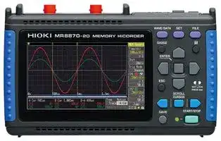


MR8870-20
Data Logger, 2 Chanel Analog + 4CH Logic, Waveform & RMS Fluctuation, 1MS/s, 12Bit, 10 mV to 50 V
- Manufacturer: HIOKI
- Product type:
- SVHC: To Be Advised
- Display Type: LCD
- Product Range: -
- Data Interface: CF Card, USB
- Maximum Samples: 2 MS/s
- Data Logger Type: Memory Recorder, RMS Recorder
- No. of Channels / Inputs: 6 Channel
- Sensor / Measurement Type: -
| Delivery and price | |
|---|---|
| Units per pack | 1 |
| Price | 1140.57 € |
| Current stock | 10+ |
| Lead time | 30 days |
## MEMORY HiCORDER MR8870

## th d<= =A .‘ay — af **Oscilloscope-like Waveform Observation,** ' a ¥, ™ **Plus Recording of RMS Variations - In a Single Device!**

##

## **RMS recording function makes its debut on this device!**

Enhancing the ultra-compact oscilloscope-functioning Hioki 8870, the new MR8870 features a new RMS recording mode and real-time save to a CF card.

- n **Measure safely, with isolated input for all channels**

   - Test commercial power lines with ease of mind thanks to isolated input for both channels

- n **Monitor instantaneous waveforms on-site**

   - High-speed waveform observation/recording with 1 M sampling, despite compact size

- n **Monitor fluctuations in commercial power lines**

   - Real-time recording of data to CF card with 1 ms recording interval in a compact package

- n **Synchronize two HiCORDERs together to measure three-phase lines and other channels needing three or more channels**

   - Bundled PC application enables integration/observation of synchronized data from two HiCORDERs on a single screen

2

## **Memory Recorder**

## An oscilloscope in the palm of your hand Capture unpredictable phenomena using waveforms !

## n **Recording of EV and HEV starting current waveforms**

The MR8870 can be used with a clamp-on AC/DC i / \ current sensor to observe the current waveform at motor start. Hioki’s clampon sensor line covers a frequency band ranging from DC to frequencies of Be The photograph shows the MR8880, the MR8870’s four-channel 10 kHz and higher. sister product.

## n **Check inverter output waveforms**

Inverter performance analysis requires simultaneous observation of the high frequency carrier signal and the low frequency fundamental waveform being switched. The combination of high-speed sampling capability and highcapacity memory make these observations possible. For current waveform observations, use Hioki clamp sensors capable of high-frequency measurements without direct electrical contact.

## n **Recording of motor rush current**

Motor power-on inrush current waveforms can be precisely recorded. J The Clamp On Probe the 9018-50 is available for current measurement, as is the Clamp On Leak HiTester 3283. In addition, to measure direct current waveforms, a variety of Current  meters Ny such as the CLAMP ON AC/DC HiTESTER WaMi ‘il 3284/3285 are available upon request.

## n **CB timing measurements**

Analyze the relationships of multi-point logic signals and analog waveforms to detect timing issues that can affect power supply circuit breakers. Use logic probes to record relay operations on up to four channels, or use the Differential Probe P9000 for three-phase 440 v power line measurements and for support of CAT III 600 V measurement categories.

**==> picture [104 x 54] intentionally omitted <==**

**----- Start of picture text -----**<br>
3285<br>Signal input requires Connection Cord<br>L9095 (for use with BNC terminals).<br>**----- End of picture text -----**<br>


**==> picture [28 x 6] intentionally omitted <==**

**----- Start of picture text -----**<br>
9018-50<br>**----- End of picture text -----**<br>


**==> picture [249 x 47] intentionally omitted <==**

**----- Start of picture text -----**<br>
CAT IV 600 V CAT III 600 V 9322<br>For high voltage measurement<br> DIFFERENTIAL PROBE 9322<br>For high voltage measurement<br> DIFFERENTIAL PROBE P9000-01, P9000-02<br>**----- End of picture text -----**<br>


## n **Analysis of sequence controller issues**

When sequence controllers being used in applications such as production and testing lines stop due to errors or generate warning output, potential causes include momentary AC power interruptions and brownouts. The MR8870 is ideal for analyzing the operation of such systems since it can record the correlation of sequence relay signals, AC power circuits, and DC voltage circuits as waveforms using power supply anomalies as a trigger.

3

## **RMS**

## **Recorder**

## A pen-free recorder in the palm of your hand Long-term RMS fluctuation recording !

## Pen- and paper-free recording

## A substitute for the Hioki Micro HiCorder

_The photo above shows the Hioki 8205-10 and 8206-10 Micro HiCorders. These products are no longer available._

## **RMS value calculation method**

RMS values for three AC waveform cycles are calculated 1,000 times every second (see figure below). Readings other than maximum and minimum values are eliminated based on the set recording interval, and the resulting data is displayed and saved.

## n **AC RMS data recording**

Use the device in conjunction with an AC voltage input and a clamp current sensor to record RMS values for current. Input instantaneous waveforms are acquired via high-speed sampling at 200 μsec. RMS data is staggered at a rate of 1000 times per second as it is computed – not even abrupt fluctuations will escape notice.

## n **RMS data recorded in internal memory**

The RMS recorder can output data into the internal memory at rates of up to once per millisecond. Internal memory recordings of up to 10,000 div (1 million data items) are supported. Furthermore, if you set automatic saving to storage media, the device writes data to the media (at each recording interval) in real time as it makes measurements.

_* A new data file is created for each 10,000 div worth of data._

_* It is possible to save the data repeatedly up until the media’s full capacity is reached, but after that periods of dead time (when measurement is not possible) will occur every 10,000 div._

~~Duration of 3 cycles~~ 1/1000 sec ~~Duration of 3 cycles — ——"I*~~

4

## Compact and lightweight

## Small-bodied design for ease of portability

Volume is just 30% and weight just 40% of Hioki's 4-channel Memory HiCorder, the MR8880 – a 70% and 60% reduction, respectively.

A waveform measurement instrument that you can slip into your briefcase and carry anywhere. Should you suddenly discover you need it on a work trip, you can simply take it out and begin to use it, just as you would a tester.

**==> picture [191 x 68] intentionally omitted <==**

**----- Start of picture text -----**<br>
101 mm<br>(3.98 in)<br>| Sse Se eee a ss -<br>° rs a<br>176 mm 41 mm<br>— (6.93 in) — (1.61 in)<br>**----- End of picture text -----**<br>


Intuitive, no-fuss operation Built-in Setup Wizard to help you get started

**==> picture [123 x 29] intentionally omitted <==**

**----- Start of picture text -----**<br>
Activate the Setup Wizard Setting<br>**----- End of picture text -----**<br>


**==> picture [150 x 29] intentionally omitted <==**

**----- Start of picture text -----**<br>
Real-Time waveform monitoring Setting<br>**----- End of picture text -----**<br>


When powered on, the Settings screen appears along with the waveform monitor, and the new Setup Wizard blinks. By activating the Setup Wizard, you can easily navigate by following the simple instructions. Soon you will be operating the device like a seasoned professional.

The help text crawls along the bottom of the screen, describing the function of the setting at the blinking cursor. The enhanced “Waveform Monitor” window with level meter display facilitates changes to settings by simultaneously displaying real-time input waveforms.

## Select mode at start-up

No unnecessary fuss before you can start working. You select which measurement mode to use (memory recorder or RMS value recorder) when you switch on the device.

Choose the mode once, and you’ll never need to select it again.

5

Data analysis in tandem with a PC Dedicated PC application program bundled as standard accessory

## n **Pseudo-real-time data recording to media (MEM data)**

The memory recorder’s instantaneous waveform recording functionality automatically saves data to storage media in a way that minimizes the interval during which the instrument cannot perform measurement while data is being saved (socalled dead time). This approach allows the instrument to

write data up to the set recording length to media in real time (for each sampling interval) while continuing measurement with a time axis setting of 50 ms/div. or slower.

## n **Binary data (MEM/RMS data) loadable into PC**

You can copy data saved on the CF card to a PC in two ways: via the card, or by connecting the MR8870 to the PC with a USB cable. The bundled PC application lets you display waveforms on the PC and print them out.

_* The MR8870 is not provided with a communication function for controlling it from a PC connected to it with a USB cable._

## n **Synchronize two HiCorders together for 4ch recording! (MEM data)**

For those times when 2-channels are just not enough, synchronize two MR8870’s using the external trigger I/ O terminals (apply the trigger output from one to the external trigger input of the other). Then use synchronous start to automatically record four channels of measurement data to a CF card. I |

l Use the bundled software to composite waveform files. For example, to monitor the waveforms of a 3P 200 V line, you can use two HiCorders at the same time and view the waveforms of all 4 channels on the same screen on the PC.

## n **Waveform display and printing, and CSV conversion with PC (MEM data, RMS data)**

Open a data file with the dedicated Wave Processor (PC application program) for the MR8870/8870, to import and print waveforms with your own arrow and figure annotations. Of course, screen data can be copied and pasted into common Word and Excel documents to easily create reports.

## n **Features of the Dedicated Wave Processor Program (supplied accessory)**

- l Designed especially for MEMORY HiCORDER MR8870/8870

- Application program displays and prints waveforms, and converts measurement data to CSV text files on a Windows PC.

- l Provides X-Y display capability not available on the HiCorder

- l Generate reports using templates, with figure annotations and entered comments

- l Multiple files can be batch-converted to CSV data

- l Use two HiCorders to monitor 3 or 4 channels of waveforms that are measured using the same time axis range on the same PC window.

6

n Specifications  (Accuracy guaranteed for 1 year, Post-adjustment accuracy guaranteed for 1 year) Basic specifications Memory r

|Memoryrecorder(high-speed recording)|Memoryrecorder(high-speed recording)|
|---|---|
|Measurement<br>targets|Instantaneous waveform of DC to AC waveform recording / monitor|
|Time axis|100 μs to 5 min/div(100 samples/div)20 ranges<br>Time axis zoom: ×2 to ×10 in 3 stages, compression: 1/2 to 1/1000<br>in 9 stages|
|Sampling period|1/100 of time axis range(minimum 1μsperiod)|
|Recording length|20 to 20,000 div, or continuous(available at 50 ms/div to 5 min/div only)<br>_Note: limited by timebase, only the last 20,000 div are saved_|
|Pre-trigger|Record data from before the trigger point at 0 to 100% of the<br>recordinglength in 13 stages|
|Calculation<br>functions|• Numerical calculation: Up to four simultaneous calculations (common<br>to all channels), calculation results are saved to CF card<br>• Calculation contents: average, peak-peak, maximum and minimum val-<br>ues, RMS, period and frequency<br>• Calculation range: specified by A/B cursors or whole recording length<br>• Waveformprocessing: N/A|


## Measurement functions Memory recorder (high-speed recording), RMS recorder (50/60 Hz, or DC only)

|Measurement functions|Memoryrecorder(high-speed recording),RMS recorder(50/60 Hz, or DC only)|
|---|---|
|No. of channels|2 analog and 4 logic channels(For analog inputs, channels are isolated<br>form each other and from frame GND. For logic terminals, all channels<br>has common GND.)|
|Maximum samplingrate|1 MS/s(1μsperiod,all channels simultaneously)|
|Memorycapacity|12 bits × 2 M-Words/ch|
|Removable<br>storage|CF card Type I slot(standard equipment)×1: Up to 2 GB, supports FAT, or<br>FAT-32 format<br>Memory items: Setting condition, measurement data (binary or text),<br>screen shot, result of numerical calculation, reduced text savingdata|
|Backup function|Clock and settings: 5 years or more(@25°C 77°F)<br>Waveform backup function: available when Battery pack 9780 is<br>installed with charge remaining or AC adapter is connected(up to<br>100 hours with fullycharged battery pack).|
|Control terminals|Terminal block: External trigger input,trigger output|
|External interface|USB: USB 2.0, mini-B receptacle ×1 port,<br>Function: Transfer files from the installed CF card to a PC via<br>USB cable, but communication functions such as the capability to<br>change HiCorder settings from the PC are notprovided.|
|Displaytype|4.3-inch TFT color LCD (480 × 272 dots)|
|Display resolution|Waveform section: 20 div (time axis) × 10 div (voltage axis)<br>(1 division = 20 dots × 20 dots)|
|Display languages|MR8870-20: English, Japanese(Default settings: English)<br>MR8870-30: Chinese, English, Japanese(Default settings: Chinese)<br>**_Note:_**_Korean(special order only, please contact Hioki)_|
|Environmental condi-<br>tions(no condensation)|Operation: 0°C (32°F) to 40°C (104°F), 80 % rh or less<br>Storage: -10°C(14°F)to 50°C(122°F), 80 % rh or less|
|Compliance<br>standard|Safety: EN61010,<br>EMC: EN61326, EN61000-3-2, EN61000-3-3|
|Power supply|• AC Adapter Z1005: 100 to 240 V AC, 50/60 Hz<br>• Battery pack 9780: continuous operation times: approx. 2 hours<br>(reference value at 25°C/77°F, waiting for trigger) (AC adapter has priority<br>when used in combination with battery pack)<br>• DC power supply: 10 to 16 V DC(please contact your Hioki distributor<br>for connection cord,max. 3 m/9.84 ft length)|
|Power<br>consumption|30 VA max.(When using the AC adapter and charging internal battery pack 9780)<br>10 VA max.(When using external DC power supply and charging internal battery<br>pack 9780)<br>3 VA max.(When using the battery pack 9780)|
|Charging functions|The installed battery pack charges when the AC adapter is connected.<br>Charging time is about 200 minutes(reference value at 25°C/77°F)<br>_Notes: Charging time depends on battery condition. Charging is disabled to_<br>_protect the battery at ambient temperatures out of 5°C(41°F) to 30°C(86°F)._|
|Dimensions and<br>mass|Approx. 176 mm(6.93 in)W × 101 mm(3.98 in)H × 41 mm(1.61 in)D,<br>600g (21.2 oz) (with the Battery pack 9780 installed)|
|Accessories|Instruction Manual ×1, Measurement Guide ×1, AC adapter Z1005 ×1,<br>Strap ×1, USB cable ×1, Application Disk(Wave Processor Program for<br>the 8870)×1,Protection sheet 9809 ×1|
|Trigger functions (For memoryrecorder only)||
|Trigger modes|Single,continuous|
|Trigger sources|Two analog channels, four logic channels, external trigger(falls<br>below 2.5 V, or shorted terminals),<br>ON/OFF switching of each source, AND/OR between sources,<br>manual triggering|
|Trigger types<br>(Analog)|• Level: Triggering occurs when preset voltage level is crossed<br>(upwards or downwards)<br>• Voltage drop: Triggering occurs when voltage drops below peak<br>voltage setting (for 50/60 Hz AC power lines only)<br>• Window: Triggering occurs when window defined by upper and<br>lower limit is entered or exited|
|Level setting resolution|0.5% f.s. (f.s.=10 divisions)|
|Trigger types(Logic)|1,0,or ×,Pattern setting|
|Trigger filter|Set bythe number of samples,from 0 to 100 samples,in five steps|
|Other functions|Trigger output: open collector 5 voltage output, active low with at<br>least 1 mspulse width|
|AnalogInput<br>(Accuracy at 23±5°C/73±9°F, 80 % rh or less, after 30 minutes of warm-up time)||
|Measurement functions|Number of channels: 2,for voltage measurement|
|Input connectors|Isolated BNC connector (input impedance 1 MΩ, input capacitance 7 pF)<br>Max. rated voltage to earth: 300 V AC, DC, CAT II(with input isolated<br>from the unit, the maximum voltage that can be applied between input<br>channel and chassis and between input channels without damage)|
|Measurement<br>range<br>(at Memoryrecorder)|10 mV to 50 V/div, 12 ranges, full scale: 10 div, AC voltage for possible<br>measurement/display using the memory function: 280 V rms,<br>Low-pass filter: 5 /50 /500 /5 kHz|
|Measurement<br>resolution|1/100 of measurement range(using 12-bit A/D conversion, measurement<br>range is ±10 times range value)|
|Highest samplingrate|1 MS/s(simultaneous samplingin 2 channels)|
|Accuracy|±0.5 % f.s.(after zero-adjust, in measurement range, f.s. = 10 div)|
|Frequency characteristics|DC to  50 kHz -3dB|
|Input coupling|DC / GND|
|Max. allowable<br>input|400 V DC(the maximum voltage that can be applied across input pins<br>without damage)|
|Display functions|• Numerical value display: instantaneously value, or RMS value(DC, or<br>50/60 Hz only) (cannot select at measuring)<br>• Waveform display zoom at voltage axis ×2 to ×10, compression ×1/2, ×1/5<br>_Note: X-Y display N/A (X-Y possible on PC screen by supplied software only)_|


## n **Recording Time to internal memory using memory recorder mode (abridged)**

- If you set automatic saving of binary-format data to the CF card in the 50-ms/div-and-slower range of the time axis, data is saved simultaneously with measurement. This considerably reduces the amount of dead time (the period from the completion of the saving of internal memory data (of the applicable capacity below) to the CF card, to when measurement/recording begins again). This is a new function – the MR8870 is the first in the series to feature it.

- The possible length of a single measurement/recording is the length given below for the applicable time axis range.

- The maximum recording length is the same whether 1 or 2 channels are used.

- The internal memory capacity is 4 MB/channel. Media capacity depends on the card (for example, 512 MB).

**==> picture [245 x 20] intentionally omitted <==**

**----- Start of picture text -----**<br>
Time axis Sampling period Recording length 20,000 div Max.1 div = 100 sampling data<br>**----- End of picture text -----**<br>


|Time axis|Sampling period|Recording length 20,000 div Max.<br>1 div = 100 samplingdata|
|---|---|---|
||||
|100 μs/div|1 μs|2s|
|1 ms/div|10 μs|20s|
|10 ms/div|100 μs|3min 20s|
|100 ms/div|1 ms|33min 20s|
|1 s/div|10 ms|5h 33min 20s|
|10 s/div|100 ms|2d 07h 33min 20s|
|1 min/div|600 ms|13d 21h 20min 00s|
|5 min/div|3.0 s|69d 10h 40min 00s|


|RMSrecorder(high-speed recording)|RMSrecorder(high-speed recording)|
|---|---|
|Measurement<br>targets|Commercial power line (50 ±1 Hz/ 60 ±1 Hz), DC<br>_Note: Logic measurement N/A_|
|Measurement<br>mode|Selectable for each channel(AC voltage, DC voltage, AC current, DC<br>current)|
|Input ranges|Selectable for each channels on measurement mode<br>• AC voltage: 100 V, 200 V system(400 V, 600 V system using the<br>Differential Probe)<br>• AC current: 10 A to 5000 A rms f.s.,  10 mA rms f.s. to(depending on<br>the current sensor in use)<br>• DC voltage: 100 mV to 500 V f.s.(500 V to 2000 V f.s. using the<br>Differential Probe)<br>• DC current: 10 A to 2000 A f.s.(depending on the current sensor in use)|
|RMS accuracy|±3.0 % f.s.(after zero-adjustment, add current sensor accuracy in use)|
|Recording interval|1 ms to 1 minutes in 16 stages, Sampling period: 200 μs fixed (AC<br>voltage / AC current: 1000 RMS data/second)<br>Envelope mode: always ON<br>_Note: Record maximum/minimum value pairs each recording interval_|
|Recording time|10,000 div<br>_Note: If recording stops before 10,000 div is reached, only the data up to_<br>_thatpoint can be displayed and saved._|
|Other functions|Time axis zoom/compression: 100 ms to 1 days/div<br>Numerical calculation N/A|
|Repeating<br>functions|Single / Repeat selectable<br>_Note: external trigger terminal cannot use_|


## n **Recording Time to internal memory using RMS recorder mode (abridged)**

- If you set automatic saving to the CF card, data is saved simultaneously with measurement at all times.

- The possible length of a single measurement/recording is the applicable time given below.

- The internal memory capacity is 4 MB/channel. Media capacity depends on the card (for example, 512 MB).

**==> picture [245 x 20] intentionally omitted <==**

**----- Start of picture text -----**<br>
Recording length 10,000 div Max.<br>Recording interval Sampling period 1 div = pair of (Max. / Min.) data × 100<br>**----- End of picture text -----**<br>


|Recording interval|Sampling period|Recording length 10,000 div Max.<br>1 div =pair of(Max. / Min.)data × 100|
|---|---|---|
||||
|1 ms|200 μs|16min 40s|
|10 ms|200 μs|2h 46min 40s|
|100 ms|200 μs|1d 3h 46min 40s|
|1 s|200 μs|11d 13h 46min 40s|
|10 s|200 μs|115d 17h 46min 40s|
|30 s|200 μs|347d  5h 20min  0s|
|1 min|200 μs|694d 10h 40min  0s|


7

n Options specifications (Sold separately)

Other functions

Convenient Setup Wizard – guides you through the settings. functionality Waveform monitor – lets you make settings while waveforms are displayed, and reflects the changes on the display in real time. Cable length and mass:(0.98 ft), approx. 150 g (5.3 oz)  Main unit cable 1.5 m (4.92 ft), input section cable 30 cm _Note: The unit-side plug of the 9320-01 is different from the 9320._ Automatic saving of measurement data to CF card _Note: In the 50-ms/div-and-slower time axis range, binary-format waveform_ **LOGIC PROBE 9320-01** Saving to external memory _data is saved simultaneously with measurement, shortening the dead time due to writing._ Function Detection of volta4 channels (common ground between unit and channels)ge signal or relay contact signal for Hi, digital/contact input, gh/Low state recording Updating save possible (old files are deleted as new files are saved) switchable (contact input can detect open-collector signals) Cursor readout function Readouts of potential at A/B cursor position, time since triggering, time difference and potential difference between A and B cursor positions, and frequencies at their positions Input Input resistance: 1 MΩ                             500 kΩ or more Pull-up resistance: 2 kΩ (with digital input, 0 to +5 V)(contact in(with digital input, +5 to +50V)put: internally pulled up to +5 V) Digital input threshold 1.4V/ 2.5V/ 4.0V Settable for individual channels Scaling • Memory recorder: OFF, model setting, conversion ratio setting, 2-point setting method Contact input detection resistance 1.4 V: 1.5 kΩ or higher 2.5 V: 3.5 kΩ or higher (open)(open) and 500 Ω or lower  and 1.5 kΩ or lower (short)(short) functionality • RMS value recorder: For voltage: OFF, model setting. For current: 4.0 V: 25 kΩ or higher (open) and 8 kΩ or lower (short) sensor model setting. Detectable pulse width 500 ns or longer Other functions Comment entry, screen capture, gauges, start condition preservation, auto setup, waveform scrolling (possible during Max. allowable input 0 to +50 V DC damage) (the maximum voltage that can be applied across input pins without measurement) ~~— ———~~ Cable length and mass: Main unit cable 1.5 m (4.92 ft), input section cable 1 m (3.28 ft), approx. 320 g (11.3 oz) _**Note:** The unit-side plug of the MR9321-01 is different from the MR9321._ **LOGIC PROBE MR9321-01** ~~le~~ Function Detection of AC or DC relay drive signal for High/Low state recording Can also be used for power line interruption detection 4 channels (isolated between unit and channels), HIGH/LOW range switching n Software specifications (Bundled accessory) Input Input resistance: 100 kΩ or higher (HIGH range), 30 kΩ or higher (LOW range) Output (H) detection 170 to 250 V AC, ±DC 70 to 250 V (HIGH range) 60 to 150 V AC, ±DC 20 to 150 V (LOW range) Output (L) detection 0 to 30 V AC, ±DC 0 to 43 V (HIGH range) 0 to 10 V AC, ±DC 0 to 15 V (LOW range) Rising edge 1 ms max., falling edge 3 ms max. (with HIGH range at 200 V Response time DC, LOW range at 100 V DC) Wave Processor Program for the 8870 (Bundled accessory) Max. allowable input 250 Vrms (HIGH range), 150 Vrms (LOW range) (the maximum voltage that can be applied across input pins without damage)

|Wave Processor Program for the 8870|Wave Processor Program for the 8870gram for the 8870ram for the 8870 (Bundled accessory)|
|---|---|
|Supported measure-<br>ment instruments|MR8870-20, 8870-20|
|Operating environ-<br>ment|Computer running under Windows 8/7 (32/64-bit), Vista (32-bit),<br>XP|
|File loading|Loadable data format: Memory function data (MEM extension) of the<br>MR8870-20/ 8870-20<br>Max. loadable file size: The maximum size that can be stored by the<br>MR8870-20/ 8870-20 (subject to the capacity of the PC’s operating<br>environment)<br>Waveform Composite Function: Composite the waveforms of up to 8<br>HiCorders(16 analogchannels)|
|Overwritingsave|Overwrites saved scalingand title/channel comments|
|Slide show display|Sequentiallydisplays waveform files in the same folder|
|Text conversion|Data conversion format: Select from CSV, tab-separated or space-<br>separated<br>Object data range: Whole range, or between cursors<br>Data thinning: Available by specifying interval<br>Conversion methods: Analog waveform data to voltage values, logic<br>data is converted to ones and zeros<br>Conversion channels: selectable<br>Header contents: Title, trigger date, timebase, comments, per-channel<br>setting conditions<br>Batch conversion: specify multiple files for batch conversion|
|Displaying|Display language: English or Japanese (select during installation)<br>Waveform display: Scroll and magnify/reduce the time axis of the dis-<br>played waveform data image, move the zero position of each channel,<br>zoom and set the vertical axis of each channel independently (vari-<br>able gain)<br>Numerical value display: included<br>Cursor functions: Manipulate A and B cursors independently, and dis-<br>play time and voltage numerically.<br>Max. displayable channels: 16 analog and 32 logic channels<br>Gauge display: Time gauge (absolute or relative time, seconds, data<br>points), voltage gauge (for each channel)<br>Figure annotations: Text boxes, straight lines, arrows, circles and rect-<br>angles at any location<br>Screen capture: Extended meta format, bitmap format<br>Search functions: Date, maximum, minimum, level and window search<br>Template function: Save and reload waveform file display configura-<br>tions|
|Printing|Printer support: Color and monochrome printing on printers supported<br>by the operating system<br>Printable ranges: All data, screen capture and specifiable areas<br>Print formats: Undivided, 2, 4, 8 divisions, 2, 4, 8 or 16 traces, 1, 2 or<br>4 XY screen, gauges, channel comments, zero-position comments,<br>and A/B cursor values<br>Print preview and waveform screen hard copy/logging print functions<br>are included|


|Functions|For high-voltage floating measurement, power line surge noise<br>detection, RMS rectified output measurement|
|---|---|
|DC mode|For waveform monitor output,<br>Frequency characteristics: DC to 10 MHz(±3 dB),<br>Amplitude accuracy: ±1 % of full scale(at max. 1000 V DC), ±3% of full<br>scale(at max. 2000 V DC) (full scale: 2000 V DC)|
|AC mode|For detection of power line surge noise,<br>Frequencycharacteristics: 1 kHz to 10 MHz±3 dB|
|RMS mode|DC/AC voltage RMS output detection,<br>Frequency characteristics: DC, 40 Hz to 100 kHz,<br>Response speed: 200 ms or less(400 V AC), accuracy: ±1 % of full scale<br>(DC,40 Hz to 1 kHz),±4 % of full scale(1 kHz to 100 kHz) (full scale: 1000 V AC)|
|Input|Input type: balanced differential input,<br>Input impedance/capacitance: H-L 9 MΩ/10 pF, H/L-unit 4.5 MΩ/20 pF,<br>Max. rated voltage to earth: when using grabber clip 1500V AC/DC(CAT II),<br>600 V AC/DC(CAT III), when using alligator clip: 1000 V AC/DC(CAT II),<br>600 V AC/DC(CAT III)|
|Max. allowable input|2000 V DC,1000 V AC(CAT II),600 V AC/DC(CAT III)|
|Output|Voltage divider for 1/1000 of input,<br>BNC connectors(output switchable for 3 modes DC, AC, RMS)|
|Power source|Use the AC Adapter 9418-15, (power cannot be supplied from the logic<br>terminals of the MR8870)|


Power source terminals of the MR8870)

|**DIFFERENTIAL PROBE P9000**|**DIFFERENTIAL PROBE P9000**<br>(Accuracy guaranteed for 1 year, Post-adjustment accuracy<br>guaranteed for 1year)|
|---|---|
|Measurement modes|P9000-01: For waveform monitor output, Frequency properties: DC to 100 kHz<br>-3 dB<br>P9000-02: Switches between waveform monitor output/AC effective value output<br>Wave mode frequency properties: DC to 100 kHz -3 dB, RMS mode frequency<br>properties: 30 Hz to 10 kHz, Response time: Rise 300 ms, Fall 600 ms|
|Division ratio|Switches between 1000:1,100:1|
|DC output accuracy|±0.5 % f.s.(f.s. = 1.0 V, division ratio 1000:1),(f.s. = 3.5 V, division ratio 100:1)|
|Effective value mea-<br>surement accuracy|±1 % f.s.(30 Hz to less than 1 kHz, sine wave), ±3 % f.s.(1 kHz to 10 kHz,<br>sine wave)|
|Input resistance/capacity|H-L: 10.5 MΩ,5pF or less(at 100 kHz)|
|Maximum input voltage|1000 V AC,DC|
|Maximum rated volt-<br>age toground|1000 V AC, DC (CAT III)|
|Operating<br>temperature range|-40°C to 80°C (-40°F to 176°F)|
|Power supply|(1) AC adapter Z1008(100 to 240 V AC, 50/60 Hz), 6 VA(including AC<br>adapter), 0.9 VA(main unit only)<br>(2) USB bus power(5 V DC, USB-microB terminal), 0.8 VA<br>(3)Externalpower source 2.7 V to 15 V DC, 1 VA|
|Accessories|Instruction manual ×1,Alligator clip×2,Carryingcase ×1|


**==> picture [507 x 645] intentionally omitted <==**

**----- Start of picture text -----**<br>
re MR8870  Options in Detail<br>*Voltage is limited to the specifications of the input section *A separate power supply (CT955x) is required in order to use a high-precision current sensor.<br>Recommended ALLIGATOR CLIP  L9790-01 Red/black set attaches to the ends  *Only sensors with ME15W (12-pin) terminals (-05 type) can be connected to the CT955x.*The separately available Conversion Cable CT9900 is required in order to use a sensor with PL23 (10-pin) terminal.<br>AB of the cables L9790 Oo OUR POWER SUPPLY for Current Sensors<br>CONTACT PIN  9790-03 SENSOR UNIT CT9555 1ch, with Waveform output<br>Red/black set attaches to the ends<br>of the cables L9790 CONNECTION CORD L9217<br>CONNECTION CORD  L9790 GRABBER CLIP  9790-02 Cord has insulated BNC connectors at both ends, 1.6 m (5.25 ft) length<br> Flexible φ 4.1 mm (0.16 in) thin  Red/black set attaches to the ends<br>dia., cable allowing for up to 600  of the cables L9790 PL23 (10-pin) - ME15W (12-pin) conversion<br>V input. 1.8 m (5.91 ft) length * When this clip is attached to the end of the  CONVERSION CABLE CT9900<br>* The end clip is sold separately. L9790, input is limited to CAT II 300 V. Red/black set.  Convert  PL23 (10-pin) terminal to ME15W (12-pin) terminal<br>Model : MEMORY HiCORDER MR8870 Up to 1000 A (High precision) *ME15W (12-pin) terminal type<br>Model No. (Order Code) (Note) High-precision pull-through type, monitor the waveforms of DC to distorted AC current<br>L9790 L9790-01 9790-03 9790-02 AC/DC CURRENT SENSOR  CT6875, 2 MHz band width, 500A<br>a CAC aa MR8870-20 (2ch, English model) |_ Monitor the waveforms of DC to distorted AC current<br>*Voltage is limited to the specifications of the input sectionCONNECTION CORD  L9198 *Test leads are not included. Purchase the leads appropriate for your application separately AC/DC CURRENT PROBE  CT6844-05AC/DC CURRENT PROBE  CT6845-05, 200 kHz band width, 500A, 100 kHz band width, 500A<br> φ 5.0 mm (0.20 in) dia., cable allowing<br>ICAC, for up to 300 V input. 1.7 m (5.58 ft)   ae AC/DC CURRENT PROBE  CT6846-05, 20 kHz band width, 1000A<br>length, small alligator clip<br>Jie Precautions when connecting a high-precision current sensor to a Memory HiCorder \<br>Connecting to the MR8880/MR8875/MR8870<br>• High-precision current sensor (ME15W) + CT9555 + BNC cable → MR8870<br>• High-precision current sensor (PL23) + CT9900 + CT9555 + BNC cable → MR8870<br>CONNECTION CORD  L9197 Other current sensor types<br> φ 5.0 mm (0.20 in) dia., cable allowing  GRABBER CLIP  9243 The MR8870 can be used with various types of current sensors and<br>for up to 600 V input. 1.8 m (5.91 ft)   Attaches to the tip of the banana  probes. For details, see product information on Hioki’s website.<br>length, a detachable large alligator  plug cable, CAT III 1000 V, 196<br>clips are bundled mm (7.72  in) length The CM7290 (available separately) is required in order to use these current sensors.<br>*Voltage to ground is within this product's specifications.  100 A to 2000 A (Medium speed)<br>Separate power source is also required. AC/DC CURRENT SENSOR CT7631,<br>(Auto zero  CT7731)<br> DC, 1 Hz to 10 kHz (-3dB), 100 A, 1 mV/A output<br>*The CF card includes a PC card adapter. AC/DC CURRENT SENSOR CT7636,<br>*PC Card Precaution (Auto zero  CT7736)<br>DIFFERENTIAL PROBE  DIFFERENTIAL PROBE  AC ADAPTER  Use only PC Cards sold by HIOKI. Compatibility and performance   DC, 1 Hz to 10 kHz (-3dB), 600 A, 1 mV/A output<br>P9000-01Waveform only, up to 1 kV AC/DC, band width up to 100kHz  Waveform/RMS value switch-P9000-02able, up to 1 kV AC/DC, band   100 to 240 V ACZ1008 are not  guaranteed for PC cards made by other manufacturers. You may be unable to read from or save data to such cards.PC CARD 2G  9830 AC/DC CURRENT SENSOR CT7642, (Auto zero  CT7742)<br>width up to 100kHz  (2 GB)  DC, 1 Hz to 10 kHz (5 kHz), 2000 A, 1 mV/A output<br>PC CARD 1G  9729 DISPLAY UNIT CM7290<br>*For P9000. Inquire with your Hioki distributor.  (1 GB)  Provides measurement, display, and output<br>(1) Bus powered USB cable PC CARD 512M  9728 functionality when used with the CT7000s.<br>(2) USB(A)- Micro B cable  (512 MB) DISPLAY UNIT CM7291<br>(3) 3-prong cable  with built-in Bluetooth® wireless technology<br>—_ *Z1005 is a bundled accessory | |<br>OUTPUT CORD  L9095<br>*Voltage to ground is within this product's specifications.   Connect to BNC terminal, 1.5 m (4.92 ft) length<br>Separate power source is also required.<br>DIFFERENTIAL PROBE 9322<br>500 A to 5000 A *For commercial power lines, 50/60 Hz<br> For up to 1kV AC or 2kV DC,<br>frequency band width up to 10MHz BATTERY PACK 9780 AC ADAPTER Z1005 CLAMP ON PROBE  9018-50<br>AC ADAPTER 9418-15  NiMH, Charges while installed in the main unit 100 to 240 V AC —  Good phase characteristics, Frequency characteristics: 40 Hz to 3 kHz, 10 to 500 A<br> 100 to 240 V AC. AC range, output 0.2 V AC f.s.<br>*The 9809 is a bundled accessory CLAMP ON PROBE  9132-50<br> Frequency characteristics: 40 Hz to 1 kHz,<br>* Only the small terminal types can be used. 20 to 1000 A AC range, output 0.2 V AC f.s.<br>AC FLEXIBLE CURRENT SENSOR<br>PROTECTION SHEET 9809<br>CT9667-01/-02/-03<br> For LCD protection, pairs of additional sheets  10 Hz to 20 kHz, 5000 A/ 500 A AC, 500<br>mV/f.s. output, φ 100 to 254 mm (3.94 to<br>10.00 in), 3 loop diameters<br>CARRYING CASE 9782<br>LOGIC PROBE  9320-01 LOGIC PROBE  MR9321-01  Includes compartment for<br> 4-channel type, for voltage/contact signal   4 isolated channels, ON/OFF  options, resin-coated Leak Current *For commercial power lines, 50/60 Hz<br>ON/OFF detection (response pulse width  detection of AC/DC voltage<br>500 ns or more, miniature terminal type) (miniature terminal type) CLAMP ON LEAK HiTESTER  3283<br>CONNECTION   10 mA range/10 μA resolution to 200 A range,<br>SOFT CASE 9812 CORD L9217 with monitor/analog output 1 V f.s.<br> Includes space for small   Cord has insulated BNC connectors at both  OUTPUT CORD  L9095 Connect to BNC terminal, 1.5 m (4.92 ft) length<br>items, neoprene rubber<br>ends, 1.6 m (5.25 ft)  AC ADAPTER  9445-02<br>length  100 to 240 V AC<br>AC ADAPTER  9445-03<br>#2,  For EU 100 to 240 V AC<br>t<br>®B WN<br>NON-CONTACT AC VOLTAGE  NON-CONTACT  AC VOLTAGE<br>PROBE SP3000-01 AC VOLTAGE  PROBE<br> 5 Vrms rated, 10 Hz to 100 kHz  PROBE SP3000 SP9001<br>band width  Sold individually  Sold individually<br>Input cable (A)<br>Input cable (B)<br>Input cable (D)<br>Storage media<br>Custom cable<br>Power supply<br>Input cable (E)<br>Other options<br>Logic signal measurement<br>Non-contact voltage measuring<br>**----- End of picture text -----**<br>


_Note: Company names and Product names appearing in this catalog are trademarks or registered trademarks of various companies._ DISTRIBUTED BY ~~—s—‘“_~~

~~HIOKIT~~ HEADQUARTERS 81 Koizumi Ueda, Nagano 386-1192 Japan www.hioki.com

> HIOKI (Shanghai) SALES & TRADING CO., LTD. TEL +86-21-6391-0090/0092 FAX +86-21-6391-0360 DISTRIBUTED BY info@hioki.com.cn / www.hioki.cn HIOKI SINGAPORE PTE.LTD. TEL +65-6634-7677   FAX +65-6634-7477 info-sg@hioki.com.sg / www.hioki.com.sg HIOKI KOREA CO., LTD. TEL +82-2-2183-8847   FAX +82-2-2183-3360 info-kr@hioki.co.jp / www.hiokikorea.com HIOKI EUROPE GmbH TEL +49-6173-31856-0   FAX +49-6173-31856-25 hioki@hioki.eu / www.hioki.com HIOKI TAIWAN CO., LTD. TEL +886-3-3467160   FAX +886-3-3467162 info-tw@hioki.com.tw / www.hioki.com

HIOKI USA CORPORATION TEL +1-609-409-9109   FAX +1-609-409-9108 hioki@hiokiusa.com / www.hiokiusa.com

All information correct as of Jan. 1, 2019.  All specifications are subject to change without notice.

MR8870E8-91B      Printed in Japan
Updated at June 4, 2026
Hioki is a distinguished manufacturer recognized globally for its innovative and precision-driven test and measurement solutions. The company develops advanced, high-quality instruments designed to meet the rigorous demands of engineers, technicians, and researchers across the electronics, automotive, and energy sectors. Within its comprehensive portfolio of measurement technology, Hioki is particularly noted for its highly reliable data acquisition and data logging systems. Their precision dataloggers are meticulously engineered to gather crucial information with unparalleled accuracy, enabling professionals to seamlessly monitor, record, and analyze complex electrical and environmental phenomena over time. Built with a commitment to user-friendly operation and robust performance, Hioki instruments are designed to streamline complex workflows and accelerate both research and industrial diagnostics. By delivering exceptional build quality and consistent, verifiable results, the brand remains a trusted choice for critical measurement tasks and long-term data collection.
About Novapart
Novapart is a B2B electronic component broker specialising in stock shortages and cost reduction. We source hard-to-find parts and identify compliant alternatives across a catalogue of 410,000+ components from 500+ manufacturers.
Learn more →Stock Shortage Specialist
When a component is unavailable, discontinued or has an unacceptable lead time, we tap into our network of vetted European and Asian distributors to source what you need — without compromising on quality or traceability.
Request a quote →Compliant Alternatives
We identify pin-to-pin, electrically equivalent substitutes that meet the same certifications (RoHS, AEC-Q100, REACH) as your original specification — validated against datasheets, not just part numbers. Often at a lower cost.
BOM Analysis service →