
Image not available
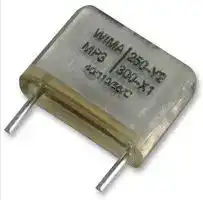
Illustrative purposes only

MPY20W2220FE00MSSD
Safety Capacitor, Metallized Paper, Radial Box - 2 Pin, 0.022 µF, ± 20%, Y2, Through Hole
⚠️ Reference pricing provided. In case of supply shortages, we will connect you with our trusted procurement partners to ensure your project's continuity.
- Manufacturer: WIMA
- Product type: Noise Suppression & Safety Capacitors
- SVHC: No SVHC (27-Jun-2018)
- Capacitance: 0.022µF
- Lead Spacing: 15mm
- dv/dt Rating: 1.75kV/µs
- Product Range: MPY2 Series
- Qualification: -
- Dielectric Type: Metallized Paper
- Humidity Rating: -
- Voltage Rating X: -
- Voltage Rating Y: 250VAC
- Suppression Class: Y2
- Capacitor Mounting: Through Hole
- Capacitance Tolerance: ± 20%
- Capacitor Case / Package: Radial Box - 2 Pin
- Operating Temperature Max: 110°C
- Operating Temperature Min: -40°C
| Delivery and price | |
|---|---|
| Units per pack | 500 |
| Price | 0.747 € |
| Current stock | 500+ |
| Lead time | 7 days |
Datasheet

## ~~WIMA MP 3-Y2 / 3R-Y2~~ <> D Metallized Paper (MP) RFI-Capacitors Class Y2 in PCM 10 mm to 27.5 mm. Capacitances from 1000 pF to 0.1 mF. Rated Voltages 250 VAC and 300 VAC. ## Special Features ## Electrical Data - ˜ Particularly high reliability against active and passive flammability Capacitance range: Maximum pulse rise time 250 VAC: 1000 pF to 0.1 mF (E12-values on request) Capacitance Pulse rise time V/msec Rated voltages: pF/mF max. operation 250 VAC, 300 VAC 1000 ... 4700 2500 Continuous DC voltage* (general guide): 6800 ... 0.022 1750 250 VAC: 1000 V ~~=~~ 300 VAC: 1250 V Maximum pulse rise time 300 VAC: Capacitance tolerances: ±20% Operating temperature range: –40) C to +110) C Capacitance pF/mF Pulse rise time V/max. operationmsec Climatic test category: 1000 ... 4700 2500 250 VAC: 40/110/56/C 6800 ... 0.015 1850 300 VAC: 40/110/56/B 0.022 ... 0.1 600 in accordance with IEC for pulses equal to a voltage amplitude Insulation resistance at +20+ C: ~~—t—~~ with 2 x 250 VAC = 355 V 12 x 10[3] M¸ with 2 x 300 VAC = 425 V - ˜ Excellent self-healing as well as high voltage strength - ˜ Twice the safety by internal series connection (300 VAC) - ˜ High degree of interference suppression due to good attenuation and low ESR - ˜ For temperatures up to +110° C - ˜ According to RoHS 2011/65/EU ## ~~Typical Applications~~ Class Y2 RFI applications to meet EMC regulations Measuring voltage: 100 V/1 min. Dissipation factors: according to IEC 60384-14 Test voltage: 2400 VDC, 2sec. Reliability: - ˜ Capacitors connected to the mains between phase or neutral and earthed casing earthed casing tan d 13 x 10[–3] at 1 kHz and +20+ C Reliability: ˜ By-passing of the basic or supplementary insulation, Test specifications:in accordance with IEC 60384-14 Failure rate Operational life 1 fit (0.5 x U 300 000 hours r and 40) C) pulse peak voltage 5 kV Approvals: Authority Specification Symbol Approval-No. ~~Construction~~ UL/Demko EN 60384-14 ENEC-02833 (250 VAC) **5** ENEC-02399 (300 VAC) Dielectric: UL UL 60384-14 E 100438 Paper, epoxy resin impregnated CAN/CSA-E60384-14 Capacitor electrodes: ~~Tf (ep~~ Vacuum-deposited Internal construction: 250 VAC ~~Mechanical Tests Packing~~ Capacitor paper Pull test on pins: 10 N in direction of pins Available taped and reeled. Vacuum-deposited electrode according to IEC 60068-2-21 Metal contact layer(schoopage)(schoopage) Vibration: 6 hours at 10 ... 2000 Hz and Detailed taping information and graphs Terminating wire 0.75 mm displacement amplitude or 10 g at the end of the catalogue. in accordance with IEC 60068-2-6 **==> picture [139 x 154] intentionally omitted <==** **----- Start of picture text -----**<br> 250 VAC<br>Capacitor paper<br>Vacuum-deposited<br>electrode<br>Metal contact layer(schoopage)(schoopage)<br>Terminating wire<br>300 VAC<br>Capacitor paper<br>Vacuum-deposited<br>electrode<br>Metal contact layer<br>(schoopage)<br>Terminating wire<br>**----- End of picture text -----**<br> Low air density: 1kPa = 10 mbar in accordance with IEC 60068-2-13 Bump test: 4000 bumps at 390 m/sec[2] in accordance with IEC 60068-2-29 For further details and graphs please refer to Technical Information. * If safety-approved EMI suppression capacitors are operated with a DC voltage being above the specified AC voltage rating the given approvals are no longer valid (IEC 60384-14). Furthermore the permissible pulse rise time du/dt (Fmax.) will be subject to a reduction according to Encapsulation: Self-extinguishing epoxy resin, UL 94 V-0. metal foil Terminations: Fmax. = Fr x 2 x UAC / UDC Tinned wire. Marking: Marking: Black on Silver. if the DC operating voltage UDC is higher than 2 x UAC 94 D ## ~~WIMA MP 3-Y2 / 3R-Y2~~ ## Continuation ## General Data **==> picture [488 x 597] intentionally omitted <==** **----- Start of picture text -----**<br> 250 VAC* 300 VAC*<br>Capacitance<br>W H L PCM** Part number W H L PCM** Part number<br>1000 pF 4 8.5 13.5 10 MPY20W1100FA00_ _ _ _ 5 13 19 15 MPRY2W1100FC00_ _ _ _<br>1500 „ 4 8.5 13.5 10 MPY20W1150FA00_ _ _ _ 5 13 19 15 MPRY2W1150FC00_ _ _ _<br>2200 „ 4 8.5 13.5 10 MPY20W1220FA00_ _ _ _ 5 13 19 15 MPRY2W1220FC00_ _ _ _<br>3300 „ 4 8.5 13.5 10 MPY20W1330FA00_ _ _ _ 5 13 19 15 MPRY2W1330FC00_ _ _ _<br>4700 „ 5 10 13.5 10 MPY20W1470FB00_ _ _ _ 6 14 19 15 MPRY2W1470FD00_ _ _ _<br>6800 „ 5 13 19 15 MPY20W1680FC00_ _ _ _ 7 15 19 15 MPRY2W1680FE00_ _ _ _<br>0.01 mF 5 13 19 15 MPY20W2100FC00_ _ _ _ 8 17 19 15 MPRY2W2100FF00_ _ _ _<br>0.015 „ 6 14 19 15 MPY20W2150FD00_ _ _ _ 10 18 19 15 MPRY2W2150FG00_ _ _ _<br>0.022 „ 7 15 19 15 MPY20W2220FE00_ _ _ _ 8 20 28 22.5 MPRY2W2220FH00_ _ _ _<br>0.033 „ 8 20 28 22.5 MPRY2W2330FH00_ _ _ _<br>0.047 „ 10 22 28 22.5 MPRY2W2470FI00_ _ _ _<br>0.068 „ 12 24 28 22.5 MPRY2W2680FJ00_ _ _ _<br>0.1 mF 13 25 33 27.5 MPRY2W3100FK00_ _ _ _<br>* f = 50/60 Hz 10<br>** PCM = Printed circuit module = pin spacing Z<br>�<br>Upon request with long pins 35-2 mm max. 1<br>7<br>5<br>Dims. in mm. 3<br>W L<br>0.1<br>7<br>5<br>3 250 VAC<br>H<br>d = 0.6 P if PCM 10<br>d = 0.8 P if PCM 15 0.01 1 3 5 7 10 3 5 7 100 1000<br>f/MHz<br>6 -2 Impedance change with frequency<br>d PCM (general guide)<br>at the pin exit<br>points 10<br>(± 0.5)<br>Z 300 VAC<br>�<br>1<br>7<br>5<br> Part number completion: 3<br> Tolerance: 20 % = M<br> Packing: bulk = S 0.17<br> Pin length: 6-2 = SD 5<br> Taped version see page 149. 3<br>0.01<br>1 3 5 7 10 3 5 7 100 1000<br>f/MHz<br>Impedance change with frequency<br>Rights reserved to amend design data without prior notification. (general guide)<br>--<br>--<br>-- --4700--3300220015001000pFpFpFpF<br>pF PCM 10<br>6800<br>pF<br>--<br>--<br>--<br>-- 0.01<br>0.015 µF<br>0.022 µF<br>µF PCM15<br>--<br>--<br>--<br>0.1 µF -- -- -- -- -- -- -- --0,01--6800--47003300pF2200pF15001000pFpFpF<br>pF<br>0.033 µF0.022 µF0,015 µFµF<br>0.047 µF<br>0.068 µF<br>**----- End of picture text -----**<br> 95 D ## Recommendation for Processing and Application of Through-Hole Capacitors ## ~~Soldering Process~~ Internal temperature of the capacitor must be kept as follows: Polyester: preheating: Tmax. 125° C soldering: Tmax. 135° C Polypropylene: preheating: Tmax. 100° C soldering: Tmax. 110° C Single wave soldering Soldering bath temperature: T 260 ° C Dwell time: t 5 sec Double wave soldering Soldering bath temperature: T 260 ° C Dwell time: St 5 sec Due to different soldering processes and heat requirements the graphs are to be regarded as a recommendation only. ## ~~WIMA Quality and Environmental Philosophy~~ ## ~~ISO 9001:2015 Certification~~ ISO 9001:2015 is an international basic standard of quality assurance systems for all branches of industry. The approval according to ISO 9001:2015 of our factories by the infaz (Institut für Auditierung und Zertifizierung) certifies that organisation, equipment and monitoring of quality assurance in our factories correspond to internationally recognized standards. ## ~~WIMA WPCS~~ The WIMA Process Control System (WPCS) is a quality surveillance and optimization system developed by WIMA. WPCS is a major part of the quality-oriented WIMA production. Points of application during production process: - ” incoming material inspection ## ~~WIMA Environmental Policy~~ All WIMA capacitors, irrespective of whether through-hole devices or SMD, are made of environmentally friendly materials. Neither during manufacture nor in the product itself any toxic substances are used, e.g. – Lead – PBB/PBDE – PCB – Arsenic – CFC – Cadmium – Hydrocarbon chloride – Mercury – Chromium 6+ – etc. We merely use pure, recyclable materials for packing our components, such as: - ” carton - ” cardboard - ” adhesive tape made of paper - ” polystyrene ## ~~RoHS Compliance~~ According to the RoHS Directive 2011/65/EU as amended from time to time certain hazardous substances like e.g. lead, cadmium, mercury must not be used any longer in electronic equipment as of July 1st, 2006. For the sake of the environment WIMA has refraind from using such substances since years already. **WIMA Kondensatoren sind bleifrei konform RoHS 2011/65/EU WIMA capacitors are lead free in accordance with RoHS 2011/65/EU** Tape for lead-free WIMA capacitors - ” metallization - ” film inspection - ” schoopage - ” pre-healing - ” pin attachment - ” cast resin preparation/ encapsulation - ” 100% final inspection - ” Testing as per customer requirements We almost completely refrain from using packing materials such as: - ” adhesive tapes made of plastic - ” metal clips ## ~~DIN EN ISO 14001:2004~~ WIMA’s environmental management has been established in accordance with the guidelines of DIN EN ISO 14001:2004 to optimize the production processes with regard to energy and resources. 15 Typical Dimensions for Taping Configuration **==> picture [92 x 52] intentionally omitted <==** **----- Start of picture text -----**<br> D<br>**----- End of picture text -----**<br> |D<br>Til Dii f|D<br>Til Dii f|D<br>Til Dii f|D<br>Til Dii f|D<br>Til Dii f|D<br>Til Dii f|D<br>Til Dii f|D<br>Til Dii f|D<br>Til Dii f|D<br>Til Dii f|D<br>Til Dii f|D<br>Til Dii f|D<br>Til Dii f|D<br>Til Dii f|D<br>Til Dii f|D<br>Til Dii f|D<br>Til Dii f|D<br>Til Dii f|D<br>Til Dii f|D<br>Til Dii f|D<br>Til Dii f|D<br>Til Dii f|D<br>Til Dii f|D<br>Til Dii f| |---|---|---|---|---|---|---|---|---|---|---|---|---|---|---|---|---|---|---|---|---|---|---|---| |ypca mensons or<br>Taping Configuration|||||||||||||||||||||||| |W0<br>H1<br>H<br>Diagram 2: PCM 10/15 m||||||P2<br>|||||P||||W2<br>W1<br>W|t<br>Vh|||||||| ||||||||||||||||||||||||| ||||H1||||||||||||||||||||| |||||W0<br>H||P1|||||||||||||||||| ||||||||||||||||||||||||| ||||||||||||||||||||||||| ||||||||||||||D0||||||||||| ||||||||||||||||||||||||| |||||||P<br>P1<br>P0<br>F|||||||d||||||||||| ||||||||||||||||||||||||| ||||||||||||||||||||||||| ||||||||||||||||||||||||| ||||||||||||||||||||||||| ||||||||||||||||||||||||| ||||||||||||||||||||||||| ||||||||||d||||||||||||d||| ||||||F<br>m||||P<br>P||0<br>2||||||||||||| ||||||||||||||||||||||||| |Designation|Symbol|PCM 2.5 taping<br>PCM 5 taping||||||||||||Dimensions for Radial Taping<br>PCM 7.5 taping<br>PCM 10 taping*<br>PCM 15 taping*<br>PCM 22.5 taping<br>PCM 27.5 taping|||||||||| |Carrier tape width|W|18.0p0.5||||||18.0p0.5||||||18.0p0.5|||18.0p0.5||18.0p0.5|||18.0p0.5|18.0p0.5| |Hold-down tape width|W0|6.0for hot-sealing<br>adhesive tape||||||6.0for hot-sealing<br>adhesive tape||||||12.0for hot-sealing<br>adhesive tape|||12.0for hot-sealing<br>adhesive tape||12.0for hot-sealing<br>adhesive tape|||12.0for hot-sealing<br>adhesive tape|12.0for hot-sealing<br>adhesive tape| |Hole position|W1|9.0p0.5||||||9.0p0.5||||||9.0p0.5|||9.0p0.5||9.0p0.5|||9.0p0.5|9.0p0.5| |Hold-down tape position|W2|0.5 to 3.0 max.||||||0.5 to 3.0 max.||||||0.5 to 3.0 max.|||0.5 to 3.0 max.||0.5 to 3.0 max.|||0.5 to 3.0 max.|0.5 to 3.0 max.| |Feed hole diameter|D0|4.0p0.2||||||4.0p0.2||||||4.0p0.2|||4.0p0.2||4.0p0.2|||4.0p0.2|4.0p0.2| |Pitch of component|P|12.7p1.0||||||12.7p1.0||||||12.7p1.0|||25.4p1.0||25.4p1.0|||38.1p1.5|3*8.1p1.5or 50.8p1.5| |Feed hole pitch<br>|P0|cumulative pitch<br>12.7p0.3 error max.<br> 1.0 mm/20 pitch||||||cumulative pitch<br>12.7p0.3 error max.<br> <br> 1.0 mm/20 pitc||||||<br> cumulative pitc<br>12.7p0.3 error max.<br>h<br> 1.0 mm/20 pitc|||h<br> cumulative pitch<br>12.7p0.3 error max.<br>h<br> 1.0 mm/20 pitch||<br> cumulative pitch<br>12.7p0.3 error max.<br> <br> 1.0 mm/20 pitch|||cumulative pitch<br>12.7p0.3 error max.<br> 1.0 mm/20 pitch|cumulative pitch<br>12.7p0.3 error max.<br> 1.0 mm/20 pitch| |~~d hl~~|||||||||||||||||||||||| |~~Fee oe centre~~<br>to pin|P1|5.1p0.5||||||3.85p0.7||||||2.6p0.7|||7.7p0.7||5.2p0.7|||7.8p0.7|5.3p0.7| |Hole centre to<br>component centre|P2|6.35p1.3||||||6.35p1.3||||||6.35p1.3|||12.7p1.3||12.7p1.3|||19.05p1.3|19.05p1.3| |Feed hole centre to bottom<br>edge of the component|H|16.5p0.3||||||16.5p0.3||||||16.5p0.5|||16.5p0.5||16.5p0.5|||16.5p0.5|16.5p0.5| |||18.5p0.5||||||18.5p0.5||||||18.5p0.5|||18.5p0.5||18.5p0.5|||18.5p0.5|18.5p0.5| |Feed hole centre to top<br>edge of the component|H1|H+Hcomponent< H1<br>32.25 max.||||||H+Hcomponent< H1<br>32.25 max.||||||H+Hcomponent< H1<br>24.5 to 31.5|||H+Hcomponent< H1<br>25.0 to 31.5||H+Hcomponent< H1<br>26.0 to 37.0|||H+Hcomponent< H1<br>30.0 to 43.0|H+Hcomponent< H1<br>35.0 to 45.0| |Pin spacing at<br>upper edge of carrier tape|F|2.5p0.5||||||5.0<br>+0.8<br> –0.2||||||7.5p0.8|||10.0p0.8||15p0.8|||22.5p0.8|27.5p0.8| |Pin diameter|d|0.4p0.05||||||0.5p0.05||||||„0.5p0.05 or0.6–0.05<br>+0.06|||„0.5p0.05 or0.6–0.05<br>+0,06||0.8–0.05<br>+0,08|||0.8–0.05<br>+0,08|0.8–0.05<br>+0.08| |Component alignment|Dh|p2.0 max.||||||p2.0 max.||||||p3.0 max.|||p3.0 max.||p3.0 max.|||p3.0 max.|p3.0 max.| |Total tape thickness|t|0.6p0.2||||||0.6p0.2||||||0.6p0.2|||0.6p0.2||0.6p0.2|||0.6p0.2|0.6p0.2| |Package<br>(see also page 150)||ROLL/AMMO||||||||||||AMMO|||||||||| |||REEL P360 max.<br>B 52p2 depending on<br>P30p1<br>58p2 comp. dimension||||||||||||s<br>52p2<br>54p2 depending<br> REELP360 max.<br>B 58p2 orREEL<br>P500 max.<br>B 60p2 on PCM and<br>P30p1<br>66p2<br>P25p1<br>68p2 component dimensions|||||||||| |Unit||||||||||||||see details page 151.|||||||||| |Dims in mm.<br>„Diameter of pins see General Data.<br>Please clarify customer-specific deviations with the manufacturer.<br> *PCM 10 and PCM 15 can be crimped to PCM 7.5.<br>Position of components according to PCM 7.5 (sketch 1). P0= 12.7 or 15.0 is possible|||||||||||||||||||||||| Dims in mm. „ Diameter of pins see General Data. Please clarify customer-specific deviations with the manufacturer. * PCM 10 and PCM 15 can be crimped to PCM 7.5. Position of components according to PCM 7.5 (sketch 1). P0 = 12.7 or 15.0 is possible 149 D ## Types of Tape Packaging of Capacitors for Automatic Radial Insertion **==> picture [83 x 11] intentionally omitted <==** **----- Start of picture text -----**<br> ˜ ROLL Packaging<br>**----- End of picture text -----**<br> **==> picture [421 x 208] intentionally omitted <==** **----- Start of picture text -----**<br> ˜ AMMO Packaging ˜ REEL Packaging<br>3<br>eg Se<br>eg SF = ———<br>: Rey<br>leg Qe eS<br>e eg SESE<br><Ss |o SIEmt SSE<br>30±1<br>25±1<br>50 max.<br>50 max. 70 max. B<br>340 max. 340 max.<br>490 max.<br>340 max. 370 max.<br>340 max.<br>360 max. 500 max.<br>**----- End of picture text -----**<br> ## ~~BAR CODE (Labelling)~~ Labelling of package units in plain text and with alphanumerical Bar Code BARCODE „Code 39” Scanner decoding of - „ WIMA supplier number - „ Customer‘s P/O number - „ Customer‘s part number - „ WIMA confirmation number - „ WIMA part number - „ Lot number - „ Date code - „ Quantity In addition part description of - article - capacitance value - rated voltage - dimensions - capacitance tolerance - packing as well as gross weight and customer‘s name are indicated in plain text. 150 D Packing Quantities for Capacitors with Radial Pins in PCM 2.5 mm to 22.5 mm **==> picture [489 x 616] intentionally omitted <==** **----- Start of picture text -----**<br> pcs. per packing unit<br>ROLL REEL AMMO<br>Size<br>PCM bulk P 360 P 500 340 [x] 340 490 [x] 370<br>H16.5 H18.5 H16.5 H18.5 H16.5 H18.5 H16.5 H18.5 H16.5 H18.5<br>W H L Codes S N O F I H J A C B D<br> 2.5 7 4.6 0B 5000 2200 2500 – 2800 –<br> 3 7.5 4.6 0C 5000 2000 2300 – 2300 –<br>2.5 mm 3.8 8.5 4.6 0D 5000 1500 1800 – 1800 –<br> 4.6 9 4.6 0E 5000 1200 1500 – 1500 –<br> 5.5 10 4.6 0F 5000 900 1200 – 1200 –<br> 2.5 6.5 7.2 1A 5000 2200 2500 – 2800 –<br> 3 7.5 7.2 1B 5000 2000 2300 – 2300 –<br> 3.5 8.5 7.2 1C 5000 1600 2000 – 2000 –<br> 4.5 6 7.2 1D 6000 1300 1500 – 1500 –<br> 4.5 9.5 7.2 1E 4000 1300 1500 – 1500 –<br> 5 10 7.2 1F 3500 1100 1400 – 1400 –<br>5 mm 5.5 5.5 711.5 7.2 7.2 1G1H 40002500 10001000 12001200 –– 12001200 ––<br> 6.5 8 7.2 1I 2500 800 1000 – 1000 –<br> 7.2 8.5 7.2 1J 2500 700 1000 – 1000 –<br> 7.2 13 7.2 1K 2000 700 950 – 1000 –<br> 8.5 10 7.2 1L 2000 600 800 – 800 –<br> 8.5 14 7.2 1M 1500 600 800 – 800 –<br>11 16 7.2 1N 1000 500 600 – 640 –<br> 2.5 7 10 2A 5000 – 2500 4400 2500 –<br> 3 8.5 10 2B 5000 – 2200 4300 2300 4150<br> 4 9 10 2C 4000 – 1700 3200 1700 3100<br>7.5 mm 4.5 9.5 10.3 2D 3500 – 1500 2900 1400 2700<br> 5 10.5 10.3 2E 3000 – 1300 2500 1300 –<br> 5.7 12.5 10.3 2F 2000 – 1000 2200 1100 –<br>7.2 12.5 10.3 2G 1500 – 900 1800 1000 –<br> 3 9 13 3A 3000 – 1100 2200 – 1900<br> 4 8.5 13.5 FA 3000 – 900 1600 – 1450<br> 4 9 13 3C 3000 – 900 1600 – 1450<br> 4 9.5 13 3D 3000 – 900 1600 – 1400<br>10 mm 5 10 13.5 FB 2000 – 700 1300 – 1200<br> 5 11 13 3F 3000 – 700 1300 – 1200<br> 6 12 13 3G 2400 – 550 1100 – 1000<br> 6 12.5 13 3H 2400 – 550 1100 – 1000<br>8 12 13 3I 2000 – 400 800 – 740<br> 5 11 18 4B 2400 – 600 1200 – 1150<br> 5 13 19 FC 1000 – 600 1200 – 1200<br> 6 12.5 18 4C 2000 – 500 1000 – 1000<br> 6 14 19 FD 1000 – 500 1000 – 1000<br> 7 14 18 4D 1600 – 450 900 – 850<br> 7 15 19 FE 1000 – 450 900 – 850<br>15 mm 8 15 18 4F 1200 – 400 800 – 740<br> 8 17 19 FF 500 – 400 800 – 740<br> 9 14 18 4H 1200 – 350 700 – 650<br> 9 16 18 4J 900 – 350 700 – 650<br>10 18 19 FG 500 – 300 650 – 590<br>11 14 18 4M 1000 – 300 600 – 540<br> 5 14 26.5 5A 1200 – – 800 – 770<br> 6 15 26.5 5B 1000 – – 700 – 640<br> 7 16.5 26.5 5D 760 – – 600 – 550<br> 8 20 28 FH 500 – – 500 – 480<br>22.5 mm 8.510 18.522 26.528 5FFI 500570* –– –– 480 420 –– 450 380<br>10.5 19 26.5 5G 594* – – 400 – 360<br>10.5 20.5 26.5 5H 594* – – 400 – 360<br>11 21 26.5 5I 561* – – 380 – 350<br>12 24 28 FJ 480* – – 350 – 310<br>* TPS (Tray-Packing-System). Plate versions may have different packing units. Moulded versions. Rights reserved to amend design data without prior notification.<br> Samples and pre-production needs on request.<br>**----- End of picture text -----**<br> 151 D Packing Quantities for Capacitors with Radial Pins in PCM 27.5 mm to 52.5 mm **==> picture [490 x 357] intentionally omitted <==** **----- Start of picture text -----**<br> pcs. per packing unit<br>ROLL REEL AMMO<br>Size<br>PCM bulk P 360 P 500 340 [x] 340 490 [x] 370<br>H16.5 H18.5 H16.5 H18.5 H16.5 H18.5 H16.5 H18.5 H16.5 H18.5<br>W H L Codes S N O F I H J A C B D<br> 9 19 31.5 6A 567* – – 460/340* – 420<br>11 21 31.5 6B 459* – – 380/280* – 350<br>13 24 31.5 6D 378* – – 300 – 290<br>13 25 33 FK 405* – – – – –<br>27.5 mm 1515 2626 31.533 6FFL 324324** –– –– 270– –– 250–<br>17 29 31.5 6G 198* – – – – –<br>17 34.5 31.5 6I 198* – – – – –<br>20 32 33 FM 162* – – – – –<br>20 39.5 31.5 6J 162* – – – – –<br> 9 19 41.5 7A 441* – – – – –<br>11 22 41.5 7B 357* – – – – –<br>13 24 41.5 7C 294* – – – – –<br>15 26 41.5 7D 252* – – – – –<br>17 29 41.5 7E 154* – – – – –<br>37.5 mm 19 32 41.5 7F 140* – – – – –<br>20 39.5 41.5 7G 126* – – – – –<br>24 45.5 41.5 7H 112* – – – – –<br>31 46 41.5 7I 84* – – – – –<br>35 50 41.5 7J 35* – – – – –<br>40 55 41.5 7K 28* – – – – –<br>19 31 56 8D 120* – – – – –<br>23 34 56 8E 80* – – – – –<br>48.5 mm 27 37.5 56 8H 84* – – – – –<br>33 48 56 8J 25* – – – – –<br>37 54 56 8L 25* – – – – –<br>25 45 57 9D 70* – – – – –<br>30 45 57 9E 60*<br>52.5 mm 35 50 57 9F 25*<br>45 55 57 9H 20* – – – – –<br>45 65 57 9J 20* – – – – –<br>**----- End of picture text -----**<br> * for 2-inch transport pitches. Moulded versions. Rights reserved to amend design data without prior notification. * TPS (Tray-Packing-System). Plate versions may have different packing units. Samples and pre-production needs on request. Updated data on www.wima.com 152 D WIMA Part Number System A WIMA part number consists of 18 digits and is composed as follows: **==> picture [489 x 138] intentionally omitted <==** **----- Start of picture text -----**<br> Field 1 - 4: Type description<br>Field 5 - 6: Rated voltage<br>Field 7 - 10: Capacitance<br>Field 11 - 12: Size and PCM<br>Field 13 - 14: Version code (e.g. Snubber versions)<br>Field 15: Capacitance tolerance<br>Field 16: Packing<br>Field 17 - 18: Pin length (untaped)<br>1 2 3 4 5 6 7 8 9 10 11 12 13 14 15 16 17 18<br>M K S 2 C 0 2 1 0 0 1 A 0 0 M S S D<br>**----- End of picture text -----**<br> |MKS 2|MKS 2|MKS 2|63 VDC|63 VDC|63 VDC||0.01mF|0.01mF|0.01mF|2.5 x 6.5 x 7.2||-|-||20 %<br>bulk|||6|-2| |---|---|---|---|---|---|---|---|---|---|---|---|---|---|---|---|---|---|---|---| ||||||||||||||||||||| |Type description:|||Rated voltage:||||Capacitance:|||Size:|||||Tolerance:||||| |SMD-PET||= SMDT|50 VDC||= B0||22 pF|= 0022||4.8 x 3.3 x 3 Size 1812||= KA|||±20 %<br>= M||||| |SMD-PEN||= SMDN|63 VDC||= C0||47 pF|= 0047||4.8 x 3.3 x 4 Size 1812||= KB|||±10 %<br>= K||||| |SMD-PPS||= SMDI|100 VDC||= D0||100 pF|= 0100||5.7 x 5.1 x 3.5 Size 2220||= QA|||±5 %<br>= J||||| |FKP 02||= FKP0|250 VDC||= F0||150 pF|= 0150||5.7 x 5.1 x 4.5 Size 2220||= QB|||±2.5 %<br>= H||||| |MKS 02||= MKS0|400 VDC||= G0||220 pF|= 0220||7.2 x 6.1 x 3 Size 2824||= TA|||±1 %<br>= E||||| |FKS 2||= FKS2|450 VDC||= H0||330 pF|= 0330||7.2 x 6.1 x 5 Size 2824||= TB|||...||||| |FKP 2||= FKP2|520 VDC||= H2||470 pF|= 0470||10.2 x 7.6 x 5 Size 4030||= VA|||||||| |FKS 3<br>FKP 3||= FKS3<br>= FKP 3|600 VDC<br>630 VDC||= I0<br>= J0||680 pF<br>1000 pF|= 0680<br> = 1100||12.7 x 10.2 x 6 Size 5040 <br>15.3 x 13.7 x 7 Size 6054||= XA<br> = YA|||Packing:||||| |MKS 2||= MKS2|700 VDC||= K0||1500 pF|= 1150||2.5 x 7 x 4.6 PCM 2.5||= 0B|||AMMO H16.5 340 x 340 = A||||| |MKP 2||= MKP2|800 VDC||= L0||2200 pF|= 1220||3 x 7.5 x 4.6 PCM 2.5||= 0C|||AMMO H16.5 490 x 370 = B||||| |MKS 4||= MKS4|850 VDC||= M0||3300 pF|= 1330||2.5 x 6.5 x 7.2 PCM 5||= 1A|||AMMO H18.5 340 x 340 = C||||| |MKP 4C||= MKPC|900 VDC||= N0||4700 pF|= 1470||3 x 7.5 x 7.2 PCM 5||= 1B|||AMMO H18.5 490 x 370 = D||||| |MKP 4||= MKP4|1000 VDC||= O1||6800 pF|= 1680||2.5 x 7 x 10 PCM 7.5||= 2A|||REEL H16.5 360||||= F| |MKP 10||= MKP1|1100 VDC||= P0||0.01mF|= 2100||3 x 8.5 x 10 PCM 7.5||= 2B|||REEL H16.5 500||||= H| |FKP 1||= FKP1|1200 VDC||= Q0||0.022mF|= 2220||3 x 9 x 13 PCM 10||= 3A|||REEL H18.5 360||||= I| |MKP-X2||= MKX2|1250 VDC||= R0||0.047mF|= 2470||4 x 9 x 13 PCM 10||= 3C|||REEL H18.5 500||||= J| |MKP-X1 R||= MKX1|1500 VDC||= S0||0.1mF|= 3100||5 x 11 x 18 PCM 15||= 4B|||ROLL H16.5||||= N| |MKP-Y2||= MKY2|1600 VDC||= T0||0.22mF|= 3220||6 x 12.5 x 18 PCM 15||= 4C|||ROLL H18.5||||= O| |MP 3-X2||= MPX2|2000 VDC||= U0||0.47mF|= 3470||5 x 14 x 26.5 PCM 22.5||= 5A|||BLISTER W12 180||||= P| |MP 3-X1||= MPX1|2500 VDC||= V0||1mF|= 4100||6 x 15 x 26.5 PCM 22.5||= 5B|||BLISTER W12 330||||= Q| |MP 3-Y2||= MPY2|3000 VDC||= W0||2.2mF|= 4220||9 x 19 x 31.5 PCM 27.5||= 6A|||BLISTER W16 330||||= R| |MP 3R-Y2||= MPRY|4000 VDC||= X0||4.7mF|= 4470||11 x21 x 31.5 PCM 27.5||= 6B|||BLISTER W24 330||||= T| |MKP 4F||= MKPF|6000 VDC||= Y0||10mF|= 5100||9 x 19 x 41.5 PCM 37.5||= 7A|||Bulk/TPS Standard||||= S| |Snubber MKP||= SNMP|250 VAC||= 0W||22mF|= 5220||11 x 22 x 41.5 PCM 37.5||= 7B|||...||||| |Snubber FKP||= SNFP|275 VAC||= 1W||47mF|= 5470||19 x 31 x 56 PCM 48.5||= 8D|||||||| |GTO MKP||= GTOM|300 VAC||= 2W||100mF|= 6100||25 x 45 x 57 PCM 52.5||= 9D|||||||| |DC-LINK MKP|3|= DCP3|305 VAC||= AW||220mF|= 6220||...|||||||||| |DC-LINK MKP|4|= DCP4|350 VAC||= BW||1000mF|= 7100|||||||||||| |DC-LINK MKP 4S <br>DC-LINK MKP 5||= DCPS<br> = DCP5|440 VAC<br>500 VAC||= 4W<br>= 5W||1500mF <br>...|= 7150||Version code:|||||Pin length (untaped)||||| |DC-LINK MKP|6|= DCP6|...|||||||Standard<br>= 00|||||3.5 ±0.5 = C9||||| |DC-LINK HC||= DCHC||||||||Version A1<br>= 1A|||||6 -2<br>= SD||||| |DC-LINK HY||= DCHY||||||||Version A1.1.1 = 1B|||||16 ±1<br>= P1||||| |||||||||||Version A2<br>= 2A|||||...||||| |||||||||||...|||||Pin length (taped)||||| ||||||||||||||||none<br>= 00||||| The data on this page is not complete and serves only to explain the part number system. Part number information is listed on the pages of the respective WIMA range. 147
Updated at March 21, 2026
About Novapart
Novapart is a B2B electronic component broker specialising in stock shortages and cost reduction. We source hard-to-find parts and identify compliant alternatives across a catalogue of 410,000+ components from 500+ manufacturers.
Learn more →Stock Shortage Specialist
When a component is unavailable, discontinued or has an unacceptable lead time, we tap into our network of vetted European and Asian distributors to source what you need — without compromising on quality or traceability.
Request a quote →Compliant Alternatives
We identify pin-to-pin, electrically equivalent substitutes that meet the same certifications (RoHS, AEC-Q100, REACH) as your original specification — validated against datasheets, not just part numbers. Often at a lower cost.
BOM Analysis service →