
Image not available
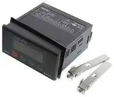
Illustrative purposes only

MP5W-4N
DIGITAL PULSE METER, 5-DIGIT, 100VAC TO
⚠️ Reference pricing provided. In case of supply shortages, we will connect you with our trusted procurement partners to ensure your project's continuity.
- Manufacturer: AUTONICS
- Product type: Digital Panel Meters
- DIGITAL PULSE METER, 5-DIGIT, 100VAC TO 240VAC; No. of Digits / Alpha:5; Meter Function:Pulse; Meter Range:-; Digit Height:13.8mm; Panel Cutout Height:46mm; Panel Cutout Width:92m
- Meter Range: -
- Digit Height: 13.8mm
- Product Range: MP5W Series
- Meter Function: Pulse
- Panel Cutout Width: 92mm
- Supply Voltage Max: 240VAC
- Supply Voltage Min: 100VAC
- Panel Cutout Height: 46mm
- No. of Digits / Alpha: 5
- Operating Temperature Max: 50°C
- Operating Temperature Min: -10°C
| Delivery and price | |
|---|---|
| Units per pack | 1 |
| Price | 122.84 € |
| Current stock | 10+ |
| Lead time | 30 days |
Datasheet

MP5S/MP5Y/MP5W/MP5M Seriesa

## ~~I~~

**==> picture [501 x 728] intentionally omitted <==**

**----- Start of picture text -----**<br>
(=|Features<br>@13 kinds of various operation modes :<br>Revolution, speed, frequency, absolute ratio, passing time,<br>error ratio, cycle, density, passing speed, error,<br>time width, length measurement, time difference, interval, ne<br>multiplication(MP5M Series have 11 operation modes) =<br>@Various output function : ——_ —aay_ | ooae333599<br>Relaylow speedoutput,serial NPN/PNPoutput, openBCD output,collector output, a = _$9999 , |t=ccd :<br>PV transmission, RS485 communication output<br>: a a sae I Le<br>@Various functions : aay a<br>Prescalefunction, peakfunction,valuedatamonitoringmonitoringfunction,function,monitoringhysteresis -coe<br>delay function, auto zero time setting function, - +2<br>lock setting function, display period delay function ms<br>@Max. display range : -19999 to 99999 (MP5M : 0 to 99999)<br>@Various display units : rpm, rps, Hz, kHz, sec, min, m, mm, mm/s, m/s,<br>m/min, m/h, ’/s, 2/min, ¢/h, %, counts, etc.<br>@Selectable voltage input(PNP) or no voltage input (NPN)<br>@50kHz high speed response<br>operation [manualbefore] [using.] CAli: US C E<br>@™Ordering information<br>mp] [5] [s]- [4] Ly)<br>S type ;<br>Output<br>W type<br>F6 [NPN open collector quintuple output| Low speed serial output ——_|<br>Po: [NPN oper collector quintuple output RS485 communication output<br>| 9 [PNP open collector quintuple output | RS485 communication output _|<br>M type + NPN open collector output<br>Relay dual(High/Low-limit) output<br>Power supply (x1)<br>% (* 1) Low voltage type is only for MP4S, MP5Y, MP5W Series.<br>Size<br>Digit<br>Series<br>3%*PNP open collector output : Option7<br>reer rere e eee e cece e ener eee eee ee eee eee ee eee ee eee<br>M-5 Autonics<br>**----- End of picture text -----**<br>


**==> picture [554 x 753] intentionally omitted <==**

**----- Start of picture text -----**<br>
a<br>i=) [Specifications(MP5S/MP5Y/MP5W] [Series)]<br>[Series [«dS] =a SY=9 |Y-a [PSO<br>Display method 7 Segment LED display (Zero blanking type) | wIPSWHa<br>Wa x H8mm W6.8 x H13.8mm<br>“THT<br>to 9050<br>= 100-240VAC 100-240VAC<br>100-—240VAC 50/60Hz 12VDC 50/60Hz 12VDC 50/60Hz<br>Ouiege operation Allowable operation voltage : 90 to 110%<br>Max, T5VA Max, TWA Max. BVA<br>[2VDC = 10%, SOmA<br>I nput tf ¢ Soild—state input : Max. 50kHz (Pulse width : Each over 10ys)<br>trequency * Contact input : Max. 45Hz(Pulse width : Over 11ms)<br>[Voltage input] High : 4.5-24VDC, Low : 0-1.0VDC, Input impedance : 4.5kQ<br>Input level [No-voltage input] Impedance at short-circuit : Max. 300, Residual voltage : Max. 1V<br>Impedance at open-circuit : Min. 100k 2<br>M easuring. * Mode F1, F2, F7, F8, F9, F10 : 0.0005Hz to 50kHz * Mode F3 : 0.02s to 3,200s<br>range * Mode F4, F5, F6 : 0.01s to 3,200s * Mode F11, F12, F13 : 0 to 4 X10" Count<br>Measuring accuracy * Mode F1, F2, F7, F8, F9, F10: F.S. 0.05% rdg +1Digit<br>(23 +5) * Mode F3, F4, F5, F6 > F.S. 0.01% rdg +1Digit<br>Display period 0.05/0.5/1/2/4/ 8sec.(It is same with period of output update.)<br>Number of revolution/Speed/Frequency (F1), Passing speed(F2), Cycle(F3), Passing time (F4),<br>0 ti d Time width(F5), Time defference(F6), Absolute ratio(F7), Error ratio(F8), Density (F9), Error (F10),<br>peration mode Length measurement (F11), Interval(F12), Multiplication (F13)<br>* Refer to M-19 to 22 for the operation mode.<br>Prescale function Direct input method (0.0001 x 10° to 9.9999 x 10° )<br>Hysteresis (Note1) 0 to 9999<br>* Lock setting function<br>* Monitoring delay function<br>. . *« Auto—zero time setting function<br>* Lock setting function .<br>* Auto—Z ti ttine functi * Current output range selection(Current output type only)<br>Au ow eero Time setting TUnCcuoOny Comparative output function(HH, H, GO, L, LL)<br>Other functions: ¢* PeakTime valueunit selectionmonitoringfunctionfunction * —Time unit. selection: function.<br>. . ¢ Deviation memory function(F output mode applied only)<br>* Memory protection function + Peak val itoring f ti<br>(Mode F13 applied only) eak value monitoring function a<br>* Remote/Local switching function(Communication output type only)<br>* Data bank switching function (Note2)<br>¢* Memory protection function(Mode F13 applied only)<br>250VAC 3A resistive load 3 Tac<br>2|NPN< | (Quintuple). Open collector ; poPulsemeter<br>‘Sss|PNP Open collector 12-—24VDC 30mA Max. 12-24VDC 20mA Max.<br>(Quintuple)<br>. NPN Open collector<br>2 : Sd 12-24VDC 20mA Max.<br>SlLow speedseraloupa<br>To) ei DC4-—20mA Load 6002 Max. ee<br>RS485 communication fC FT 32 channels, Mutual direction communication function<br>Non-volatile memory (Input : Min. 100,000 times)<br>Min. 1OOM®& (at 500VDC megger) Between charge part and non—charge part<br>Dielectric st th 2000VAC 60Hz Iminute (Between terminals of AC power and case,<br>lelectric steng Between terminals of AC power and measuring input terminals)<br>+2000VAC the square wave noise (pulse width : lus)by the noise simulator, repeat frequency 60Hz<br>0.75mm amplitude at frequency of 10 ~55Hz in each of X, Y, Z directions for 2 hour<br>Vibrationi i<br>0.5mm amplitude at frequency of 10 to 55Hz in each of X, Y, Z directions for 10 minutes<br>300m/s? (30G) in X, Y, Z directions for 3 times<br>Shockoc - 7 ; , ; 7<br>Relay [Malfunction| 100m/s’ (10G) in X, Y, Z directions Min, 10,000,000 for 3 times tines<br>life cycle} Mechanical | == S ——— ——s”7/ Min. 100,000 times (250VAC 3A load current)<br>—10 to 50 (at non-freezing status)<br>—20 to 60C (at non-freezing status)<br>Ambient humidity 35 to 85%RH<br>Approval =| CE As | CCE As | | CE As<br>Approx. 130g Approx. 135g Approx. 230g<br>x (Note1) The hysteresis setting range is changed by the setting position of decimal point. (Refer to M—25 for hysteresis function.)<br>%* (Note2) Data bank switching function is in MP5W series only.<br>rereeee eee reneerenee ener Autonicse M-6<br>**----- End of picture text -----**<br>


**==> picture [509 x 775] intentionally omitted <==**

**----- Start of picture text -----**<br>
MP5S/MP5Y/MP5W/MP5M Series<br>OO——————————————————eeeeeeererererererer—C=‘“E<br>l|Specifications(MP5M Series)<br>Model High—limit setting type High/Low-—limit setting type<br>Display method 7 Segment LED display (Zero blanking), Character size : W4 X H8mm<br>0.0001 to 99999<br>100-240VAC 50/60Hz<br>Allowable operation . .<br>Allowable operation voltage: 90 to 110%<br>Approx. 7.5VA (240VAC) Approx. 8VA(240VAC)<br>Power for external +<br>Inputpu frequenc ¢ Solid-state input : Max. 50kHz(pulse width : over 10ps)<br>qu y * Contact input : Max. 45Hz(pulse width‘over 11ms)<br>[Voltage input] High : 4.5-24VDC, Low : 0-1.0VDC, Input impedance : 4.5kQ<br>Input level [No-voltage input] Impedance at short-circuit : Max. 300, Residual voltage : Max. 1V<br>Impedance at open-circuit ‘ Min. 100k2<br>Measuring 9 range * Mode F1, F2, F7, F8 : 0.0005Hz to 50kHz * Mode F3 : 0.02s to 3,200s<br>g * Mode F4, F5, F6 : 0.01s to 3,200s * Mode F9, F10, Fl1 : 0 to 4 X 10° Count<br>Measuring accuracy * Mode F1, F2, F7, F8: F.S. 0.05% rdg +1Digit<br>(23 +5) * Mode F3, F4, F5, F6 : F.S. 0.01% rdg +1Digit<br>0.05/0.5/1/2/4/ 8sec.(It is same with period of output update.)<br>Number of revolution/Speed/Frequency (Fl), Passing speed(F2), Cycle (F3), Passing time (F4),<br>Operation mode Time width(F5), Time difference (F6), Absolute ratio(F7), Density (F8), Length measurement (F9),<br>Interval(F10), Multiplication (F11) x Refer to M-19 to 22 for operation mode.<br>00 9909<br>Hysteresis [|=] Direct input [ te] method (0.0001 x 10™ to 9.9999 x 10°)<br>¢ Lock setting function<br>* Lock setting function ¢ Monitoring delay function<br>- Auto—Zero time setting function<br>* Lock setting function * Monitorionitoring delaydelay ffunctionti : ¢ Time unit selection function<br>+ Auto—Zero time setting function | ° futow Zero me owns function ° wk value monitoring function<br>Other function + Time unit selection function *7 Time unit selectionitori function ; * Memory/ 3 protectioni function<br>* Memory protection. function. * (ModeMemory Pllprotectionlied only)function * Output mode selection fuction ,<br>(Mode F11 applied only) : was app y (S, H, L, B, I, F)<br>* High~limit output function (H) * Deviation memory function<br>(F output mode applied only)<br>Main 250VAC 3A resistive load 1c | 250VAC 3A resistive load lax 2<br>output |Collector [NPN] [Open] 30VDC 100mA Max. 30VDC 100mA Max. 2<br>Non-volatile memory (Input : Min. 100,000 times)<br>Approx. 275g Approx. 310g Approx. 330g<br>3% MP5S, MP5Y, MP5W have same function.<br>x (Note1) The hysteresis setting range is changed by the setting position of decimal point. (Refer to M—25 Page, hysteresis function.)<br>™)Connections<br>OMPS5M Series<br>@MP5M-4N (Indicator) @MP5M-41(High-limit setting tyoe) @MP5M-42(High/Low-—limit setting type)<br>iieina innnin inaep<br>cin |_| HOLD/ nip || HOLD/ af | HOLD/<br>| BS Jest hres<br>sect ec 0 Blue sci cou Blue High slot tf  Blue High Low<br>INA INB +12V OV INA INB Ivo) x X INA INB +12V MRK<br>15 | 15 | 15|<br>0<br>Q<br>1]2]3i4|si6]7, | ica na<br>Lol j1}2}3ia|si6]7, j1]2]3ja|si6]7,<br>© A CONTACT OUT: Lot A CONTACT OUT: LTA<br>SOURCE 250VACRESISTIVE3A LOAD SOURCE© 250VACRESISTIVE3A LOAD SOURCE©<br>100-240VAC 100-240VAC 100-240VAC<br>50/60Hz 50/60Hz 50/60Hz<br>rereeee M-7 eee reneerenee ener Autonicse<br>**----- End of picture text -----**<br>


MO TachSpeed/ Pulmote

## ~~eee~~

**==> picture [486 x 707] intentionally omitted <==**

**----- Start of picture text -----**<br>
(a]Connections<br>OMP5S Series<br>e@MP5S-4N (Indicator)<br>(ithHF<br>a i na _— || /HOLDReser (*& 1)<br>(iim<br>Black Brown|Blue<br>|6|7 | 8|9 |10)<br>Lo! A SOURCE %* (*&<br>le +I oye 50/60Hz is F13.1)It is(Refer used ft o r RESETM—19~22 terminalfor operation when an operationmode.)  mode<br>OMP5Y Series<br>@MP5Y-(CIN (Indicator) @MP5Y-(14 to (15(Main/Sub output type)<br>— 7— t ie S {7 iD f= —<br>~<br>+ AS 22908 / ~<br>| Tt oy Ao<br><| r [Ort] . -Lol mT] SS 5 << FT<br>S| me 1 a A Se TT om Con<br>fe, x2) SuefSS | ] e OI eco__| Ty) | 66000<br>1} % Hirose Connector:<br>INA [2] {3} (4) {8} (8) 17] B B A eee<br>INB OV +12V Lo! A\ source INA INB OV FT eV 6] Asource<br>HOLD/RESET(1) Li! 24VDC100-240VAC 50/60Hz HOLD/RESET(41) L+,,-I 24VDC100-—240VAC 50/60Hz<br>%* (#1)It is used for RESET terminal when an operation mode is F13. (Refer to M—19~22 for operation mode.)<br>@Main output(Connector) @Sub output(Connector)<br>@MP5Y-(LJ1(NPN open collector output) e@MP5Y-(13(BCD dynamic output)<br>MAIN OUT BCD OUT<br>(NPN OPEN COLLECTOR:12—24VDC Max. 30mA) (NPN OPEN COLLECTOR:12—24VDC Max. 30mA)<br>[2] [4] [6] [2] [4] Le] [8]<br>[1] [3] [5] [9] fi] [3] [5] [9|<br>@MP5Y-()2(PNP open collector output) e@MP5Y-(14(PV transmission output) DC4-20mA<br>MAIN OUT Load 6002 Max.<br>(PNP OPEN COLLECTOR:12—24VDC Max. 30mA) (+)<br>J cod ue 2 & oo<br>2} (4) [el Hoo<br>1] u<br>J H Le 3} Le [ w5] [9] e@MP5Y-(15(RS485 communication output)RS485B(-)<br>[2] [4] [e] [8]<br>4) ~) [9]<br>% Main output type & sub output type : Customizable A(+)<br>RS485<br>**----- End of picture text -----**<br>


~~rereeee~~ eee reneerenee ~~ener~~ Autonics M-8

**==> picture [509 x 774] intentionally omitted <==**

**----- Start of picture text -----**<br>
MP5S/MP5Y/MP5W/MP5M Series<br>ee<br>OMP5W Series<br>e@MP5W-(IN (Indicator) e@MP5W-LIA (Five relay output)<br>— — St St St st SI<br>—— [10] [14] [12] [13] [14] [15] 250VAC 3A 1a<br>I lack]slack——__—_—_—‘alv e | Brown HHH GOL LL COM reserve LOAD<br>—————<br>= I [1] [2} [3] [4] [5] Le} [7] (8) [9]<br>[+] [2] [3] [4] [5] [6]_[7] [8] [9] @MP5W-(11 (Triple relay output)<br>Se, Se CONTACT OUT:<br>INA INB OV (ef ov +tav | TA [10] [14] [12] [13] [14] [15] 250VAC 3A 1a<br>HOL D/RE SET ne 100-240VAC 50/60Hz — — — RESISTIVE LOAD<br>BANK (#2) *4+=! 24VDC | o H 0 OoGO0 o L0 |<br>> (*& 1)It is used for RESET terminal when an operation mode is F13. [1] [2] [3 | [4] [5] [6 | [9 |<br>(Refer to M—-19~22)<br>> (& 2) Refer to M—25 for BANK function.<br>Main output type & sub output type : option<br>@Main output+Sub output(Connector)<br>= QQOOQ®D @G@GH®@ 7 | |<br>ML :iizizist: [oom PSST DDO pcp “Hirose connector pin header model of the unit<br>(1][2][3][4][5)[6][7][8 S e e |[9] QML OL USSA py <ON <<Coo * Contact Hirosewires: HIFSBA—20PA—2.54DSof Hirose Electricconnector.to purchase socket and<br>a) (3) (5)(7)(9) @® (3) (15) (7) (19) [Socket : HIF3BA—20D-2.54R]<br>@MP5W-(12/ MP5W-(13(NPN/PNP open collector output + BCD output)<br>Scot LL Som+24VDC MB D1 D3 DOT Come Roe Le<br>MAIN OUT [2] [4] [6] [8] MAIN OUT [2] [4] [6]<br>(NPN open collector (PNP open collector<br>12-12-24VDC Max. 20mA) [3] [5] [9] [15] :12-24VDC1 4VDC Max. Max. 20mA)20mA 3] 5]<br>ji s L g «6A GO BCDD2 OUTD4 POL pH a L x<br>(NPN open collector)<br>12—24VDC Max. 20mA POL signal is on when it is — display value<br>eMP5W-(14/ MP5W-(CI5(NPN/PNP open collector output + PV transmission output(DC4—20mA) output)<br>Go LL 30mA+24VDC Max. (+) Meow Lt<br>MAIN OUT [2] [4] [el [8 14) MAIN OUT 2} [4] [6<br>(NPN open collector (PNP open collector<br>:12-24VDCewer")Max. 20mA (TOAD OAB B w @ :12-24VDC Max. 20mA) WB)<br>pH s L g OV (-) P W L x<br>DC4-20mA Load 6002 Max.<br>eMP5W-(16/ MP5W-(17(NPN/PNP open collector output + Low speed serial output)<br>Sco LL 3omA+24VDCMax. 3% POL signalPOLis onCLOCK when LATCHit is — display value KGor LL<br>MAIN OUT [2 [4] [6 | [8 | MAIN OUT [2] [4] [6]<br>(NPN open collector (PNP open collector<br>:12-24VDC Max. 20mA) [3] [5 [9] [15] :12-24VDC Max. 20mA) [3] [5]<br>ja s L g Oy SERIALCOM2 DATAOUT P W L x<br>(NPN open collector)<br>12-—24VDC Max. 20mA<br>eMP5W-(18/ MP5W-(19(NPN/PNP open collector output + RS485 communication output)<br>+24VDC<br>Jeodudin,30mA RS48580 KoorLe,<br>(NPN open collector .<br>490-:12-24VDCMax. 20mA) a] B) & o [5] :12-24VDC Max. 20mA) [1] [3] [5]<br>cc a ct<br>RS485<br>rereeee M-9 eee reneerenee ener Autonicse<br>**----- End of picture text -----**<br>


## ~~I~~

## (a]|Dimensions

**==> picture [532 x 709] intentionally omitted <==**

**----- Start of picture text -----**<br>
@MP5S Series @Panel cut-out<br>@BracketacKe 048 1 0 90 Min.re88 a<br>D|<br>—<br>PUL S E METE R z + + i<br>PEEEE}| _ | == at S<br>= o ll ==— Ye =c 45°08<br>o—— 9} co Ay +<br>(Unit:mm)<br>@MP5Y Series<br>@Panel cut-out<br>85 %* There is no Min. 91<br>6 102 connector in ‘ ,<br>Poi i indicator.<br>aa<br>PULSE METER | | Al . go<br>MP5Y mo) i < | iy | |. _————— | = a 68°<br>Hirose connector : HIF3BD-10PA—2.54DS (Unit: mm)<br>@MP5W Series<br>[Terminal block type]<br>109 Sub Terminal<br>96 6 100 (There is no @Panel cut—out<br>ppt in indicator.)<br>eam<br>PULSE METER xP BE  4 Min. 116<br>E : te ot Sa ———— "in7 e -<br>MP5W o gae a B Ze<br>Autonic s a H H ©<br>Main Terminal = 92" eee<br>%* There is no terminal block Pulse<br>in indicator.<br>[Connector type]<br>6 103 Hirose connector(There is no connector in indicator.)<br>_———” “TIPSBA=20PA=2.54D<br>| — — | —|— 4<br>Sot<br>r e |<br>(Unit:mm)<br>@MP5M Series<br>85 e Panel cut-out—<br>[J72 14.2 111.8 Min. 91<br>cats[auc a ~go<br>[stetaterer| qq gl— — — = < 68°27<br>[ te t elstetet | [_| g 3<br>i _ felelelele| | i S = = = gg<br>il MP5M Autonics fi 7<br>(Unit: mm)<br>eeerenee rere renee<br>Autonics M-10<br>**----- End of picture text -----**<br>


MP5S/MP5Y/MP5W/MP5M Series ~~I~~

**==> picture [527 x 394] intentionally omitted <==**

**----- Start of picture text -----**<br>
Input specifications<br>Olnput signal<br>@Solid—state input<br>* Input frequency : 50kHz Max. Min. 10us<br>Standard duty ratio of input signal is 1:1,<br>* Input voltage levelON/OFF: High —pulse4.5-24VDC,width shouldLow be— over0-1.0VDC10ys. HighLow  “TL On | OFF EI] *T :; 1oycle EL of input- signal;<br>@Relay contact input<br>* Input frequency : 45Hz Max.<br>ON/OFF pulse width should be over 11ms.<br>* Relay contact specification : Please use a relay contact that can carry the load current(Min. 12VDC 2mA).<br>Olnput type<br>MP5 has NPN input and PNP input and it is able to select in Parameter group 1.<br>@When it is NPN input type<br>@Contact; @NPNoutputvoltagetype sensor @NPNoutputopentypecollectorsensor MP5 Series<br>9 9 c<br>wn wn =<br>Cc Cc oO<br>3 a 8 - _ ovCoM)  fk<br>@When it is PNP input type<br>@Contact; @PNPoutputvoltagetype sensor @PNPoutputopentypecollectorsensor MP5 Series<br>33<br>(ep) 5 (op)S OV(COM) 4.5k 2 ‘G=<br>**----- End of picture text -----**<br>


**==> picture [509 x 310] intentionally omitted <==**

**----- Start of picture text -----**<br>
mOutput specifications(MP5Y/ MP5W Series)<br>OBCD dynamic output (Negative logic) Ex) When BCD dynamic output is 125.89<br>@Output : Display value ia oni<br>10* Digit m_m i —_— 10° Digit<br>Output signal :<br>BCD . PV HAZE<br> Data(A, B, C, D, DOT) <— A : Lowest bit a p[rj2i|sisiel |<br>Digit Data(DO, D1, D2, D3, D4)Dot<— DO: Highest: Lowestbit digit an oO |: 7 :oO |a 0]i 7<br>D4 : Highest digit Bp} H: H | ©] H iH iH EH<br>* There is no DOT data output in MP5Y-(3,<br>therefore P F BCD} clu: Hi h | ©] 4 i win<br>decimal point should be mark Data ;<br>in first display plate. ola Tt 7 i © © ; 7<br>@Output type : NPN open collector i : :<br>@Rated load voltage : 12—24VDC DOT} Hi oH i oH © H i oH -_<br>@Max. load current : 30mA (MP5Y)/ 20mA (MP5W) Hof iy<br>D2 : i i i<br>D3 i : : !<br>Digit | *<br>D4 i : i i i i<br>5ms 7.8ms<br>39ms<br>e ee e reece eee cerecece ee<br>M-11 Autonics<br>**----- End of picture text -----**<br>


~~I~~ OLow speed serial output (Negative logic) @Output : Display value @Output signal : Clock, Data, Latch @Clock cycle : 50Hz @Output CLK bit : 25 bit @Output Data bit : 25 bit @Output form : NPN open collector @Rated load voltage : 12-—24VDC @Max. load current : 30mA(MP5Y)/ 20mA (MP5W)

**==> picture [509 x 618] intentionally omitted <==**

**----- Start of picture text -----**<br>
@Serial transmission time diagram<br>C1 C2 C3 C23. C24 C25 C1 C2 C3 C4<br>“SV Fe FeF/StLF ere tel el ule.<br>20ms<br>Data (023K D24K D25K Di X D2 XK D3 XD4_)<br>20us }<br>5ms<br>Latch ——_—_—_—— 0<br>@Data output order when it is serial transmission<br>Start<br>4<br>Clock KLX2X8X4XEKEXTXBK IKIOKL IKI SKI IKI KIEX! TX BK IK2K21K2AK 23K 2429)<br>ordering <— Shift<br>Segment ~ ~ _~ ~ A ~<br>Data ordering | [~}]] [©] wol]aly +Slal©e oela|& AlA]o co<br>2/8 BE |8 alee alf|/8 slFlg  &<br>ols S/als Slals Slals Slals a<br>Decimal Data Decimal Data Decimal Data Decimal Data Decimal Data<br>point(Sdigit) (Sdigit) point (4digit) (4digit) point (3digit)(3digit) point(2digit) (2digit) point(1 digit) (1 digit)<br>k— 10° Digit — + h e— 10° Digit — + h e— 10° Digit — + h e— 10! Digit — + l e— 10° Digit +<br>OPV transmission output (DC4—20mA)<br>@Application : Transmit the measured value<br>@Function : This function is to transmit DC4—20mA converted<br>from measured display value between High limit output (FS—H)<br>and Low limit (FS-L). Display<br>@Range of High/Low limit output setting vaiue<br>¢ High limit setting range (FS—H) FST<br>From min. to max within range of measurement ; | FS=L<br>- Low limit setting range (FS—L) If set FS—L and FS-H in certain , :<br>ow um serung 18 a section, the output will be : :<br>From min. to max within range of measurement DC4—-20mA. > : :<br>(FS-H = FS-L + 1 digit)<br>@Load resistance : Max. 6002 20mA<br>@Resolution : 8000 division The resolution will be lower when i :<br>the display value is narrower than |4mA : H<br>ORS485 communication output 8,000 division. > ;<br>@Address : 0 to 99 address<br>@Transmission speed(Baud rate) : 2400/4800/9600 bps<br>@®7Transmission code : ASCII<br>@Parity Bit : No<br>@Data Bit : 8 Bit<br>@Stop Bit : 1 Bit<br>®Communication items<br>MP5W < PC: Comparative value of each bank data, prescale value and peak value, RESET control<br>MPoW — PC : Comparative value of each bank data, prescale value and peak value, display value<br>* Refer to M—26 for communication data.<br>rereeee eee reneerenee ener<br>Autonics M-12<br>**----- End of picture text -----**<br>


**==> picture [20 x 34] intentionally omitted <==**

**----- Start of picture text -----**<br>
(M)<br>Tacho/<br>meter<br>**----- End of picture text -----**<br>


MP5S/MP5Y/MP5W/MP5M Series

## ~~EEE~~

|(=)Parameter group chart for operation mode|
|---|
|@Parameter display are different according to each operation mode, refer to "#/Parameter' part.|
|@'@©'<br>: When select the operation mode, the parameter will be displayed.|
|"X"<br>: When select the operation mode, the parameter will not be displayed.|
|@'©" :<br>It is only able to set nPr.hf or PnPh.£ for! n-% sensor type in F11, F12, F13 of operation mode.|
||
||<br>Pothh == | OL OLOloClolele/leloeloleleolo<br>| Ph 6<br>Oleloleloleleleloeljoleleloe<br>parameter|___<br>PSL =<br>| OLOL[OloOlelololo/oelolo|o|e|<br>soup |<br>PStLtE=<br>| OLO[OlOloOlel|olo|lelelo|e|e|<br>|<br>PH<br>Tololololololelelole/loelolx<br>!<br>tre<br>f oleleloljolelo/ejololo|e|<br>x~~]~~<br>|<br>toe =| OLOloOlololole/loljololeleolo<br>ink |olelelo/ole|eloleo/o/eleole|<br>|<br>tineb<br>TX Lo]x|x|xloele;ole/e/ololo<br>|<br>t-te<br>| OLOlLolole|e/e/;ole/e/e/o}x<br>ParameterPs<br>fotxt xtxtx«[xfeleloelfel[x| x] x~~)~~<br>grout | fufrd~~=—r~~edeFy | ©O|O|©|olo|o|e|elele/e|e|x~~]~~<br>| fufrd~~=>~~ start |O|Ololoe|le|o/e/ole/e/elo|<br>x.<br>| Auto | © | XK | xXLO] x|x e;ole]e] x] x]x<br>| futob | X| x | **x** | **x]** **x** |x el;ole/]e!]x] x]x<br>|<br>eo<br>dT xT xX]<br>]<br>{x[xx[x[x{x{xfeo<br>Pomme |©|©]0©|0|06]0|0/©|0|6]0|<br>0[0~~]~~<br>set folelx|x|~|[xleleolelelelelo<br>kent<br>opelopetx [xf pepeep<br>Pm<br>| © fo]e|e |e}**olo**|o|o|elol**olo**<br>rss [©/©|0lo/<br>/©/0lole o<br>score<br>set___lofolofolololeololo/elele/loe!<br>sametei)<br>~~pgee |©|©|O|©| O|6/0|0/6/0|0|0/0<br>—pscaw folo|x folx|x|e©|olelololo<br>rscas fefe} xe|x|x]elole|elolelo<br>ston [x|x|x|x|x[xlololele|x|x|x|<br>p—esces<br>x [x [x]x|x[xlololele|x|x|x|<br>usec<br>_[o[x|x[x|x[xlololeole|x|x|x|
||
|When<br>it is PV transmission output,<br>it operates in all mode.|
|Parameter<br>Addr|
|group 3<br>bPS<br>When it is RS485 communication output, it operates in all mode.|
||tofOlOlolololololelololeolole||


=] Operation mode by each series

F—-13

Autonics

Pulse(Rate) Meter

|Pulse(Rate) Meter|Pulse(Rate) Meter|Pulse(Rate) Meter||
|---|---|---|---|
|~~as~~||||
|(™|Parameter group chart for model||||
|@The parameter has different mode according to each model, therefore refer to "#/Parameter group chart of||||
|operation mode’ and "#/Parameter'’.||||
|@@©:<br>When selecting the operation mode, the parameter will be displayed.||||
|X<br>: When selecting the operation mode, the parameter will not be displayed.||||
|||||
|MPSY_4N<br>MPSW-41<br>Parameter<br>MPSW-4N Wey42 MP5Y-43|MP5Y-44| MP5Y-45<br>WPEW odaMPEW 45MPSW-47 MPSW_49||||
|c|<br>PSthh | xX | © | x | x | x | x | O| O | ©] oO] x {x ~~|~~<br>sj<br>PSE<br>| x | © | XK | xX | x | O | oO] oO] O}] OF] x] x~~]~~<br>OY<br>PSet of x | © | xX | xX | xX | OO] oO] O}] OF} x]x~~]~~<br>s|<br>Pseue =| x | © | x [| x | x | x fo];oelol]ot xt x,<br>E<br>s|<br>npee | © | O|©O|O;|otToel|o!lo|o!]o/eoloeoi|<br>a}<br>iPee<br>| © | © |O}]oO};]oOo}]o!]oO}]oO}]<br>O}] ©] OO] ©]<br>|<br>wrod<br>|<br>O |<br>O |<br>© |<br>O | © | O| Ol] oO] OoO|] Oo] © | ©<br>| oin-eA<br>| O | O|O}|OlToO!]oO}]|ol;oelo!]<br>ot; oo] ©~~]~~<br>aL<br>faeb<br>| © | © |LOLLcOm6ULL_OULT OULh|T OU]<br>Lh| OL] OC] OY] O~~T~~<br>S[<br>ovt-t<br>| x | © | x | x | x |O|olol]oel]o|x<br>|]ot~~]~~<br>s|<br>w~~Y~~S | **x** **|** **©** **|**hXK **|** xX **|** **x**X **|** Of] oO **|** **o**}] oO] ©] Of] **©**~~]~~<br>3|Gufird~~<~~+FdeFy]<br>x<br>x<br>© | ©<br>O | ©] O| x [<br>~~|~~<br>S|GuArd<<br>Stat] x | © | x | x | x | O| oO |ol]olol x] ©<br>of<br>futoh®<br>| © | © |O|O|O;]oO;]oOo!;o|]o|]<br>oO] oO] oO~~]~~<br>| Autab =| © | O | O|OTO!|O}ToO!loe!]<br>oO**}** ©} of**]** o~~|~~<br>| r—ro =| O |O]TO!]TO!]O}]O}]O}O}]<br>OT<br>OT} OT<br>OT<br>Pome<br>[©] x)]x]x |x ,]O,]0),0)]0),e6)|,x|<br>x1<br>|<br>dot 3S] OT OT O| OTe !|o}l|ololol!]ot|<br>**ol**! **o**~~**|**~~<br>| twnt =| © | O | O | OT oO ]oO}l]ololol!]o|<br>]<br>a|<br>PSthh | x | © | x | x | x | x |oO}l|ot|lolot|x<br>| x~~]~~<br>3[<br>Pst<br>[| x | OT xX | xTx foeoltoetololo|tx([x~~i~~g<br>sl<br>pst |x foe},x |x)|x)o,|e,e|e,el,x|].||||
|&|<br>psean<br>| © | © | ©|O|O]oO!;o|]o|]o|]o;]o|<br>o~~t~~<br>e|<br>escry | ©| © |O|O|ol;ol;o|lo|o|o;|o|<br>ot~~}~~<br>| p**s**chH **|** **©** **|** **O** **|** **O** **|** O |O| O}]oO}]}ol!] ol}! ol]ol o~~t~~<br>| e eby =<br>O|O!]oO!]oO!]oO!]<br>**o**O**]** oO] **oO]** oO.<br>| tSPe OT O | OT O}T Oo] OT oO} oOTot<br>t<br>Ot<br>Ol<br>°<br>3,<br>FS-t | x | xX | xX | OT xh] dmx<br>xX dT©<br>x | cx dT x | x<br>S|<br>Adder =| x | xX | xX | xX | Oh] xX | xhh| LcxK | hcxX | ©] x | x<br>s|bPS,<br>|<br>x [| x | x | x | OT x | x | x | x | Oo] x |<br>x<br>s|r€mot<br>|<br>x | x | x | x [of] x | x |x | x fol x]<br>x<br>ge]<br>tof<br>[Lolol]|ololololotolol]o;]o]<br>o|||||
|K<br>: Data bank(P.bAnx) setting is available in only MP5W-LIN.||||
|(=|Monitoring delay operation function chart by each output mode||||
|| Comparative output limitfunction | © |<br>x |<br>x | © | x | © ~~|~~<br>Starting correction timer function<br>©<br>©<br>©<br>©<br>©<br>©||||
|||||
|Autonics<br>M-14||||


**==> picture [508 x 474] intentionally omitted <==**

**----- Start of picture text -----**<br>
MP5S/MP5Y/MP5W/MP5M Series<br>I<br>(s|Parameter<br>eParameter group 0<br>Press key If key is pressed in RUN mode, it will advance to Parameter group 0.<br>yaa: prrrrreesescenstnsens Set HH comparative value. Refer to the "Setting range of comparative<br>PSEA: £99999 | value by operation mode" for a setting range.<br>| ({<] : Shift the setting digit [vy], [4] : Change the setting value)<br>poeseteseNeceeee Meng preeeeeeeeeeeeeeneesseeey Set H comparative value. @Setting range of comparative value<br>PPSkE1 cece lbssatsleeereeedA: 699999):LTT need ([][¥],: [4]:ShiftChangethe settingthe settingdigit value) Series by operation mode<br>Fi, F2, F7, F9<br>(41) MP5S | F11, Cy F12, F13 ban’ 0 to 99999<br>sevccense Noceecu Mig psnennessnnsesneey a comparative value. 19999 to 99999<br>i:OCeLH bii (90000:: wu: (L4] : Shift the setting digit F1.F2.F7.F8, F2, F7, F8,<br>Poe. Necstecneeapeaseentsna? [vy] , [4] : Change the setting value) MP5M[ F9. F10, F11 0 to 99999<br>%*The setting range is changed by setting<br>Set L comparative value. position of decimal point.<br>POCLPoE LL:IT: Panannn:(eoocg | (([<][vy],: [4]:ShiftChangethe settingthe settingdigit value)<br>h.PELCc 99999 IfDisplay[<] keyHighis pressedPeak valuefor 2 amongsec., ThemeasuringHigh. Peakvalues.value will. be reset and<br>it displays a current measuring value<br>Display Low Peak value among measuring values.<br>L.PEY -19999 If [<] key is pressed for 2 sec., The Low Peak value will be reset and<br>it displays a current measuring value<br>**----- End of picture text -----**<br>


x If [MD] key is pressed in RUN mode, it will advance to Parameter group 0. * When advance to Parameter group O, parameter and set data value is flashed as 1 sec. cycle. % (#1) © The parameter shown in dotted line is displayed only for comparative value setting type. * If F mode is selected among output modes, it is to set H and L deviation only, therefore [PSt.Ah] and [PSE.LL] parameter will not appear. * After setting value in each parameter is changed, data will be saved by press [MD] key for 2sec. and return to RUN mode, but if any keys are untouched for 60sec. while changing data, it will return to RUN mode with previous set value. - If it is not comparing value setting type, [hPEY] will appear when advance to parameter group O.

~~eee~~ e rere eee e eee **e** ~~nce~~ e M-15 Autonics

**==> picture [531 x 706] intentionally omitted <==**

**----- Start of picture text -----**<br>
a<br>eParameter group 1<br>Run<br>Press[MD] key for 3sec.<br>| PAA. t| ThisDisplayis  PA f”.pa r ameter groupi for 2 sec 1.and move to AodE.<br>Select operation mode.<br>([y], [4]: Change the operation mode)<br>Set the sensor type of input A. @lnput sensor<br>nPahf —>  nPri. f—» PoPhf —> PrPLE NPN input type<br>( [y] , [4] : Change the) * Transistor input : nPrAe<br>* Contact input ! APrlF<br>peeeeeeeeeNeeeeeee Neen proteeeanessenseaneenenny Set the sensor type of input B. PNP input type<br>ode bi ER PRE) poPnhF — enPalF —» PnP hf P oP 4 * Transistor input : PnP<br>eta“eS d. jit,eseseeeess aay selectic | ia]the- Changeoutput  themode. sensor type) * Contact input : PrP.L.F<br>out-k: StAard pe stAard out-h—> out-l rout -b—> out -! out F 4<br>— Tp ([¥], [4]: Change the output mode)<br>oe HOenans i SetSettingthe hysteresisrange : G tofor9999the (Theoutputhysteresis. range differs by the<br>dS | Lansttoegeettoeeneed setting position of desimal point. See M—25 page)<br>, [4]: Change the setting value)<br>| ([y]<br>(*2) ircuuArd |i [4] Guar.i |3 comparative output(L, LL) limit function (Fd£FY)<br>E L  OL ED E FY<br>edeEY YE Sear > SEAr.t<br>Gu ded| e| | OO Set the protection time when it is a starting protection timer function (SEAr.t). MM) of<br>Summ setting range : 28 to 999 sec. Speed<br>SEAR. i) ([: Move the digit [¥], [4]: Change the setting value) meter<br>Set the Auto—zero time of INA input.<br>qqggg Setting range : &! to 9999.9 sec.<br>([<]: Move the digit [vy], [4]: Change the setting value)<br>Set the Auto—zero time of INB input.<br>Auto.b qogg4 Setting range : 2! to 99999 sec.<br>Leesenenteey aD sereeennaes ac) ( [<]: Move the digit [¥] , [4] : Change the setting value)<br>It sets the memory protection.<br>* meee3): : pooeeany: ; DP oFF > on 7 ( off : Enable. of memory protection,.<br>meno! DEE | on : Disble of memory protection)<br>({¥], [4]: Change the setting value)<br>If [MD] key is pressed for 3 sec. in RUN mode, it will advance to Parameter group 1.<br>* When advance to Parameter group 1, parameter and set data value flash as 1 sec. cycle.<br>%* The parameter shown in dotted line is not displayed by operating mode.<br>(Refer to M—13, "=/Parameter group chart for operation mode".)<br>(4 1)MP5M type is able to select from Fl to F11.<br>(4 2) The parameter is displayed in case of comparative value setting type only.<br>(Except for indicator and MP5M-—41)<br>% (43) The selecting function of memory protection is displayed when the mode is F13 (Multiplication mode).<br>(But, F11 mode for MP5M)<br>**----- End of picture text -----**<br>


* After changing setting value in each Parameter, data will be saved by press [MD] key for 2sec. and return to RUN mode, but if any keys are untouched for 60sec. while changing data, it will return to RUN mode with previous set value. ~~Dn~~ Autonics M-16

MP5S/MP5Y/MP5W/MP5M Series ~~IE~~

|eParameter group 2|||
|---|---|---|
||Run |<br>This is Parameter group 2.<br>Press[MD]key for 4sec.<br>Display PArA.d for<br>2 sec. and move to [dat ] parameter automatically.<br>Pn-Ae<br>%MP5W series displayPArA.2 for 2sec. and move to [P.bAn# ] parameter automatically.<br>acme|||
|geeceeeeel_oa<br>rivrrteeeeecenneeny<br>Select Data Bank.<br>PbAWw<br>Lt<br>et<br>29<br>(0), Bl: Change the setting value)<br>i<br>Only MP5W type has the data bank parameter.|||
||||
||||
|dot}<br>Setthe ~~dec~~imal p~~oin~~t posit~~ion~~ ofdis~~pla~~yvalue.<br>‘ (#1)<br>H<br>begag<br>Po eccesesseeeeeed<br>-oo000 ~~S~~ aooa~~aS~~ coaa~~eS~~ caaeo ~~‘S ~~oooaa|||
||||
||||
|: Lunk<br>: [al<br>: Lynt<br>:)<br>It will b~~e d~~isplayed in F3, F4, F5, F6 operation mode and set the time unit.<br>stab<br>Jae wa pbsél—tain([y], [4] : Change the setting value)<br>ESEL| M Ein<br>@Time range bytime unit<br>pr Meen<br>gender<br>It will be displayed in F3, F4, F5, F6 operation mode<br>~~ae~~<br>~~999.99min~~<br>PE SEL:<br>: £. wi)<br>and set the time range.<br>~~ese.~~<br>~~“—~~<br>nated)<br>(SESISSESI<br>999~~99~~9999~~9»~~ 99599<br>~~9999.9 sec.~~<br>~~9999.9min.~~<br>£999.99:<br>£999.99:<br>95959(sec )<br>(f¥] .[4] :Change the ~~| g9min59.9sec. [O9hour59.9min.~~|||
||||
|grvveeehagueserrereeesseneeeeesnneeeseend<br>a.<br>99999sec.<br>99999min.<br>poe<br>Me Moses<br>geseesessecesesneseens<br>Set the comparative value HH. See<br>"Setting range of<br>:PGt.hh}<br>99999:<br>comparative value by operating mode" for setting range.<br>@Setting range of comparative value<br>posseaD<br>([<]:Shift the setting digit [¥],[4:Change the setting value)<br>_P¥operation mode|||
|ns a, a<br>secessessecesscesseces<br>Set thecomparativevalue H. See "Setting range of<br>~~0 to 99999~~<br>PSE hi<br>(99999:<br>comparativevalue by operating mode" for setting range.<br>MPSS FIt, F12, F13<br>Peevsectasea]<br>ae)<br>([<]:Shift the setting digit [¥],[4|:Change the setting value) |psy|F3, £4, F5, F6<br>(42)<br>MP5W<br>~~Ime range~~<br>ns A<br>2<br>cecessesssecsesesees<br>Setthe comparative value L. See "setting range of<br>~~—19999 to~~<br>iPSE i<br>LE<br>comparative value by operating mode" for setting range.<br>~~99999~~<br>PeseeateneaT<br>an)<br>([4J:Shift the setting digit [v],[4]:;Change the setting value)<br>~~Fy oi” 0 to 99999~~<br>|~~—~~<br>.<br>1<br>:<br>MPSM £3<br>F4.<br>£5 F<br>0 to Setting<br>pevsenese Neneee Moe<br>sesseseseeeseeeseeeeees<br>Set the comparative value LL. See<br>"Setting range of<br>3,<br>F4,F5,<br>F6|<br>time range<br>iPStb hi<br>oogga:<br>comparative value by operating mode" for setting range.<br>x The setting range is changed by<br>“sereneTD]<br>Tim]<br>([<]:Shift the setting digit [y],[4]:Change the setting value) _setting position of decimal point.<br>Set the prescale value of input A mantissa(X).|||
|PSCAH<br>Setting range<br>: 8088 ! to 99999<br>([<]:Shift the setting digit [vy], [4] :Change the setting value)|||
|Set the prescale value of input A an exponent(y).|||
|ocr ay<br>Setting range<br>: 10-9 to 12.89 (10° to 10°)<br>([<]:Shift the setting digit [¥], [4]:Change the setting value)|||
|preteen Neely<br>preteeeeseeseneeeceees<br>Set the prescale value of inout<br>B mantissa(X).<br>(PSL.b.H:<br>(6.6008:<br>Setting range<br>: 2888 ! to 9.9999<br>“eereneeee"TM<br>—<br>[Mo]<br>([<]:Change the digit [¥],[4]:Change the setting value)<br>(*3)|||
|peeNey<br>pps<br>Set the prescale value of inputA an exponent(y).<br>IPSCbY<br>|<br>ao<br>oe}<br>Setting range<br>: 12-9 to 12.89(10° to 10°)<br>aTM]<br>([<]:Change the digit [¥],[4]:Change the setting value)<br>Select the display cycle.<br>di SPt<br>[~~rO05—~~><br>O5-—r ~~fe~~ ~~2»~~ ~~YF~~BH) (nit:sec.)<br>([y], [4]:Change the setting value)|||
|«If<br>key is pressed for 4sec.in RUN mode,<br>[ PArA. 2 |will be displayed after<br>[ PArA. # ]. If<br>key is released, it is advance to|||
|Parameter group 2.|||
|% When advance to Parameter group 2, parameter and set data value is flashed as lsec cycle.|||
|% (#1)It will be displayed only in F3, F4, F5, F6 modes.|||
|%(*2)If<br>F mode is selected among output modes, it is set H and L deviation only, therefore<br>[ PSt.hh<br>|] and<br>[ PSt.tt ] parameter will|||
|not appear.|||
|%* (#3) It will be displayed only in F7, F8, F9, F10 modes. But in case of MP5M type, it is displayed only in F7, F8 modes.|||
|%*After setting value in each parameter is changed, data will be saved by press [MD]key for 2sec. and return to RUN mode,<br>but if any key is untouched for 60sec. while changing data, it will return to RUN move with previous set value.|||
|~~rere~~ eee reneerenee~~ener~~<br>~~eee~~<br>M—-17<br>Autonics|||


**==> picture [532 x 753] intentionally omitted <==**

**----- Start of picture text -----**<br>
eee<br>eParameter group 3<br>Run<br>Press key for 5sec.<br>PA-AG ThisDisplayis ParameterPArA.3 for group2 sec. 3.and move to [ F5-h ] parameter automatically.<br>Set the High—limit value of PV transmission output.<br>a of oe Pooog0gd: See "Setting range of comparative value by operating mode"<br>SHAE 99599 | for setting range<br>*1<br>| ot) ([<]:Shift the setting digit [¥],[4]:Change the setting value)<br>en PAnnnAn: Set the Low=limit value of PV transmission output.<br>ee ; LL ([<]:Shift the setting digit [y], [4]:Change the setting value)<br>[MD]i) [MD][MD] ; ; @Settingby operationrange modeof comparative value<br>greveeseaneMeneeeeeMeny prtetseseeeeaessesereeny s ete t ingae rangeee: @/to  Address. Series<br>Addr | hessssssssep nbos e deadi ([]:Shift the setting digit F1, F2, F7, F9,<br>[vy], [4]:Change the setting value) Mpey<br>Set MP5W time range<br>pooenonbs the com munic ati on Speed. F8. F10 —19999 to<br>: bi 5 : arH SbUTAR (#2) > 960TOLL0—> 4800 ,—» 2408__,  5 F1. F2. F7. F8 99999<br>hessseeccenapesseeerneeed ‘evsnetteeernannsenneed ([4J Shift the setting digit Fo E10. £11. | 0 to 99999<br>[vy], [4]:Change the setting value) MP5 M-——— :<br>preteen Nee Mey peseeeeeeeeeeeeeeeeeeeeey Select t he Remote and the Local. = — range<br>Hir Enot= |: iOFF H [Pofc eo f on) (oF: : Local, on ::  Remote) *« settingThe settingpositionrangeof isdecimalchangedpoint.by<br>( fy], [4]: Change the setting value)<br>Enable to lock the key for each parameter group<br>Ta1a cr — Lo l. 9+ tol.! FF : Lock cancel<br>[wo] [mo]= (W, 4]:Changetol} «tolthe2 setting value) | to &f.4:: P 1O to 3 Lock<br>tol.2 : P2 to 3 Lock<br>tol.3 : P3 Lock only (M)<br>«If key is pressed for 5sec. in RUN mode, [ PArA3 | will be displayed after [ PArA.1] and [ PArR2 |. eee<br>If [MD] key is released, it is advance to Parameter group 3. pulse<br>* When it advances into Parameter group 3, parameter and data value is flashed as lsec. cycle.<br>% (4 1) The parameter is displayed in case of PV transmission output type only.<br>% (4% 2) The parameter is displayed in case of RS485 transmission output type only. When Remote [r&Aat] is selected, it is<br>not able to operate front keys.<br>* After setting value in each parameter is changed, data will be saved by press key for 2sec and return to RUN mode,<br>but if any key is untouched for 60sec while changing data, it will return to RUN move with previous set value.<br>(s|Factory defalts<br>@Parameter 1 group @Parameter 2 group @Parameter 3 group<br>Pool | 95999<br>St Ard PSthh | 99999 || Addr | at |<br>Fab FY Pst b | 99999<br>99399<br>PSCRH<br>PSCAY<br>* Setting specification may not be displayed because of operation mode or output specification.<br>e rrr e eee e eee ee  ner<br>Autonics M-18<br>**----- End of picture text -----**<br>


## MP5S/MP5Y/MP5W/MP5M Series ~~I~~ (™)Operation mode

@Select operation mode from Asd£& (mode) of Parameter group 1.

@There are 13 kinds of operation mode in MP5S, MP5Y, MP5W. There are 11 kinds of operation mode in MP5M series.

## @Mode F1(Frequency/Number of revolution/Speed)

**==> picture [483 x 633] intentionally omitted <==**

**----- Start of picture text -----**<br>
This mode is to display calculated frequency @Display value and display unit<br>or number of revolution or speed by measuring<br>frequency of Input A. :<br>MP5 Series<br>1)Frequency(Hz) =f x@ [a= 1(sec.) ] 0.001 ?<br>‘CN<br>2)Number=f of revolution(rpm) revolution | rpm |60 ~ <f<br> Xa [a= 60(sec.) ] 7,000L —<@ )<br>Several 1 QQ — ™<br>targets @ =60% Sneed ZC<br>3)Speed(m/min)Several targets= f x@ a=60[@= XL60 1 x L(m) ] — - oc - Encoder MP5aySeries|<br>X x Display unit of default : rom<br>@Time chart<br>*L = The length of conveyor moved for Input ,—a_ fF fw<br>1 pulse cycle[m] je<br>N : Number of sensing target Hold : a<br>(Number of pulse per revolution) input : : : : ! i i<br>a: Prescale value display (1/t1) xa (1/t8) xa (1/t6) xa<br>@Mode F2(Passing speed) @Display value and display unit MP5 Series<br>input A and ON of input B. 1,000L ,<br>Passing speed(V) =f x a [ a=L(m)| Passing -<br>%*f: This is reciprocal number of the time araiv =<br>between ON of input A and ON of * Display unit of factory default : m/sec. gv<br>input B. @Time chart SensorA “™ Sensor B<br>L: The: distance between input A and InputA a + ! a | t i ! ml } i im 1 im t im 1<br>input Bim]<br>a: Prescale value Input B  ee ee<br>Hold _} <—™: : i: : : : aa: Hy : :<br>input fei of t2 $f £ t8 i ft4i bt5i fted | Et7<br>Displ | | | !<br>Isplay A Xe p *e a <a 7 <e@<br>ta : It requires min. 20ms for return time<br>e@Mode F3(Cycle) ®Display value and display unit<br>Display the time from when input A is Display value °L085<br>ON fo the next ON: ») PB<br>Cycle(T) =: t oycle Qhour 59min. . y= Ey<br>*t : Measurement time [sec.] 999h 59 : PhotoelectricF SeriesMP5<br>%* Set the display unit at the tunt(Time unit) of Parameter 2.<br>Display unit of factory default : 999.99sec.<br>@Time chart<br>InputA——T"n | @ : 4 2 t& | 6<br>* [J is not displayed in MP5M-A4N, input<br>MP5M~41, MP5M~42, Display r<br>%*t1 to t6 should be over min. 20ms for measuring.<br>**----- End of picture text -----**<br>


~~a~~ M-19 Autonics

## ~~I~~

**==> picture [512 x 683] intentionally omitted <==**

**----- Start of picture text -----**<br>
@Mode F4(Passing time)<br>It displays; the pass time; of certain; distance @Display- value and display- unit -<br>to :<br> measure the time between ON and the <r<br>next ON of Input A. 999.99sec. | 999.99min. 20<br>Passingaetime(sec) =t < a Passing 9999.9sec — 9999.9min Soom ES>><br>time 99min. 59.9sec.| 99hour 59.9min. os (nd<br>L(m) Yhour 59min. ; @ «gxane®<br>a= 999hour 59min. © OV<br>S.J Moving distance within 1pulse cycle [m] 99999sec. 59sec. 99999min. L i: anMP5<br>*t : Measurement timelsec; .] %** SetDisplaythe displayunit of factoryunit at thedefault tunt(Time: 999.99sec.unit) of Parameter 2.<br>L : Certain distance [m] @Time chart<br>* a: Presale value<br>nos —l Ef ff ff Hf<br>> tl : t2 3 t3 : t4 : t5 : t6 :<br>Hold i :.)06hlté“<C;«z rk<br>* [J is not displayed in MP5M—4N, pi<br>MPS5M~41, [MP5NI~42.] Display, ;<br>@Mode F5(Time width) @Display value and display unit<br>7 - - MP5 Series<br>It displays the ON time of input A. ; ;<br>Time width(T) = t [999.998ec. 999. 09sec. || 999.99min._999-99min. | :Bog999.99sec. oasee, A<br>*t Time width [§Gmmin,9999.9sec.69.0860, [Oonourbo.Omin|9999.9min. go ODB A<br>: ON measurement time of input Alsec.] drop Sula ( ) > BS <<br>0 ~ {999hour 59min. oO» S<br>59sec. NZ a a4 ~~<br>99999sec. 99999min. Motor 6 ><br>%* [Set] [the] [display] [unit] [at] [the] [tunt(Time] [unit)] [of] [Parameter] [2.] Stamp<br>% Display unit of factory default : 999.99sec.<br>@Time chart<br>nut i ES ia<br>[7 is not displayed in MP5M-4N, :« t1 >< i ta: t2 >}< ta >$$< t8 ™3 (M)<br>MP5M-—41, MP5M-42. Hold OB ieee<br>input i : : H Pulse<br>. | SS aMh——MOoq meter<br>ta : It requires min. 20ms for return time<br>@Mode F6(Time difference) @Display value and display unit MP5 Series<br>It displays the time from input A is ON to Spray value splay un!<br>mpureinput B ise”is ON 999.99sec. | 999.99min.<br>Ti iff T) =t(Ta-T 9999.9sec. 9999.9min. ead<br>ime difference(T) = t(Ta~Tb) Time interval [§gmin. 59.9500. Oghour 59 9min. o> -<br>. .<br>*t(Ta Shour 59min. | gg9hour 59min. = Oe<br>~ Tb) : The measured time from input 59sec. 9 rh<br>A is ON to input B is ON[sec.] 99999sec. 99999min. Sensor A ™ Sensor B<br>%* Set the display unit at the tunt(Time unit) of Parameter 2.<br>% Display unit of factory default : 999.99sec.<br>@Time chart<br>noth Ee ff © Ff Ff Ff if<br>i ita: Poot Pot H : : : : : ; :<br>Hold :  } : Poo im io : : | : : !<br>¥ [GGG [GGG is not displayed in MP5M—4N, MP5M—4N, Lk Paes ae Oe<br>MP5M-41,55 MP5M-42. Display.. —— t7<br>ta : It requires min. 20ms for return time<br>**----- End of picture text -----**<br>


¥ [GGG [GGG is not displayed in MP5M—4N, MP5M—4N, MP5M-41,55 MP5M-42. Display.. ~~eee~~ ee ener eeee ee ~~erence cence~~ e

Autonicse

M-20

## MP5S/MP5Y/MP5W/MP5M Series ~~I,~~

**==> picture [490 x 678] intentionally omitted <==**

**----- Start of picture text -----**<br>
@Mode F7 [(Absolute] [ratio)]<br>It displays how fast or late Input B comparing to ®@Display value and display unit<br>Input A as well as speed or amount of Input, as<br>Absolute ratio = (Input B / Input A) x 100% A Flow meter B Flow meter<br>Absolute ratio; = Frequency————___—_______of input B[Hz] x Ba x 00[%] |<br>Frequency of input A[Hz] x Aa<br>@Time. chart a)Liquid<br>MP5 Series<br>* Aa: Prescale for input A<br>Ba: Prescale for input: A Input A :1 fA :7 .<br>< >! Display = Frequency of input B[Hz] xBa ~100[%]<br>‘splay Frequency of input A[Hz] xAa °<br>Input B JULI ee<br><>!<br>%* Hold : Hold signal is ON, the display value will be held until Hold signal<br>is OFF.<br>@Mode F8 (Error ratio)<br>It displays how fast or late as a percentage(%) ; ; ;<br>for input B against input A. @Display value and display unit Conveyer A<br>Sn ORs<br>.__ Input B-Input A * Aa: Prescale for input A<br>Error r atio= x 100 [%] : . 2 = Orman ig<br>Input A Ba: Prescale for input B<br>.<br>(Frequency MP5 Series<br>of input B[Hz] Ba) @Time chart<br>Error ratio=__  ———————_————————__7(Frequency Frequency of of input input A[Hz] A[Hz] x x Aa Aa) x 100[%] Input a |__| |<br>fA<br>Input s— L_ L_<br>i fBo:<br><>!<br>%* Error ratio mode is not available in MP5M-4N, ; ; ; ; ; ;<br>MP5M-—41, MP5M—42 models. * Hold: og anal is ON, the display value will be held until Hold signal<br>e@Mode F9(Density)<br>It displays. the density. ratio. of input. B against. @Displayprey value and displayprey unit<br>total sum of input A and input B.<br>. Input B * Aa ‘Prescale value of input A<br>Density= ———_—————— x 100 [%] Ba ‘Prescale value of input B A Flow meter B Flow meter<br>Input A + Input B<br>Densitensity=Y* [——————________.___] Frequency “(Frequency of of  input input  BIHz] A[Hz]xB x Aa) a [x] 001%]° ay ‘Liquidoe<br>+(Frequency of input B[Hz] xBa) MPS Series<br>@Time chart<br>inoueLEY: fA : LL<br>i {Bo}<br>%* Hold : Hold signal is ON, the display value will be held until Hold signal<br>is OFF.<br>**----- End of picture text -----**<br>


%*F8 mode is applied to MP5M-4N, MP5M-—41, MP5M-42 models.

~~a~~ M-21 Autonics

**==> picture [531 x 754] intentionally omitted <==**

**----- Start of picture text -----**<br>
I,<br>@Mode F10(Error)<br>It displays the error between standard input A @Display value and display unit ConveyerA<br>and comparing input B. Pig aes<br>END User setting unit Fae Soe<br>Error = Input B - Input A %* A a: Prescale value of input A<br>. Ba: Prescale value of input B<br>Error == (Frequency- (Frequencyof ofinputinputB[Hz]A[Hz]x< Ba)< Aa) eTime chart = MP5 Series.<br>inutas mpaLE Linn LLJ<br>: fA : P : fBo<br>%* There is no error mode in MP5M-4N, , ' ‘ ‘<br>MP5M-—41, MP5M-—42 models. * Hold : Hold signal is ON, the display value will be held until Hold<br>, signal is OFF.<br>@Mode F11(Length measurment) eDisol | 4 displ t<br>It displays:  the number of input.  A pulse while. Isplay ° y value an Isplay prey unl a<br>input B is ON. eon ~ <<br>Quantity[EA] : (> Pf<br>Length Es<br>Length%«P : Number measurmentof input A= Ppulse,x @ measurement fe B ner>sensor<br>a: Prescale value Factory default (Unit) : Quantity[EA] MP5 Series<br>@Time chart<br>1 2 3 4 5 6 1 2 1 2 3 4<br>innuA [BEBE] A<br>%F9 mode is applied to MP5M-4N, Input B EEE tal: EEEtbEE<br>MP5M-41, MP5M-42 models. Hold : la i<br>input : i<br>ta, tb : It requires min. 20ms for return time<br>@Mode F12(Interval) ®@Display value and display unit MP5 Series<br>It displays the number of input A pulse from<br>input B is ON to the time input B is ON next. Quantity[EA] “§<br>Interval = P x a interval cm sommes Tacho<br>P —~S..00, | cee<br>%*P5 . : y meter<br>: Number of input A pulse, Factory default (Unit) : Quantity [EA]<br>a: Prescale value @Time chart B Photoelectric sensor<br>1 2 3 4 1 2 1 2 3<br>Inu AB BRERA EERESSA<br>Input B : : : j : :<br>i taj i tb}<br>%F10 mode is applied to MP5M-4N, input i i : i : :<br>*ta : It requires min. 20ms for return time<br>@ModeIt displaysF13(Multiplication)the counting value against pulses Display value and display unit A =<br>_ , Py = Series<br>Multiplication = P x a @Operation and Time chart LL<br>@It counts the number of Input A pulse.<br>@Input B is an Enable/Disable input signal, when Input B is ON, meter stops<br>%*P : Pulse number of input A, the counting and display value of Input A, when Input B is OFF, meter counts<br>a : Prescale value Input A again. > 3 4 5 6 1234<br>* Max. counting speed : 50kcps Input A roto: tog DoE<br>(same with max. response frequency) Input B a<br>%*F11 mode is applied to MP5M-4N, RESETinput ; ? } ? i i: | Bm: to:<br>MP5M-41, MP5M-42 models. Disolay of if 2];3] 4 [s]e] o [ileal sia<br>%* a =1 display value<br>Autonicse M-22<br>**----- End of picture text -----**<br>


MP5S/MP5Y/MP5W/MP5M Series ~~a~~ ™)Output mode @Select output mode in out-t(output type) of Parameter group 1. @MP5 series are 6 kinds of output mode. There is no output mode in indicator type, MP5Y—43/44/45, MP5M-—41 models. «=» S(Standard) output mode, H(High) output mode, L(Low) output mode, B(Block) output mode, I(One shot) output mode, F (Deviation) output mode.

**==> picture [509 x 668] intentionally omitted <==**

**----- Start of picture text -----**<br>
@In order to set comparative value, B output mode should be LL<L<H<HH, other S, H, L, I output modes operate<br>individually, regardless of value size of comparative setting value.<br>(There is no GO, HH, LL, OUTPUT in MP5M-—42)<br>OS(Standard) output model St Ard ] Ol(One Shot) output model out-! ]<br>HH _—_| HH _——_|<br>Comearatvey SS comparative ( “H —+<br>value} ee value L td<br>LL LL ee ee ee<br>yf 8 oe es<br>LLL ———*, : ae = : —§ : | Output | SOrgL a _ : :<br>Display value = Comparative value HH = HH output ON Display value >Comparative value HH «= HH output ON<br>Display value = Comparative value H ~~ H output ON Comparative value HH >Display value >Comparative value H = H output ON<br>Display value = Comparative value L  L output ON Comparative value H >Display value =>Comparative value L = L output ON<br>Display value < Comparative value LL ~ LL output ON Comparative value L >Display value =Comparative value LL = LL output ON<br>GO output : When there are no HH, H, L, LL output, There is no GO output in output mode I<br>it will be ON. : c 1 pum our one<br>.<br>OH(High) output model out-4 J *  OnTh e reShot(is no HH)Hysteresisoutput timein I(Onehas beenshot)fixedcomparative0.3sec. output mode.<br>c ' my ———C~SY OF (Deflection) output mode[out-F]<br>oelue ve L eS This function is to memorize the setting value and it outputs<br>LL when exceed the deviation of H, L.<br>HH : : i tivel @Memorize the setting value : Memorize the current display<br>value as the setting value with pressing (([M]+ [a]) key is<br>H O front.<br>Output L | ttePS @Display the setting value. : Check the memorized. : the setting<br>LL | 5 value by ({4]) key. (Display the memorized setting value for<br>b6 pressing [4] key continuously.)<br>co ————‘“C™SCSCSCSC*SY:CCse MM Deviations setting = Set HIIPSE. HI, LIPSE. U1 deviation by<br>Display value => Comparative value HH = HH output ON setting value. (The set deviation will be memorized until set<br>Display value = Comparative value H = H output ON the next deviation again when power off.)<br>DisplayDisplay valuevalue ==> ComparativeComparative valuevalue LLL = =L LLoutputoutputONON @Deviationsae setting: range .: 0.0001 to 99999 (The setting: range<br>GO output : When there are no HH, H, L, LL output, will be changed by decimal point setting parameter. ;<br>it will be ON. If setting decimal point as 0000.0, the setting range will be<br>OL(Low) output model out-t ] 0.1 to 9999.9.)<br>4H _—_| @Operation : Display value < L Comparative value ‘><br>Comparativel a L Comparative output ON,<br>value L =e ee eee Display value = H Comparative value =<br>LL = : : H Comparative output ON<br>i i i josey Press ((M] +[4]) Key for<br>HH Hysi memorizing the setting<br>H ive OG value at the same time<br>Output L ld : 0 H (High-limit)HSettingdeviationvalue pfxN fF£NA<br>LL PT<br>mm Loti deviation WXf+ +<br>Display value < Comparative value HH ™ HH output ON fi 4 - : : :<br>Display value < Comparative value H = H output ON i ot i : H : :<br>Display value < Comparative value L » L output ON Power ON | j : :<br>Display value < Comparative value LL > LL output ON OFF :<br>GO output : When there are no HH, H, L, LL output, iii ii i i : :<br>OB(Block) it will be ON. Setting value ON} : i i] i :<br>output mode[ out -b ] memory OFF } +++ i<br>Comparative |} H sr L deviation ON<br>value L = ee eee output = OFF (ei) i : i—<br>: H i lays H deviation ON j<br>Output |Go Ps K (41) When selecting the comparative output limit function,<br>% (* 2)The output on the above is on the assumption that the<br>LL HYS6 prior setting value of memory can be available.<br>Display value =Comparative value HH = HH output ON %* There are no HH, GO, LL outputs in F output mode.<br>Comparative value HH >Display value =Comparative value H = H output ON Even though, set the deviation as "0(Zero)", it will work as<br>Comparative value LL < Display value <Comparative value L = L output ON "deviati 1" ,<br>Display value < Comparative value LL = LL output ON evialion 1°.<br>GO output : When there are no HH, H, L, LL output, it will be ON.<br>eeenee M—23 reerreer ener Autonicse<br>**----- End of picture text -----**<br>


**==> picture [553 x 778] intentionally omitted <==**

**----- Start of picture text -----**<br>
Pulse(Rate) Meter<br>ieeeeeeeeeeC‘(Y<br>(™|Function<br>OSelection of display interval @Starting correction timer function<br>It measures and displays reciprocal number of (StAr.t mode of Parameter group 1)<br>measuring time to detect target. Measuring This function is to inhibit the output come for the<br>accuracy may be dropped because the measuring setting time. (Time setting range 0.0 to 99.9sec.)<br>time of interval is short, if the target is revolving Applicable output mode : S, H, L, B, I, F mode<br>with high speed.<br>It is able to change the display cycle in range of Delay time of monitoring<br>0.05/0.5/1/2/4/8sec.) and displays the average anilaaaeee on aN<br>valuemeasuringof measuringaccuracyvaluewhenthenrevolvingable towithmaintainhigh L, LL fo NA<br>speed. In case of preset output type, the response Po io<br>can be delayed when the measuring time is long. Output | No ouput | |<br>Therefore, please adjust the measuring time @Comparative output limit function<br>properly. ; ; ; (Fd EFY mode of Parameter] group)<br>Input ——Uururul__fUuurur|_—_ This function is to limit the LL, L output before H<br>Sampling rs eee ee ee or HH output.<br>Inner Counting eneaa aScae Applicablea output. mode : S, B, F mode<br>* Select display sampling period in parameter 2. eThe output mode is S output mode<br>(Initial operation after supplying power)<br>OPrescale function HH<br>This prescale function allows to multiply the Comparative} H<br>number of pulse or pulse length by a variable(X x value L<br>10”) then display specification of measurement. LL ;<br>It will display frequency or RPM from prescale HH  -———___;___<br>value by measuring the input frequenc. For H ——<br>example, what is prescale value @ when rpm is a<br>displayed? Output L Poocasdecnsacl<br>~\ RPM =fxa ee i<br>ns MP5<br>= fx 60% (1/ N) Thi ntwiueneconpaawe PO<br>| _ one * Initial L,LL comparative output does not operate<br>%* f : Input pulse(Frequency) per sec. after supplying power. Pulse<br>* a: Prescale value *Eac setting value of HH, H, L, LL is not effected ~~)<br>%N : Pulse number per 1 revolution by each other. Therefore, HH value may be equal<br>@Prescale value(@=15) setting or lower than LL value.<br>Set Prescale value(@) as (X) and (y) separately in eThe output mode is B output mode<br>PSCAH, PSCAY(PSC.6H, PSCbY) of Parameter group 2. (Initial operation after supplying power)<br>Set Prescale(a@=15) as (X):1.5000, (y):10? 4H<br>It is also able to get the same display value Comparative 4<br>even though set as X=0.1500, y=10° value L<br>X setting range : 0.0001 to 9.9999 LL ——_<br>Y setting range : 10° to 10° HH —__i:__. [77<br>OPeak value monitoring function H ______i __<br>It saves High Peak value 4.PEY or Low Peak value Output | GO a<br>L.PEY against display value. L pf<br>@It can check in parameter group O, the High ne<br>Peak (4.PEY) value or the Low Peak (L.PEY) value will This point where the comparative =<br>be continuously. saved during. checking.. tous output limit function is. released.<br>@Refer to Parameter group 0 for Reset. * Initial L, LL comparative output does not operate<br>after supplying power.<br>OMonitoring delay function *Each setting value of HH, H, L, LL effects on<br>It controls stably to limit L, LL output until certain Tenet neces value should be<br>output is displayed or all output until the equipment<br>will be in a stable status against various change of<br>input such as the staring current when the motor is<br>running after power on.<br>eeeeeeeeeeeeeeeeeeeeeeeeeeeeeeeeeeeeeeeEeEeEeEeeeeeeEeeEeEeEeEeEeEeeeeeeeEE——<br>Autonics M—24<br>**----- End of picture text -----**<br>


**==> picture [508 x 197] intentionally omitted <==**

**----- Start of picture text -----**<br>
MP5S/MP5Y/MP5W/MP5M Series<br>eC‘<br>e@The output mode is F output mode OLock setting function<br>(Initial operation after supplying power) This function is to set the enable or disable of each<br>Comparative H deviation. :; Parameter and mode changes.<br>L deviation : O group | 1 group | 2 group | 3 group<br>This point where the comparative y | too i [| - | @ [| @ | @ |<br>output limit function is released. | cole | - | - | @ | @ |<br>* Initial L comparative output does not operate | tof 3 | - [| - | - | @ |<br>after supplying power. * —: Unlock, @ : Lock<br>* The comparative output limit function will be * Lock setting is available in Parameter 3 group.<br>released at the setting value (Standard setting).<br>**----- End of picture text -----**<br>


Olnner hardware Lock setting function This function is to lock Lof in Parameter 3 group by Inner hardware Lock function in order to prevent wrong setting.

**==> picture [490 x 541] intentionally omitted <==**

**----- Start of picture text -----**<br>
OHysteresis function This function is to lock Lof in Parameter 3 group by<br>Set the Hysteresis value (A) for comparative setting Inner hardware Lock function in order to prevent<br>value in order to prevent unstable operation due to wrong setting.<br>output is ON/OFF frequently. @MP5S, MP5Y, MP5W Series<br>leanne there is no hysteresis va lue hO(Hardware = ch Factory<br>Output L, LL —— erent ue Lock setting is located on internal PCB.<br>| | sw to mote<br>nO 1 2<br>(Hardware Lock0Q) OFFON 5 a Check:O, Change:O<br>1 2<br>*It is able to set "0" but when set "O", the actual<br>operation will be as "1". 1 2<br>%* The initial setting value is OOO1.<br>*It is able to set in "h4¥5" mode of Parameter group 1. (Hardware Lock?) OFF 3 Check: X , Change: X<br>OAuto-Zero time setting function<br>If there is no pulse input within setting time (Auto— %It is possible to lock or unlock after supplied power<br>zero time), it regards as the input signal is cut off in Inner hardware Lock setting.<br>then make the value as "OOO0O" forcibly. Note that<br>the Auto-zero time setting should be longer than OData bank switching function<br>the widest interval of input pulse. Otherwise it may This is a function to save comparative setting value<br>be difficult to make the display value as "OOOOO". and prescale value in each data bank (Data Bank 1,<br>@Auto-—zero time setting range : 0.1 to 9999.9sec. Data Bank 2) in order to make easy to use necessary<br>(Factory default setting : 9999.9sec.) data saved in each data bank.<br>@When the display value is "00000", each output @When terminal No.3 and 5 are open, comparative<br>will respond to how it was programmed for "0". value and prescale value in Data Bank 1 will be<br>@Set the time in "Aute.A" and "Auts.b" mode of para— activated.<br>meter group 1. @When terminal No.3 and 5 are shorted, comparative<br>Be sure that some operation modes are not value and prescale value in Data Bank 2 will be<br>displayed. Please refer to M-13. activated.<br>@How to save comparative value and prescale value<br>in each Data Bank : Enter into parameter 2 group<br>P.bAn# and select the Data Bank where you save<br>the data. Then, save each comparative setting value<br>and prescale value.<br>* Data bank switching function is in MP5W series only.<br>**----- End of picture text -----**<br>


~~et~~ M-25 Autonics

**==> picture [510 x 753] intentionally omitted <==**

**----- Start of picture text -----**<br>
eC<br>OTime unit selection function sfalc|tle|c sJalc|tlelc<br>Enable . . . . T/DIM|x|TIR TID/M|X|TIR<br>to display PV value in various time ranges. Master {X{R/D|T|X]C xIrloltixic<br>@Time unit selection function can be set in parameter ps<br>2 group. series! 1 ' AIS|A|C|TJE|C '<br>. ; 1 c|T}D|m}x|T]R<br>@Applicable mode : Mode F3 to F6 " K|x}R]D|T]x|c<br>999.99sec. 999.99min. x*xA —> Min. 4sec., B > Max. 300msec.,<br>9999. 9sec. 9999.9min. C > Min. 20msec.<br>99min59 .9sec. 99hour59.9min. OCommunication command and block<br>Qhour59min5d9sec. 999hour59min. Format of command and response<br>99999sec. 99999min. [stx| to [to frwi xo] [etx | cr]<br>* ; ; \ INN E/N OO NN<br> There is no "dot" setting mode when select F3 Start | Address Header Text END | CRC<br>to F6 operation mode. Code} Code Code Code | Code<br>* Time range of() part is not displayed in MP5M Calculation range of CRC Check Sum<br>series. @Start code<br>OCase detachment(DIP switch) ete TOoH s of Oe<br>Please detach the case after turning: off the power. ‘ ‘Il be— added , in case of Response, ACK/NAK<br>@MP5W will be added.<br>Series/MP5Y Series/MP5S—LJN @Address code<br>% Le. This code is master system can discern MP5<br>® * Please press a pull of : ape<br>2 ' inal © and pull it series and able to set within range of O1 to 99.<br>al ® het ‘ne _ ' (BCD ASCID<br>h @Header code<br>oA x \ owa rection.<br>® o— It shows Command as 2 alphabets as below.<br>@MP5M Series RX (Read request) ~ R[52H], X[58H]<br>T cenesees _— RD (Read response) —~ R[52H], D[44H]<br>| 1° a C1 .<br>e e — || [«rt!] iI WD (Write response) > W[57H], D[44H]<br>iNJ (2 e2 4] w s — he @TextWX (Write request) > W[57HI, X[58H]<br>Pushing the Lock of DIP switch cover with a driver, It indicates the detail contents of Command<br>squeeze and pull toward the outside, it detached. /Response. (Refer to command item)<br>* Please be careful of the injury caused by tools. @END code<br>(=|Communication. . output @CRCIt indicates the end of BLOCK. ETX — [03H]<br>OSystem structure CRC is cyclic redundancy check and called<br>Terminating Resistance polynominal code. CRC is for more reliable<br>B(-) an to 1208) transmit/receive to check the error between<br>B(-) MP5 transmitter and reciever.<br>Aa) . [+ A(4) series There are CRC—8, CRC-16 and CRC-32, CRC-—<br>31 CCITT~—8 Polynomial regulation.<br>vee \ 8 has been adopted in MP5 series according to<br>A(+) B(—)| |A(4+) B(-) A(+) B(-) (Refer to CRC8 table) Result value is HEX 1 Byte.<br>MPS MPS J... MPS < CRC8 Table ><br>Series Series Series | [oli je2[s3i4{sje{7[sjojalsic{o{ele]<br>01 30 o_o<br>ox oa .0oa<br>OCommunicationat control ordering| 1 sjocofoc fxr oe oft | 0 vere a2)x0d<br>1. The communication control ordering of MP5<br>series, is private protocol(Not compatible with xa | 67 nea ea ot ft es wr x7 xc<br>2. otherAftersystem).4sec. being supplied. the power into| F [6-007] 04 nse wo oF vce orale<br>master system, then it starts to communicate. | 8._[ox8clox02|0x30[ x6 oxeo|oxes3| 0x51 oxOF [0x4 [0x10 fox 2|oxAc|ox2r [0x7 [ox93loxccy<br>;<br>3. Initial communication will be started by master | 9. fot fowaFowac)ox-a[ox70] oct foxccfoxaeox03[0x60| ovo [Ox foxB2fovecloxoe|oxs0<br>system. When Command signal comes out from 8 |0x32 0x60 0x8 [0x0 [0x63 0x00] OxEF|Ox81 oxEofOxAE|Ox4C|0x12| 0x91 oxcrlox20|0x73|<br>master system then MP5 series will response.<br>If there is no response after 3times of the | © [0x57 ]0x09 [oxe6| 0x65 0x36 ox68| OxéAlox04) 0x95 oxCB|0x20| 0x77] oxF4fowsalox4| 0x16<br>commana discasigna l ftrom mastercor system,wer error Wi“CE olws7o.s 0 eo e297 .07 coca eso<br>be occurred.<br>e rrr e receeeeeeeeeeeeeeeeeeeneeeeeeeeeeeee ee<br>Autonics M-26<br>**----- End of picture text -----**<br>


**==> picture [46 x 47] intentionally omitted <==**

**----- Start of picture text -----**<br>
(M)<br>eee<br>|Pulsemeter<br>**----- End of picture text -----**<br>


**==> picture [508 x 775] intentionally omitted <==**

**----- Start of picture text -----**<br>
MP5S/MP5Y/MP5W/MP5M Series<br>I<br>OCommunication command 2. Response (MP5 Series)<br>@The Charictaristic(Number) at" "is ASCII. When completing the operation after normal receive.<br>pxpornbaslmranfionfoale-foLopebobepolerEmbo — fedSe[e li [wel e [ele] =[o]e] fe] a[ +] fare<br>Ep as V\ | 02 "! x 03 |cRC IACK|Start| Address |Command] Bank |Command]symbol 10°} 10 *]10°}10°]10'}1 0°} Decimal |End chee<br>Ble] ray fee] ELT EL LTT [oslo ] ref fpe ntfs mf wf point}<br>ee] | leh) TLE TELL |] | feelers 3. CRC error : Transmit NAK[15HI only.<br>3 (Need to transmit again)<br>Pleleldede] EET ETT TTT deb} 4. otter : no response of ACK/NAK<br>[PJo[ProcessVaueSss™~=S @After receiving STX, the address are not the<br>c|o|conpartvevanern————| @wWhensame. receive buffer is overflown.<br>@When the baud rate or other communication<br>setting value are not the same.<br>|K[O] Peak Value Max. 5. If there is no response of ACK/NAK<br>x[o[Prescating value x.ain | @Check the communicationstatus of lines condition<br>[yo] Prescating Vatue vain | (Wh(S e ttingn: thevalue)problem is occurred due to noise, try<br>Reset control of maximum/minimum- — to operate communication 3 times more until<br>@Read[RX] of measurement : @When communication is failed frequently, please<br>Address 01, Command RX adjust the communication speed.<br>1. Command (Master) [™/Precaution for communicating with<br>@Command MP5 .<br>@Application : Address (01), Header code(RX), series<br>Process value (PO) of Bank (0), 1. It is not possible to modify Parameter (Baud rate,<br>CRC Check sum(B5H) Address etc)related to communication of MP5<br>sxfof+]alx] o fefof+]ofo]ofo]o]o] o ferx{orc| series on line with high order systems such as<br>2. Firstly make communication Parameter of MP5<br>2. Response series. | and high| order system at. one. Lo.<br>. ;<br>@MNormal receive : Adding ACK[O6H] to current 3. It is not allow to set overlappingoer communication.<br>value D ission Bank (0) is +1.234 number at the same communication line.<br>laces] o [1 |ofRfo[Datao transmission [ro] +fo[o[ife2|Ban 3] 1S4[s lerx{crd204, 4. Please(Error willuse be occurred)Twist pair wire for RS485 commu-<br>| 06 | 02 ] 20 | 1 ]s2] 44] 20 [50] 20/28] 20] 20 [31 | so] a3] 4]pont29 | 08 | 23 | 5. Communication800m, and maximumcable can31 equipmentsbe extendedcanup beto<br>@Normal receive: Adding ACK [06H] to current connected.<br>value of Data transmission Bank (O)is —156.7. 6. When connect communication cable between<br>lack{srx] 0 ] 1 | rfo| o [e]of-]ofofs[s] 6] 7|1 lererd MP5 series and high order system, the vertical<br>[ACK] Start} Address |Command] Bank | Command|symbol 4Q°]40“)10°}10°]10'110 imal End sum . . .<br>st |i op] oo fen resistance(100 to 2002) must be installed at<br>| 06 | 02 | 30 31 | 52|44] 20 | 50] 30] 20| 30] 30] 31 | 35 | a6] 37 |point31 | 03 | 75 | 7. Pleasbetw e encheckboth communicationParameter relatedlines.to communi-—<br>@Write[WX] of measurement / setting value : cation<br>Address 01, Command WX @Start bit : 1bit (Fix)<br>1. COMMAND (Master) @Stop bit : lbit (Fix)<br>@Command @Parity bit : Non(Fix)<br>@Application : Address(01), Head Code (WX), @Data bit : 8bit (Fix)<br>The setting value into SV-HH @®Baud rate : 2400, 4800, 9600 (Set possibility)<br>(CO) of BANK (0) is +1.234. @Address ‘01 to 99(Set possibility)<br>sm] o[+|w]x]o fefo]+folo]+[2]s|a] s fexfcrc<br>poin<br>a<br>M-27 Autonics<br>**----- End of picture text -----**<br>
Updated at June 9, 2026
About Novapart
Novapart is a B2B electronic component broker specialising in stock shortages and cost reduction. We source hard-to-find parts and identify compliant alternatives across a catalogue of 410,000+ components from 500+ manufacturers.
Learn more →Stock Shortage Specialist
When a component is unavailable, discontinued or has an unacceptable lead time, we tap into our network of vetted European and Asian distributors to source what you need — without compromising on quality or traceability.
Request a quote →Compliant Alternatives
We identify pin-to-pin, electrically equivalent substitutes that meet the same certifications (RoHS, AEC-Q100, REACH) as your original specification — validated against datasheets, not just part numbers. Often at a lower cost.
BOM Analysis service →