
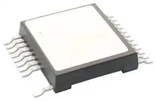


MMIX1H60N150V1
Thyristor, 1.5 kV, SMPD, 24 Pins
- Manufacturer: LITTELFUSE
- Product type: Thyristors - SCRs
- MSL: -
- SVHC: To Be Advised
- No. of Pins: 24Pins
- Product Range: -
- Thyristor Mounting: Surface Mount
- Holding Current Max: 350A
- On State RMS Current: -
- Thyristor Case Style: SMPD
- Average On State Current: -
- Gate Trigger Current Max: -
- Gate Trigger Voltage Max: -
- Operating Temperature Max: 150°C
- Peak Non Repetitive Surge Current: -
- Peak Repetitive Off State Voltage: 1.5kV
| Delivery and price | |
|---|---|
| Units per pack | 50 |
| Price | 46.68 € |
| Current stock | 25+ |
| Lead time | 30 days |
Preliminary Technical Information ## **1500V MOS Gated MMIX1H60N150V1 Thyristor A w/ Anti-Parallel Diode** **==> picture [36 x 87] intentionally omitted <==** **----- Start of picture text -----**<br> A<br>G<br>K<br>**----- End of picture text -----**<br> ## **(Electrically Isolated Tab)** |**Symbol**|**Test Conditions**|**Maximum Ratings**|| |---|---|---|---| |**VDM**|TJ = 25°C to 150°C|1500|V| |**VGK**|Continuous<br>±30|±30|V| |**VGK**|Transient<br>±40|±40|V| |**ITSM**|TC = 25°C, 1μs<br>32.0|32.0|kA| ||TC = 25°C, 10μs<br>11.8|11.8<br>kA|kA| |**PD**|TC = 25°C|446|W| |**TJ**||-55 ... +150|°C| |**TJM**||150|°C| |**Tstg**||-55 ... +150|°C| |**TL**|Maximum Lead Temperature for Soldering 300 °C||Maximum Lead Temperature for Soldering 300 °C| |**TSOLD**|1.6 mm (0.062 in.) from Case for 10s 260||°C| |**VISOL**|50/60Hz, 1 minute|2500|V~| |**FC**|Mounting Force<br>50..200/11..45|50..200/11..45|N/lb| |**Weight**|8 g|8 g|8 g| **==> picture [24 x 17] intentionally omitted <==** **----- Start of picture text -----**<br> V<br>DM<br>**----- End of picture text -----**<br> ## **= 1500V** **==> picture [120 x 73] intentionally omitted <==** **----- Start of picture text -----**<br> A<br>G<br>K<br>**----- End of picture text -----**<br> **==> picture [146 x 135] intentionally omitted <==** **----- Start of picture text -----**<br> Isolated Tab<br>A<br>K<br>G<br>G = Gate K = Cathode<br>**----- End of picture text -----**<br> A = Anode ## **Features** - Silicon Chip on Direct-Copper Bond (DCB) Substrate - Isolated Mounting Surface - Anti-Parallel Diode - 2500V~ Electrical Isolation - Very High Current Capability |**Symbol**<br>(T= 25C, Unless Otherwise Specified)**Min. Typ. Max.**|**Min. Typ. Max.**|**Min. Typ. Max.**| |---|---|---| |(TJ= 25C, Unless Otherwise Specified)**Min. Typ. Max.**|**Min. Typ. Max.**|**Min. Typ. Max.**| |**VBR**<br>IA= 250A, VGK= 0V<br>1500 V|1500 V<br>~~—~~|1500 V| |**VGK(th)**<br>IA<br>= 250μA, VAK= VGK<br>2.5 5.0|2.5 5.0<br>~~—_~~|2.5 5.0<br>V| |**VT**<br>IT<br>= 1000A, VGK= 15V<br>4.6 6.0|4.6 6.0<br>~~—~~|4.6 6.0<br>V| |**rT**IT<br>> I**L**, VGK= 15V<br>1.2 m|1.2 m<br>~~—~~<br>~~—~~|1.2 m| |**VBO**<br>VGK= 15V<br>4.8|4.8<br>~~—~~<br>~~—~~|V| |**ID**<br>VAK = 1500V, VGK= 0V<br>TJ= 125C|15<br>1.5 mA<br>~~_~~|15<br>A<br>1.5 mA| |**IL**<br>400<br>**IH**<br>350|400<br>350<br>~~_~~<br>~~=~~|A<br>A| |**IGKS**<br>VAK = 0V, VGK=30V|<br>~~—~~|200 nA| ## **Advantages** - High Power Density - Low Gate Drive Requirement ## **Applications** - Capacitive Discharge Circuits - Ignition Circuits - Solid State Surge Protection DS100595A(6/14) © 2014 IXYS CORPORATION, All Rights Reserved **MMIX1H60N150V1** |(T= 25°C Unless Otherwise Specified)<br>**Min. Typ. Max.**<br>|**Typ. Max.**<br>|**Typ. Max.**<br>| |---|---|---| |(TJ= 25°C Unless Otherwise Specified)<br>**Min. Typ. Max.**<br>|**Typ. Max.**<br>|**Typ. Max.**<br>| |**Ciks**<br>5120<br>**Coks**VAK= 25V, VGK= 0V, f = 1MHz<br>340<br>**Crks**<br>84<br>|5120<br>340<br>84<br> ~~:~~|pF<br>pF<br>pF<br>~~:~~| |**Qg(on)**<br>180<br>**Qgk**IC= 60A, VGK= 15V, VAK= 600V<br>33<br>**Qga**<br>62<br>|180<br>33<br>62<br> ~~:~~|nC<br>nC<br>nC<br>~~:~~| |**tri**<br>100<br>**td**<br>50<br>**Capacitive Discharge, TJ = 25°C**<br>IA= 2000A, VGK= 15V, RG= 1<br>VAK= 1000V, L < 20nH,Notes 2 & 3|100<br>50<br>~~-~~|ns<br>ns<br>~~-~~| |**tri**<br>100<br>**td**<br>50<br>**Capacitive Discharge, TJ = 125°C**<br>IA= 2000A, VGK= 15V, RG= 1<br>VAK= 1000V, L < 20nH,Notes 2 & 3|100<br>50<br>~~_~~|ns<br>ns<br>~~_~~| |**RthJC**<br>**RthCS**<br>0.05<br>**RthJA**<br>19|0.28 °C/W<br>0.05<br>19<br>~~=~~|0.28 °C/W<br>°C/W<br>°C/W<br>~~=~~| ## **Reverse Diode (FRED)** |(TJ = 25°C Unless Otherwise Specified)<br>**Min. Typ. Max.**|**Min. Typ. Max.**|**Min. Typ. Max.**| |---|---|---| |(TJ = 25°C Unless Otherwise Specified)<br>**Min. Typ. Max.**|**Min. Typ. Max.**|**Min. Typ. Max.**| |**VF**<br>IF= 100A, VGK= 0V, Note 1 1.8 V|1.8 V|1.8 V| |**IRM**<br>20<br>**trr** <br>IF= 50A, VGK= 0V,<br>-diF/dt = 200A/μs, VR= 300V|20<br> 700|A<br>ns| |||| |**RthJC**||0.50C/W| Notes: 1. Pulse test, t 300μs, duty cycle, d 2%. 2. It is recommended to use a gate driver capable of supplying more than 4Amps and >15V gate voltage. 3. Refer to fig. 9 & 10. **PRELIMANARY TECHNICAL INFORMATION** The product presented herein is under development. The Technical Specifications offered are derived from a subjective evaluation of the design, based upon prior knowledge and experience, and constitute a "considered reflection" of the anticipated result. IXYS reserves the right to change limits, test conditions, and dimensions without notice. ~~a~~ IXYS Reserves the Right to Change Limits, Test Conditions, and Dimensions. IXYS MOSFETs and IGBTs are covered 4,835,592 4,931,844 5,049,961 5,237,481 6,162,665 6,404,065 B1 6,683,344 6,727,585 7,005,734 B2 7,157,338B2 by one or more of the following U.S. patents: 4,860,072 5,017,508 5,063,307 5,381,025 6,259,123 B1 6,534,343 6,710,405 B2 6,759,692 7,063,975 B2 4,881,106 5,034,796 5,187,117 5,486,715 6,306,728 B1 6,583,505 6,710,463 6,771,478 B2 7,071,537 ## **MMIX1H60N150V1** **==> picture [527 x 193] intentionally omitted <==** **----- Start of picture text -----**<br> Fig. 1. Extended Output Characteristics @ TJ = 25ºC Fig. 2. Extended Output Characteristics @ TJ = 125ºC<br>1200 1200<br>VGK = 20V V GK = 20V<br> 17V 17V<br>1000 15V 1000 13V<br> 13V 11V<br> 11V 10V<br>800 10V 800 9V<br> 8V<br>600 600<br>400 400<br>200 9V 200<br>8V 7V<br>7V 6V<br>0 0<br>0 2 4 6 8 10 12 0 2 4 6 8 10 12<br>VAK - Volts VAK - Volts<br>AmperesIA - - AmperesIA<br>**----- End of picture text -----**<br> **==> picture [530 x 408] intentionally omitted <==** **----- Start of picture text -----**<br> Fig. 3. Extended Output Characteristics @ TJ = - 40ºC Fig. 4. Gate Charge<br>16<br>1200 14 VAK = 600V<br>VGK = 20V I A = 60A<br> 17V<br>1000 15V 12 I G = 10mA<br> 13V<br>800 12V 10<br>8<br>600<br>11V 6<br>400<br>10V 4<br>200 9V<br>2<br>8V<br>7V<br>0 Le 0<br>0 2 4 6 8 10 12 0 20 40 60 80 100 120 140 160 180 200<br>VAK - Volts QG - NanoCoulombs<br>Fig. 5. Capacitance Fig. 6. Forward Voltage Drop of Intrinsic Diode<br>10,000 180<br>160<br>C iks TJ = 25ºC<br>140<br>1,000 120 TJ = 125ºC<br>C oks 100<br>80<br>100 60<br>Crks 40<br>20<br>f = 1 MHz<br>10 = 104 0<br>0 5 10 15 20 25 30 35 40 0 0.4 0.8 1.2 1.6 2 2.4<br>VAK - VoltsAK - Volts - Volts VF - Volts<br> - Volts<br>GK<br> - AmperesIA V<br> - Amperes<br>IF<br>Capacitance - PicoFarads<br>**----- End of picture text -----**<br> **==> picture [33 x 7] intentionally omitted <==** **----- Start of picture text -----**<br> VAK - VoltsAK - Volts - Volts<br>**----- End of picture text -----**<br> © 2014 IXYS CORPORATION, All Rights Reserved ## **MMIX1H60N150V1** ## **Fig. 7. Maximum Transient Thermal Impedance** **==> picture [519 x 174] intentionally omitted <==** **----- Start of picture text -----**<br> 1<br>0.1<br>0.01<br>0.001<br>0.00001 0.0001 0.001 0.01 0.1 1 10<br>Pulse Width - Seconds<br> - ºC / W<br>(th)JC<br>Z<br>**----- End of picture text -----**<br> **Fig. 8. Cauer Thermal Network** R; Ro Ra |i Ri (|i Ri () Ci (F)|i Ri () Ci (F)| |---|---|---| |i Ri (<br>1 0.018327 0.024851|i Ri () Ci (F)<br>1 0.018327 0.024851|) Ci (F)<br>1 0.018327 0.024851| |2 0.052439 0.058268|2 0.052439 0.058268|2 0.052439 0.058268| |3 0.099100 0.208110|3 0.099100 0.208110|3 0.099100 0.208110| |4 0.048364 4.000000|4 0.048364 4.000000|4 0.048364 4.000000| **Fig. 9. Capacitive Discharge Circuit** **Fig. 10. Capacitive Discharge Waveform** IXYS Reserves the Right to Change Limits, Test Conditions, and Dimensions. IXYS REF: MMIX1_60N150V1(8A) 02-19-14 ## **MMIX1H60N150V1** **==> picture [5 x 6] intentionally omitted <==** **----- Start of picture text -----**<br> b<br>**----- End of picture text -----**<br> **==> picture [91 x 27] intentionally omitted <==** **----- Start of picture text -----**<br> PIN: 1 = Gate<br> 5-12 = Cathode<br> 13-24 = Anode<br>**----- End of picture text -----**<br> © 2014 IXYS CORPORATION, All Rights Reserved
Updated at June 10, 2026
Founded in 1927 and headquartered in Chicago, Illinois, Littelfuse is a premier global manufacturer of circuit protection, power control, and sensing technologies. Widely recognized for pioneering the first small, fast-acting protective fuse, the company has grown into an industry leader whose highly reliable components are essential to modern industrial, transportation, and consumer electronics applications worldwide. At the core of the Littelfuse portfolio is an expansive and industry-leading range of circuit protection solutions. This encompasses a massive selection of traditional fuses, fuse holders, and resettable PTC thermistor fuses designed to safely interrupt overcurrent conditions. To defend against electrical overstress, Littelfuse also provides advanced transient voltage suppression (TVS) technologies, including thousands of specialized TVS diodes, TVS varistors, and gas discharge tubes (GDTs) that ensure robust defense against voltage spikes and environmental hazards. Beyond its foundational protection components, Littelfuse manufactures a diverse array of discrete semiconductors, sensors, and switching devices. Engineers rely on their high-performance thyristors, including TRIACs and SCRs, alongside power-efficient Schottky diodes and MOSFETs for demanding power control applications. Complemented by precision proximity sensors and highly reliable reed and solid-state relays, Littelfuse delivers the critical building blocks required for secure, efficient, and complete system design.
About Novapart
Novapart is a B2B electronic component broker specialising in stock shortages and cost reduction. We source hard-to-find parts and identify compliant alternatives across a catalogue of 540,000+ components from 500+ manufacturers.
Learn more →Stock Shortage Specialist
When a component is unavailable, discontinued or has an unacceptable lead time, we tap into our network of vetted European and Asian distributors to source what you need — without compromising on quality or traceability.
Request a quote →Compliant Alternatives
We identify pin-to-pin, electrically equivalent substitutes that meet the same certifications (RoHS, AEC-Q100, REACH) as your original specification — validated against datasheets, not just part numbers. Often at a lower cost.
BOM Analysis service →