


MLC1265-701MLB
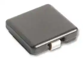
Power Inductor (SMD), 700 nH, 21 A, Shielded, 27.5 A, MLC12xx Series
- Manufacturer: COILCRAFT
- Product type: SMD Power Inductors
- Inductance:700nH; RMS Current (Irms):21A; Inductor Construction:Shielded; Saturation Current (Isat):27.5A; Product Range:-; Power Inductor Case:11.4mm x 10.5mm x 6.5mm; DC Resistan
- Inductance: 700nH
- Product Range: MLC12xx Series
- Product Width: 10.5mm
- Product Height: 6.5mm
- Product Length: 11.4mm
- DC Resistance Max: 0.7ohm
- RMS Current (Irms): 21A
- Inductance Tolerance: ± 20%
- Inductor Construction: Shielded
- Saturation Current (Isat): 27.5A
| Delivery and price | |
|---|---|
| Units per pack | 100 |
| Price | 1.25 € |
| Current stock | 10+ |
| Lead time | 30 days |
Document 327-1

## **Shielded Power Inductors MLC12xx/15xx**

- Soft saturation makes them ideal for VRD/VRM applications

- Special materials eliminate all thermal aging issues.

**Designer’s Kit C387** contains samples of all values **Core material** Iron

**Core and winding loss** See www.coilcraft.com/coreloss **Terminations** RoHS tin-silver over copper. Other terminations available at additional cost.

**Weight** MLC12xx 1.91 – 3.04 g;  MLC15xx 2.73 – 5.12 g **Ambient temperature** –40°C to +85°C with I rms current

**Maximum part temperature:** The part may be operated without damage as long its temperature (ambient + self-heating) does not exceed +125°C.

**Storage temperature** Component: –40°C to +125°C. Packaging: –40°C to +80°C

**Resistance to soldering heat** Max three 40 second reflows at +260°C, parts cooled to room temperature between cycles **Moisture Sensitivity Level (MSL)** 1 (unlimited floor life at <30°C / 85% relative humidity)

**Failures in Time (FIT) / Mean Time Between Failures (MTBF)** 38 per billion hours / 26,315,789 hours, calculated per Telcordia SR-332 **PCB washing** Only pure water or alcohol recommended

||**Inductance**2|**DCR(mOhm) **|**DCR(mOhm) **|**SRF typ**3|**Isat**|**sat(A)**4|**Irms**|**rms(A)**5|**Height**|
|---|---|---|---|---|---|---|---|---|---|
|**Part number**1|**±20%(µH)**|**typ   max**||**(MHz)**|**10% drop 20% dro**|**20% drop**|**20°C rise 40°C rise**|**20°C rise 40°C rise**|**max(mm)**|
|**10.5 mm × 11.x mm body size (see next page for 13.2 mm × 14.xmm body size)**|**10.5 mm × 11.x mm body size (see next page for 13.2 mm × 14.xmm body size)**||||**10.5 mm × 11.x mm body size (see next page for 13.2 mm × 14.xmm body size)**|||||
|MLC1265-361ML_|0.36|0.93|1.03|234|26.9|42.6|16.5|22.7|6.5|
|MLC1260-401ML_|0.40|0.93|1.03|228|21.0|35.2|16.3|21.9|6.1|
|MLC1255-421ML_|0.42|0.93|1.03|219|21.1|34.5|16.8|24.1|5.6|
|MLC1240-451ML_|0.45|1.73|1.91|198|16.5|24.9|12.8|19.8|4.1|
|MLC1265-701ML_|0.70|1.24|1.37|134|16.4|27.5|15.2|21.0|6.5|
|MLC1250-801ML_|0.80|2.35|2.59|151|13.3|21.7|12.4|17.3|5.1|
|MLC1240-901ML_|0.90|2.57|2.83|108|13.9|22.8|11.9|16.3|4.1|
|MLC1260-122ML_|1.20|2.38|2.62|93|14.0|23.3|12.3|17.6|6.1|
|MLC1255-122ML_|1.20|2.38|2.62|85|14.1|22.4|12.4|17.5|5.6|
|MLC1250-132ML_|1.30|2.38|2.62|76|10.8|17.7|11.7|16.5|5.3|
|MLC1245-152ML_|1.50|4.08|4.49|79|10.7|17.3|10.3|14.2|4.6|
|MLC1260-172ML_|1.75|2.84|3.13|72|12.1|19.2|10.9|15.3|6.1|
|MLC1245-402ML_|4.00|8.18|9.00|46|7.42|11.8|6.9|9.8|4.8|


## 1. When ordering, please specify **termination** and **packaging** codes: ~~——|~~ **MLC1245-402MLC**

**Termination: L** = RoHS compliant tin-silver over copper.

Special order: **T** = RoHS tin-silver-copper (95.5/4/0.5) or **S** = non-RoHS tin-lead (63/37). **Packaging: C** = 7″ machine-ready reel. EIA-481 embossed plastic tape.

- **B** = Less than full reel. In tape, but not machine ready. To have a leader and trailer added ($25 charge), use code letter C instead.

- **D** = 13″ machine-ready reel. EIA-481 embossed plastic tape. Factory order only, not stocked.

2. Inductance measured at 100 kHz, 0.1 Vrms, 0 Adc using a Coilcraft SMD ‑A fixture in an Agilent/HP 4284A LCR meter.

3. SRF measured using an Agilent/HP4291A impedance analyzer and a Coilcraft 16193 fixture.

4. DC current at which the inductance drops the specified amount from its value without current.

5. Current that causes the specified temperature rise from 25°C ambient.

6. Electrical specifications at 25°C.

Refer to Doc 362 “Soldering Surface Mount Components” before soldering.

**US** +1-847-639-6400   sales@coilcraft.com **UK** +44-1236-730595   sales@coilcraft-europe.com **Taiwan** +886-2-2264 3646   sales@coilcraft.com.tw **China** +86-21-6218 8074   sales@coilcraft.com.cn **Singapore** + 65-6484 8412   sales@coilcraft.com.sg

## Document 327-1 Revised 04/19/12

© Coilcraft Inc. 2012 This product may not be used in medical of high risk applications without prior Coilcraft approval. Specification subject to change without notice. Please check out web site for latest information.

Document 327-2

**==> picture [50 x 114] intentionally omitted <==**

## **Shielded Power Inductors – MLC12xx/15xx Series**

|**Inductance**2<br>  **Part number**1<br>**±20%(µH)**|**DCR (mOhm)**<br>**SRF typ**3<br>**typ   max**<br>**(MHz)**||**Isat (A)**4<br>**10% drop 20% drop**|**Isat (A)**4<br>**10% drop 20% drop**|**Isat (A)**4<br>**10% drop 20% drop**|**Isat (A)**4<br>**10% drop 20% drop**|**Isat (A)**4<br>**10% drop 20% drop**|**Isat (A)**4<br>**10% drop 20% drop**|**Isat (A)**4<br>**10% drop 20% drop**|**Isat (A)**4<br>**10% drop 20% drop**|**Irms (A)**5<br>**Height**<br>**20°C rise 40°C rise**<br>**max(mm)**|
|---|---|---|---|---|---|---|---|---|---|---|---|
|**13.2 mm × 14.x mm body size (see previous page for 10.5 mm × 11.x**<br>MLC1565-451ML_<br>0.45<br>0.864<br>0.951<br>158<br>MLC1565-501ML_<br>0.50<br>0.864<br>0.951<br>132<br>MLC1555-551ML_<br>0.55<br>1.34<br>1.48<br>165<br>MLC1565-801ML_<br>0.80<br>1.20<br>1.32<br>93||**mm body size)**<br>32.8<br>54.0<br>21.3<br>38.1<br>20.8<br>35.7<br>27.4<br>47.4|||||||||18.0<br>25.6<br>6.5<br>18.6<br>26.9<br>6.5<br>16.1<br>22.3<br>5.6<br>17.4<br>24.6<br>6.5|
|MLC1560-901ML_<br>0.90<br>1.72<br>1.90<br>101<br>MLC1538-102ML_<br>1.0<br>3.46<br>3.81<br>81<br>MLC1550-102ML_<br>1.0<br>1.72<br>1.90<br>76<br>MLC1565-142ML_<br>1.4<br>2.20<br>2.42<br>77<br>MLC1538-152ML_<br>1.5<br>4.36<br>4.80<br>50||||17.8<br>28.7<br>13.6<br>21.2<br>16.1<br>27.3<br>18.9<br>30.1<br>13.4<br>21.0|||||||14.6<br>20.6<br>6.0<br>11.5<br>16.7<br>3.9<br>13.9<br>19.7<br>5.2<br>13.7<br>19.9<br>6.5<br>10.6<br>14.6<br>3.9|
|MLC1565-202ML_<br>2.0<br>3.56<br>3.82<br>64<br>MLC1550-252ML_<br>2.5<br>3.43<br>3.74<br>45<br>MLC1565-282ML_<br>2.8<br>4.10<br>4.51<br>44<br>MLC1555-302ML_<br>3.0<br>4.06<br>4.47<br>42<br>MLC1565-372ML_<br>3.7<br>3.10<br>3.40<br>47||||15.2<br>24.2<br>10.9<br>17.7<br>13.7<br>22.3<br>11.1<br>18.1<br>8.13<br>13.63|||||||11.6<br>16.3<br>6.5<br>11.5<br>15.8<br>5.2<br>10.7<br>15.2<br>6.5<br>10.9<br>15.6<br>5.6<br>12.17<br>16.58<br>6.5|
|MLC1550-452ML_<br>4.5<br>7.13<br>7.85<br>36<br>MLC1565-472ML_<br>4.7<br>4.00<br>4.40<br>39<br>MLC1565-602ML_<br>6.0<br>5.50<br>6.05<br>34<br>MLC1565-732ML_<br>7.3<br>7.20<br>7.92<br>29<br>MLC1565-922ML_<br>9.2<br>9.70<br>10.60<br>25||||7.12<br>11.8<br>6.23<br>10.57<br>5.60<br>9.57<br>5.10<br>8.60<br>4.57<br>7.80|||||||8.43<br>11.7<br>5.2<br>10.98<br>15.57<br>6.5<br>9.27<br>13.62<br>6.5<br>8.60<br>12.01<br>6.5<br>7.19<br>10.18<br>6.5|
|MLC1565-113ML_<br>11.3<br>10.60<br>11.60<br>21<br>MLC1565-133ML_<br>13.0<br>12.57<br>13.75<br>19<br>MLC1565-153ML_<br>15.4<br>16.40<br>18.00<br>17<br>1. When ordering, please specify**termination**and**packaging**codes:<br>**MLC1565-153MLC**<br>**Termination: L**= RoHS compliant tin-silver over copper.<br>Special order:<br>**T**= RoHS tin-silver-copper (95.5/4/0.5)<br>or**S**= non-RoHS tin-lead (63/37).<br>**Packaging: C**= 7″ machine-ready reel. EIA-481 embossed plastic<br>tape.<br>**B**= Less than full reel. In tape, but not machine ready.<br>To have a leader and trailer added ($25 charge), use<br>code letter C instead.<br>**D**= 13″ machine-ready reel. EIA-481 embossed plastic<br>tape. Factory order only, not stocked.<br>2. Inductance measured at 100 kHz, 0.1 Vrms, 0 Adc using a Coilcraft<br>SMD ‑A fxture in an Agilent/HP 4284A LCR meter.<br>3. SRF measured using an Agilent/HP4291A impedance analyzer and a<br>Coilcraft 16193 fxture.<br>4. DC current at which the inductance drops the specifed amount from its<br>value without current.<br>5. Current that causes the specifed temperature rise from 25°C ambient.<br>6. Electrical specifcations at 25°C.<br>Refer to Doc 362 “Soldering Surface Mount Components” before soldering.<br>**Tape and Reel**(24 mm wide plastic tape)<br>  Quantity<br>Tape thickness<br>Pocket<br>Pocket<br>7″reel 13″reel<br>(mm)<br>spacing (mm)depth(mm)<br>**MLC1240**<br>250<br>900<br>0,35<br>16<br>4,45<br>**MLC1245**<br>200<br>800<br>0,35<br>16<br>4,95<br>**MLC1250**<br>200<br>700<br>0,40<br>16<br>5,45<br>**MLC1255**<br>200<br>700<br>0,40<br>16<br>5,95<br>**MLC1260**<br>175<br>600<br>0,40<br>16<br>6,50<br>**MLC1265**<br>150<br>600<br>0,40<br>16<br>6,70<br>**MLC1538**<br>200<br>800<br>0,35<br>20<br>4,00<br>**MLC1550**<br>150<br>600<br>0,40<br>20<br>5,45<br>**MLC1555**<br>150<br>500<br>0,40<br>20<br>5,95<br>**MLC1560**<br>150<br>500<br>0,40<br>20<br>6,20<br>**MLC1565**<br>125<br>500<br>0,40<br>20<br>6,50||||4.07<br>7.03<br>3.93<br>6.70<br>3.43<br>5.77|||||||6.87<br>9.46<br>6.5<br>6.12<br>8.65<br>6.5<br>5.63<br>7.75<br>6.5<br>D<br>E<br>E<br>F<br>G<br>**Recommended**<br>**Land Pattern**<br>Parts manufactured prior<br>to March 2012 may be<br>marked differently.<br>Part number<br>Internal code<br>**D**<br>**E**<br>**F**<br>**G**|
||||||B<br>C<br>MLCxxx<br>-xxxML<br>XXXX Y||||||D<br>G<br>**Recommen**<br>**Land Patt**<br>Parts manufactured prior<br>to March 2012 may be<br>marked differently.<br>Part number<br>Internal code|
|||||A||||||||
|||||||||||||
||||||B|||||||
|||Max height.<br>See electrical<br>specifications<br>table.||||||||||
|||||||||||||
|||||||||||||
||||||C|||||||
|||||||||||||
|||||||||||||
|||||||||||||
|||||||||||||
|||**Body**<br>**A**<br>**Size**<br>**ma**|||<br>**B**<br>**x**<br>**max**|||<br>**C**||||
|||1240<br>11.2<br>10.5<br>1.8<br>1245<br>11.2<br>10.5<br>1.8<br>1250<br>11.2<br>10.5<br>1.8<br>1255<br>11.4<br>10.5<br>1.8<br>1260<br>11.4<br>10.5<br>1.8<br>1265<br>11.4<br>10.5<br>1.8|||||||||2.3<br>4.0<br>4.0<br>2.7<br>2.3<br>4.0<br>4.0<br>2.7<br>2.3<br>4.0<br>4.0<br>2.7<br>2.3<br>4.0<br>4.0<br>2.7<br>2.3<br>4.0<br>4.0<br>2.7<br>2.3<br>4.0<br>4.0<br>2.7|
|**MLC1240**<br>**MLC1245**<br>**MLC1250**<br>**MLC1255**<br>**MLC1260**<br>**MLC1265**<br>**MLC1538**<br>**MLC1550**<br>**MLC1555**<br>**MLC1560**<br>**MLC1565**||||||||||||
|||1538<br>13.8<br>13.2<br>2.4<br>1550<br>13.8<br>13.2<br>2.4<br>1555<br>13.8<br>13.2<br>2.4<br>1560<br>13.8<br>13.2<br>2.4<br>1565<br>14.0<br>13.2<br>2.4|||||||||3.0<br>5.0<br>5.4<br>3.4<br>3.0<br>5.0<br>5.4<br>3.4<br>3.0<br>5.0<br>5.4<br>3.4<br>3.0<br>5.0<br>5.4<br>3.4<br>3.0<br>5.0<br>5.4<br>3.4|
|||All dimensions are in mm.||||||||||


Document 327-2 Revised 04/19/12

**US** +1-847-639-6400   sales@coilcraft.com **UK** +44-1236-730595   sales@coilcraft-europe.com **Taiwan** +886-2-2264 3646   sales@coilcraft.com.tw **China** +86-21-6218 8074   sales@coilcraft.com.cn **Singapore** + 65-6484 8412   sales@coilcraft.com.sg

**==> picture [116 x 44] intentionally omitted <==**

© Coilcraft Inc. 2012 This product may not be used in medical of high risk applications without prior Coilcraft approval. Specification subject to change without notice. Please check out web site for latest information.

Document 327-3

**==> picture [50 x 114] intentionally omitted <==**

## **Shielded Power Inductors – MLC12xx/15xx Series**

## **Typical L vs Current**

## **Typical L vs Frequency**

**==> picture [243 x 185] intentionally omitted <==**

**----- Start of picture text -----**<br>
100<br>MLC1565-153<br>10 MLC1565-922<br>MLC1550-452<br>MLC1565-282<br>MLC1538-152<br>MLC1538-102<br>1<br>MLC1555-551<br>MLC1265-361<br>0.1<br>0.01 0.1 1 10<br>Frequency (MHz)<br>Inductance (µH)<br>**----- End of picture text -----**<br>


**==> picture [242 x 185] intentionally omitted <==**

**----- Start of picture text -----**<br>
100<br>MLC1565-153<br>10 MLC1565-922<br>MLC1550-452<br>MLC1565-282<br>MLC1538-152<br>MLC1538-102<br>1<br>MLC1555-551<br>MLC1265-361<br>0.1<br>0.1 1 10 100<br>Current (A)<br>Inductance (µH)<br>**----- End of picture text -----**<br>


Inductance vs current is unaffected by part temperature up to 125°C.

## **Temperature Rise vs Current**

**==> picture [242 x 185] intentionally omitted <==**

**----- Start of picture text -----**<br>
70<br>60<br>50<br>40<br>30<br>20<br>10<br>0<br>0 5 10 15 20 25 30<br>Current (Arms)<br>MLC1565-153 MLC1565-922MLC1550-452 MLC1538-152MLC1565-282MLC1538-102MLC1260-122 MLC1555-551MLC1265-361<br>Temperature rise (from 25°C)<br>**----- End of picture text -----**<br>


**==> picture [116 x 44] intentionally omitted <==**

Document 327-3 Revised 04/19/12

© Coilcraft Inc. 2012 This product may not be used in medical of high risk applications without prior Coilcraft approval. Specification subject to change without notice. Please check out web site for latest information.

**US** +1-847-639-6400   sales@coilcraft.com **UK** +44-1236-730595   sales@coilcraft-europe.com **Taiwan** +886-2-2264 3646   sales@coilcraft.com.tw **China** +86-21-6218 8074   sales@coilcraft.com.cn **Singapore** + 65-6484 8412   sales@coilcraft.com.sg
Updated at March 10, 2026
Coilcraft is a globally recognized leader in the design and manufacture of high-performance magnetic components. Renowned for its engineering excellence, reliable delivery, and stringent quality standards, the company provides essential solutions for a wide array of demanding applications, including signal processing, RF, power management, and timing circuits. Our comprehensive portfolio of Coilcraft components is centered on their industry-leading inductor technologies. This encompasses a vast selection of high-efficiency power inductors designed to optimize modern power supply architectures, alongside precision RF inductors engineered to deliver exceptional stability and performance in high-frequency communications and wireless applications. To support complete electromagnetic compatibility and comprehensive circuit design, we also offer a variety of Coilcraft's specialized magnetic solutions. This includes robust common mode chokes and filters for effective EMC and RFI suppression, current sensing transformers, and a selection of inductor kits and assortments that provide design engineers with versatile options for rapid prototyping and development.
About Novapart
Novapart is a B2B electronic component broker specialising in stock shortages and cost reduction. We source hard-to-find parts and identify compliant alternatives across a catalogue of 410,000+ components from 500+ manufacturers.
Learn more →Stock Shortage Specialist
When a component is unavailable, discontinued or has an unacceptable lead time, we tap into our network of vetted European and Asian distributors to source what you need — without compromising on quality or traceability.
Request a quote →Compliant Alternatives
We identify pin-to-pin, electrically equivalent substitutes that meet the same certifications (RoHS, AEC-Q100, REACH) as your original specification — validated against datasheets, not just part numbers. Often at a lower cost.
BOM Analysis service →