
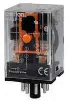


MK2KP-UA-AC120
RELAY, DPDT, 220VAC, 24VDC, 5A
- Manufacturer: OMRON INDUSTRIAL AUTOMATION
- Product type: Power Relays
- Coil Type: Non Latching
- Coil Voltage: 120VAC
- Product Range: MK Series
- Relay Mounting: Socket
- Coil Resistance: 1.9kohm
- Contact Current: 5A
- Relay Terminals: Quick Connect
- Contact Material: Silver
- Contact Voltage VAC: 220VAC
- Contact Voltage VDC: 24VDC
- Contact Configuration: DPDT
| Delivery and price | |
|---|---|
| Units per pack | 5 |
| Price | 47.12 € |
| Current stock | 25+ |
| Lead time | 7 days |
**Latching Relay MKK**

CSM_MKK_DS_E_2_1

## **Latching Relays Designed for Memory and Signaling Circuits**

- Low changes in characteristics such as contact tracking and contact pressure for high durable.

- Excellent resistance to vibration and shock.

- Built-in operation indicators for simple operation verification.

- Same external shape with the MK Power Relays.

**Refer to the** _**Common Relay Precautions**_ **.**

## **Ordering Information**

## **List of Models**

## **Encased Models and Models with Plug-in Terminals**

|**Number of poles**<br>**Classification**|**2poles**|**2poles**|
|---|---|---|
||**Model**|**p**<br>**Rated voltage (V)**|
|**Standard models**|**MK2KP**|**g**<br>6, 12, 24, 50, 100/(110), or<br>200/(220)VAC|


|**Number of poles**<br>**Classification**|**2poles**|**2poles**|
|---|---|---|
||**Model**|**Rated voltage (V)**|
|**Standard models**|**MK2KP**|6,12,24,48,100,or 110 VDC|


## **Ratings and Specifications**

**==> picture [333 x 346] intentionally omitted <==**

**----- Start of picture text -----**<br>
Ratings<br>Operating Coil<br>Power<br>Item Set coil Reset coil Set  Reset  Maximum  consumption (W, VA)<br>Rated voltage  current Rated  Resis-tance  current Rated  Resis-tance  voltage (V) voltage (V) voltage (V) Set coil Reset coil<br>(V) (mA) ( Ω ) (mA) ( Ω )<br>Pepe 6 286 4.8 29.0 78 | | ee<br>a 12 128 25 14.4 325<br>24 66 105 10.8 965 Approx.  Approx.<br>AC 110% 1.5 0.1<br>a 50 31 440 3.2 8,450 to 2 to 0.7<br>a 100/(110) 17.8 1,670 3.6 13,350<br>[fy 200/(220) 9.8 6,200 [| 3.2 27,350 80% max. 80% max.<br>6 390 13 92.5 64<br>a 12 205 52 50 240<br>24 110 210 22.8 1,050 Approx.  Approx.<br>DC Cf |; | |_| 110% 2.3 0.5<br>a 48 48.5 990 23.4 2,050 to 2.7 to 1.2<br>a 100 24 4,160 10.3 9,740<br>a 110 26.4 4,160 11.3 9,740<br>Note: 1. The rated current for AC is the value measured with a DC ammeter in 60 Hz half-wave rectification.<br>The 100/(110) and 200/(220) VAC rated voltages are the values at 100 and 200 VAC.<br>2. The rated current and coil resistance are measured at a coil temperature of 23°C with tolerances of +15%/–20%<br>for the AC rated current and ±15% for the DC coil resistance.<br>3. The AC coil resistance is a reference value only.<br>4. Operating characteristics were measured at a coil temperature of 23°C.<br>5. The maximum allowable voltage is the maximum value of the allowable voltage fluctuation range for the Relay coil<br>operating power supply and was measured at an ambient temperature of 23°C.<br>There is no continuous allowance.<br>6. The initial reverse voltage of the built-in diode is 1,000 V.<br>The initial reverse voltage of the built-in diode in some models is 2,000 V. (MK2KPD)<br>Contact Ratings<br>Item Load Resistive load Inductive load (cos  φ  = 0.4, L/R =<br>7 ms)<br>Contact structure Single<br>Contact materials Ag<br>Rated load 5 A at 220 VAC, 3 A at 24 VDC 2 A at 220 VAC, 2.5 A at 24 VDC<br>Rated carry current 5 A<br>Maximum contact voltage 250 VAC, 250 VDC<br>Maximum contact current 5 A<br>Maximum switching capacity<br>1,100 VA, 72 W 440 VA, 60W<br>(reference value)<br>**----- End of picture text -----**<br>


## **Characteristics**

**==> picture [152 x 297] intentionally omitted <==**

**----- Start of picture text -----**<br>
Contact resis-<br>tance [*] [1] 50 m Ω  max.<br>Time 30 ms max. (when rated operating power<br>Set is applied, not including contact bounce.)<br>Minimum<br>60 ms<br>pulse width<br>Re-set Time 30 ms max. (when rated operating power is applied, not including contact bounce.)<br>Minimum pulse width 60 ms<br>Maximum  Mechanical 1,800 operations/hr<br>operating frequency Rated load 1,800 operations/hr<br>Insulation resis- 100 M Ω  min. for 500 VDC applied to the<br>tance same location as for dielectric strength<br>measurement<br>Between coil and<br>contacts<br>2,000 VAC at 50/60 Hz for 1 min.<br>Between contacts<br>Dielectric  of different polarity<br>strength Between contacts<br>of the same polarity 1,000 VAC at 50/60 Hz for 1 min.<br>Between set/reset<br>coils<br>Vibra- Destruction 10 to 55 to 10 Hz, 0.75-mm single<br>tion re- amplitude (1.5-mm double amplitude)<br>sistance Malfunction 10 to 55 to 10 Hz, 0.5-mm single<br>amplitude (1.0-mm double amplitude)<br>Shock  Destruction 500 m/s [2]<br>resis-<br>tance Malfunction 100m/s [2]<br>Mechanical 5,000,000 operations min. (operating<br>Endur- frequency: 1,800 operations/hr)<br>ance Electrical [*] [2] 500,000 operations min. (rated load,<br>switching frequency: 1,800 operations/h)<br>Failure rate P value<br>10 mA at 1 VDC<br>(reference value [*] [3] )<br>Weight Approx. 85 g<br>Note: The above values are initial values.<br>*1. Measurement conditions: 1 A at 5 VDC using the<br>voltage drop method<br>**----- End of picture text -----**<br>


- *2. Ambient temperature condition: 23 ° C

- *3. This value was measured at a switching frequency of 60 operations per minute.

**Ambient operating** − 10 to 40 ° C (with no icing or **temperature** condensation) **Ambient operating** 5% to 85% **humidity**

**1**

**MKK**

## **Engineering Data**

## **Maximum Switching Capacity**

## **Endurance Curve**

## **Malfunctioning Shock**

**==> picture [67 x 8] intentionally omitted <==**

**----- Start of picture text -----**<br>
MK2KP  24 VDC<br>**----- End of picture text -----**<br>


**==> picture [503 x 682] intentionally omitted <==**

**----- Start of picture text -----**<br>
10 1.000<br>AC resistive load 500<br>5 Y Set<br>220 VAC resistive load<br>DC resistive load Reset<br>100 24 VDC resistive load<br>AC inductive load  X Z<br>1 (cos  φ  = 0.4) 50 230 150 580<br>0.5 DC inductive load  (L/R = 7 ms) 24 VDC inductive load (L/R = 7 ms) 120 320<br>10 220 VAC inductive load  (cos  φ  = 0.4) 230<br>5 320 490<br>350<br>Z' 490 X'<br>0.1<br>490 Unit: m/s [2]<br>1<br>5        10                      50    100                     500 1.000 0 1 2 3 4 5 6 7 8 9 10<br>Contact voltage (V) Contact current (A) Y'<br>Ambient Temperature and the Set and Reset Voltages  Measurement: Measurement: Shock was<br>MK2KP  100/(110) VAC MK2KP  24 VDC applied 3 times each in 6<br>directions along 3 axes with<br>100 100 the Relay set and reset to<br>Number of Relays: 5 Set voltage Number of Relays: 5 Set voltage check the shock values that<br>Reset voltage Reset voltage cause the Relay to<br>80 80 malfunction.<br>Criteria: 100m/s [2]<br>60 60<br>40 40<br>20 20<br>0 − 40  − 20  0  20  40  60  80 0 − 40  − 20  0  20  40  60  80<br>Ambient temperature ( ° C) Ambient temperature ( ° C)<br>Ambient Temperature vs. Coil Temperature Rise<br>MK2KP  100/(110) VAC MK2KP  24 VDC<br>100 100<br>Number of Relays: 5<br>80 80<br>60 60<br>40 40<br>20 20<br>0 − 40        − 20             0            20           40            60        80 − 040           − 20           0            20           40           60         80<br>Ambient temperature ( ° C) Ambient temperature ( ° C)<br>Changes in Operation Characteristics Due to External Magnetic Fields Degradation in Latching Ability Over Time<br>MK2KP  100 VAC (Average Value) MK2KP  200 VAC<br>N=5 N=20<br>Measurement: The percentage of change in the operating  Measurement: The rate of deterioration in latching ability<br>and release voltages in a uniform external magnetic field  was measured over time with the Relay left at a normal<br>were measured (worst magnetic field direction). temperature (20 to 30°C) after latching by applying the<br>rated voltage.<br>N S S N<br>+80<br>+60 100<br>+40<br>+20 max<br>70 50 50 70<br>min<br>-20 50<br>-40<br>-60<br>-80 Set voltage<br>Reset voltage<br>0 50100         300 5001,000    3,000 5,000 10,000<br>Uniform magnetic field strength (0e)<br>Elapsed time (h)<br>4 operations)<br>Contact current (A)<br>Number of operations (×10<br>Set/reset voltage (%) Set/reset voltage (%)<br>C)Coil temperature rise ( ° C)Coil temperature rise ( °<br>Percentage change (%)<br>Latching deterioration over time (%)<br>**----- End of picture text -----**<br>


## **Ambient Temperature and the Set and Reset Voltages**

**MK2KP** 100/(110) VAC

## **Ambient Temperature vs. Coil Temperature Rise**

**MK2KP** 100/(110) VAC

**Changes in Operation Characteristics Due to External Magnetic Fields**

## **MK2KP** 100 VAC (Average Value)

**2**

**MKK**

**Dimensions**

**(Unit: mm)**

## **List of Models**

## **MK2KP**

**==> picture [416 x 152] intentionally omitted <==**

**----- Start of picture text -----**<br>
Terminal Arrangement/In-<br>ternal Connections  Note: 1. R is a resistor for<br>(Bottom View) ampere-turn<br>SET correction.<br>RESET R This resistor is<br>( − ) ( − ) 10 11 1 2 ( + ) ( + ) included in models for 50 VAC or 48 VDC or<br>34.5 max.<br>9 3 higher.<br>8 4 2. For DC models,<br>7 6 5 check the coil polarity<br>34.5 max. 52.5 max. for both the set and<br>reset coils and wire all<br>connections<br>correctly. If the<br>connections are not<br>correct, unintended<br>operation may occur.<br>**----- End of picture text -----**<br>


**3.** For AC models, the set and reset coils have no coil polarity.

**Connection Sockets** (Refer to _Common Socket and DIN Track Products_ for external dimensions.)

|**Front-mounting Sockets**|**Back-mounting Sockets**|**Back-mounting Sockets**|**Back-mounting Sockets**|
|---|---|---|---|
|Track or screw mounting|Solder terminals|Wrapping terminals|Relays with PCB<br>Terminals|
|PF113A(-E)|PL11|PL11-Q|PLE11-0|


- **Note:** Details about the Relay Hold-down Clips are the same as for the standard MK Relays.

Refer to _Common Sockets and DIN Tracks_ .

## **Mounting Height with Sockets**

The mounting height is the same as the MK. Refer to the information on the MK for details.

## **Safety Precautions**

**Refer to the** _**Common Relay Precautions**_ **for precautions that apply to all Relays.**

## **Precautions for Correct Use**

## **Circuit Conditions**

- Do not apply a voltage to the set and reset coils at the same time. If you apply a voltage to both coils simultaneously, the Relay will be set.

- There is usually no reason to use a Latching Relay with a constant current flow because the Relay can be latched with a single pulse. Using only a single pulse is also beneficial to reduce power consumption.

## **Minimum Pulse Width**

- The minimum pulse width in the performance column is the value for the following measurement conditions: an ambient temperature of 23 ° C with the rated operating voltage applied to the coil. The performance values given here may not be satisfied due to use over time and a reduction in latching performance due to changes in the ambient temperature or in the conditions of the application circuit.

For actual use, apply the rated operating voltage with a pulse width based on the actual load and reset the Relay at least once per year to prevent degradation over time.

- If the Relay is used in an environment with strong magnetic fields, the surrounding magnetic field can demagnetize the magnetic body and cause unintended operation. Therefore, do not use these Relays in environments with strong magnetic fields.

**3**

## Terms and Conditions Agreement

## Read and understand this catalog.

Please read and understand this catalog before purchasing the products.  Please consult your OMRON representative if you have any questions or comments.

## Warranties.

(a) Exclusive Warranty. Omron’s exclusive warranty is that the Products will be free from defects in materials and workmanship for a period of twelve months from the date of sale by Omron (or such other period expressed in writing by Omron). Omron disclaims all other warranties, express or implied.

(b) Limitations. OMRON MAKES NO WARRANTY OR REPRESENTATION, EXPRESS OR IMPLIED, ABOUT NON-INFRINGEMENT, MERCHANTABILITY OR FITNESS FOR A PARTICULAR PURPOSE OF THE PRODUCTS. BUYER ACKNOWLEDGES THAT IT ALONE HAS DETERMINED THAT THE

PRODUCTS WILL SUITABLY MEET THE REQUIREMENTS OF THEIR INTENDED USE.

Omron further disclaims all warranties and responsibility of any type for claims or expenses based on infringement by the Products or otherwise of any intellectual property right. (c) Buyer Remedy. Omron’s sole obligation hereunder shall be, at Omron’s election, to (i) replace (in the form originally shipped with Buyer responsible for labor charges for removal or replacement thereof) the non-complying Product, (ii) repair the non-complying Product, or (iii) repay or credit Buyer an amount equal to the purchase price of the non-complying Product; provided that in no event shall Omron be responsible for warranty, repair, indemnity or any other claims or expenses regarding the Products unless Omron’s analysis confirms that the Products were properly handled, stored, installed and maintained and not subject to contamination, abuse, misuse or inappropriate modification. Return of any Products by Buyer must be approved in writing by Omron before shipment. Omron Companies shall not be liable for the suitability or unsuitability or the results from the use of Products in combination with any electrical or electronic components, circuits, system assemblies or any other materials or substances or environments. Any advice, recommendations or information given orally or in writing, are not to be construed as an amendment or addition to the above warranty.

See http://www.omron.com/global/ or contact your Omron representative for published information.

## Limitation on Liability; Etc.

OMRON COMPANIES SHALL NOT BE LIABLE FOR SPECIAL, INDIRECT, INCIDENTAL, OR CONSEQUENTIAL DAMAGES, LOSS OF PROFITS OR PRODUCTION OR COMMERCIAL LOSS IN ANY WAY CONNECTED WITH THE PRODUCTS, WHETHER SUCH CLAIM IS BASED IN CONTRACT, WARRANTY, NEGLIGENCE OR STRICT LIABILITY. Further, in no event shall liability of Omron Companies exceed the individual price of the Product on which liability is asserted.

## Suitability of Use.

Omron Companies shall not be responsible for conformity with any standards, codes or regulations which apply to the combination of the Product in the Buyer’s application or use of the Product. At Buyer’s request, Omron will provide applicable third party certification documents identifying ratings and limitations of use which apply to the Product. This information by itself is not sufficient for a complete determination of the suitability of the Product in combination with the end product, machine, system, or other application or use. Buyer shall be solely responsible for determining appropriateness of the particular Product with respect to Buyer’s application, product or system. Buyer shall take application responsibility in all cases.

NEVER USE THE PRODUCT FOR AN APPLICATION INVOLVING SERIOUS RISK TO LIFE OR PROPERTY OR IN LARGE QUANTITIES WITHOUT ENSURING THAT THE SYSTEM AS A WHOLE HAS BEEN DESIGNED TO ADDRESS THE RISKS, AND THAT THE OMRON PRODUCT(S) IS PROPERLY RATED AND INSTALLED FOR THE INTENDED USE WITHIN THE OVERALL EQUIPMENT OR SYSTEM.

## Programmable Products.

Omron Companies shall not be responsible for the user’s programming of a programmable Product, or any consequence thereof.

## Performance Data.

Data presented in Omron Company websites, catalogs and other materials is provided as a guide for the user in determining suitability and does not constitute a warranty. It may represent the result of Omron’s test conditions, and the user must correlate it to actual application requirements. Actual performance is subject to the Omron’s Warranty and Limitations of Liability.

## Change in Specifications.

Product specifications and accessories may be changed at any time based on improvements and other reasons. It is our practice to change part numbers when published ratings or features are changed, or when significant construction changes are made. However, some specifications of the Product may be changed without any notice. When in doubt, special part numbers may be assigned to fix or establish key specifications for your application. Please consult with your Omron’s representative at any time to confirm actual specifications of purchased Product.

## Errors and Omissions.

Information presented by Omron Companies has been checked and is believed to be accurate; however, no responsibility is assumed for clerical, typographical or proofreading errors or omissions.

**In the interest of product improvement, specifications are subject to change without notice.**

## **OMRON Corporation**

## **Industrial Automation Company**

2013.6

**http://www.ia.omron.com/**

(c)Copyright OMRON Corporation 2013 All Right Reserved.
Updated at February 9, 2023
With a legacy spanning over 80 years, Omron Industrial Automation is a globally recognized leader in the manufacture of advanced industrial control and automation components. Renowned for their reliability and engineering excellence, Omron delivers comprehensive solutions that enhance efficiency, machine safety, and precision across a wide range of manufacturing environments. Our extensive portfolio of Omron products is heavily focused on their industry-leading sensing and switching technologies. We offer a vast selection of sensors, excelling specifically in high-performance proximity sensors, light sensors, and temperature sensors. Complementing this range are robust switching solutions, featuring a deep inventory of power relays, solid-state relays, safety relays, and essential relay accessories designed for demanding operational requirements. Beyond sensing and switching, Omron is highly regarded for its precision automation and process control equipment. Our selection features highly accurate temperature controllers, versatile process controllers, and sophisticated panel displays and instrumentation. To support these fundamental systems, we also supply dependable Omron power supplies, notably AC/DC converters, alongside vital connectivity components like DIN rail terminal blocks to ensure secure, efficient, and complete industrial setups.
About Novapart
Novapart is a B2B electronic component broker specialising in stock shortages and cost reduction. We source hard-to-find parts and identify compliant alternatives across a catalogue of 540,000+ components from 500+ manufacturers.
Learn more →Stock Shortage Specialist
When a component is unavailable, discontinued or has an unacceptable lead time, we tap into our network of vetted European and Asian distributors to source what you need — without compromising on quality or traceability.
Request a quote →Compliant Alternatives
We identify pin-to-pin, electrically equivalent substitutes that meet the same certifications (RoHS, AEC-Q100, REACH) as your original specification — validated against datasheets, not just part numbers. Often at a lower cost.
BOM Analysis service →