
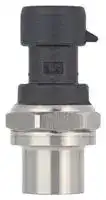


MIPAF1XX020BSAAX
Pressure Sensor, 20 bar, Voltage, Sealed Gauge, 5 VDC, 7/16
- Manufacturer: HONEYWELL
- Product type: Pressure Transducers
- Port Style: 7/16" - 20 UNF
- Product Range: MIP Series
- Sensor Output: Voltage
- Supply Current: 6.5mA
- Voltage Rating: 5VDC
- Operating Pressure Max: 20bar
- Pressure Measurement Type: Sealed Gauge
| Delivery and price | |
|---|---|
| Units per pack | 10 |
| Price | 41.35 € |
| Current stock | 50+ |
| Lead time | 7 days |
_32353264 Issue B_

## MIP SERIES

**Heavy Duty, Media-Isolated Pressure Transducers 1 bar to 12 bar | 15 psi to 175 psi**

## DESCRIPTION

The MIP Series offers a heavy duty, media-isolated pressure transducer in a compact, stainless steel construction for use with a wide range of media including aggressive fluids and water. The MIP Series provides a cost-competitive solution for wide-ranging potential applications in tough environments.

## VALUE TO CUSTOMERS

- Total Error Band (TEB) ±0.75 %FSS to ±1.0 %FSS (Full Scale Span) from -40°C to 125°C: Provides true measurement performance over the compensated temperature range; small error promotes system uptime and efficiency (see Figure 4).

- EMC performance: Operates reliably in the presence of electromagnetic fields, such as wireless signals, RF communication, and electrical devices.

- Hermetically welded design supports almost any media without the use of an internal seal. The sensors are designed to be used in harsh environments that see aggressive media.

## DIFFERENTIATION

- Diagnostics: Beneficial in applications where the sensor functionality and the need to know internal or external failure modes is critical.

- Great customer value: Multiple configuration possibilities provide flexibility of use in the application with no up front NRE or tooling charges.

- Durable: Provides the tough environmental capabilities needed, including long-term stability, insulation resistance and dielectric strength, external freeze-thaw resistance and EMC performance.

**==> picture [65 x 17] intentionally omitted <==**

**----- Start of picture text -----**<br>
NSF/ANSI/CAN 61<br>**----- End of picture text -----**<br>


## FEATURES

- Rugged, stainless steel construction

- Ratiometric output: 0.5 Vdc to 4.5 Vdc

- Operating temperature: -40°C to 125°C

- Total Error Band ±0.75 %FSS to ±1.0 %FSS (-40°C to 125°C)

- Industry-leading accuracy: ±0.15 %FSS BFSL

- Long term stability: ±0.25 %FSS

- Radiated immunity: 100 V/m

- Drinking water approval: NSF/ANSI/CAN 61

## TABLE 1. POTENTIAL APPLICATIONS

|INDUSTRY|MEDIA|
|---|---|
|Industrial:<br>pumps<br>compressors<br>process|water, hydraulic fluids<br>compressed air<br>food, beverage, oil, gas, steam|
|HVAC/R|refrigerants (butane, propane, ammonia, CO2, R134A, R407C,<br>R410A, R448A/Solstice®N40, R32 and R1234ze, R1234yf,<br>glycol + water|
|Transportation|gasoline, diesel fuel, engine oil, brake fluid, coolants, CNG|
|Medical|O2, N2, CO2, N2O, air|


- CE, RoHS, REACH compliant

- Mis-wiring protection

- Over voltage protection ±40 Vdc

## PORTFOLIO

Honeywell offers a variety of heavy duty pressure transducers for potential use in industrial and transportation applications. To view the entire product portfolio, click here.

HEAVY DUTY, MEDIA-ISOLATED PRESSURE TRANSDUCERS, MIP SERIES

TABLE 2. ELECTRICAL SPECIFICATIONS (AT 25°C [77°F] AND UNDER UNLESS OTHERWISE NOTED.)

**==> picture [542 x 95] intentionally omitted <==**

**----- Start of picture text -----**<br>
CHARACTERISTIC PARAMETER<br>Supply voltage 5.0 ±0.25 Vdc<br>Nominal output transfer function (5 Vdc supply) 0.5 Vdc to 4.5 Vdc<br>Over/reverse voltage ±40 Vdc<br>Current consumption 6.5 ±1 mA<br>Short circuit protection yes<br>**----- End of picture text -----**<br>


TABLE 3. PERFORMANCE SPECIFICATIONS (AT 25°C [77°F] AND UNDER UNLESS OTHERWISE NOTED.)

**==> picture [542 x 304] intentionally omitted <==**

**----- Start of picture text -----**<br>
CHARACTERISTIC PARAMETER<br>Operating temperature range -40°C to 125°C [-40°F to 257°F]<br>Total Error Band [1] ±1.0 %FSS (<10 bar) [2]<br>(-40°C to 125°C [-40°F to 257°F]) ±0.75 %FSS (>10 bar)<br>Accuracy BFSL [3] ±0.15 %FSS typ.<br>Long term stability (1000 hr, 25°C [77°F]) ±0.25 %FSS typ.<br>Typical output resolution 0.03 %FSS<br>Response time 1 ms (10% to 90% step change in pressure)<br>Startup time [4] <7 ms typ.<br>EMC rating (CE Conformity):<br>   surge immunity (all leads) ±1 kV line to ground per IEC 61000-4-5<br>   electrostatic discharge ±4 kV contact, ±8 kV air per IEC 61000-4-2<br>   radiated immunity  10 V/m (80 MHz to 1000 MHz) per IEC 61000-4-3<br>   fast transient burst ±1 kV per IEC 61000-4-4<br>   immunity to conducted disturbances 3 V (150 kHz to 80 MHz) per IEC 61000-4-6<br>   radiated emissions  40 dB μ V (30 MHz to 230 MHz), 47 dB μ V (230 MHz to 1000 MHz) per CISPR 11<br>Radiated immunity 100 V/m (200 MHz to 2 GHz) per ISO 11452-2<br>Insulation resistance >100 M Ω  at 1 kVdc (60 s)<br>Dielectric strength <1 mA at 500 Vac (60 s)<br>Load resistance ≥2 k Ω  (pull up or pull down)<br>Life >10 million full scale pressure cycles<br>**----- End of picture text -----**<br>


> **1Total Error Band:** The maximum deviation from the ideal transfer function over the entire compensated temperature and pressure range. Includes all errors due to offset, full scale span, pressure non-linearity, pressure hysteresis, pressure non-repeatability, thermal effect on offset, thermal effect on span, and thermal hysteresis (see Figure 4).

> **2TEB:** ±1.5 % FSS above 100°C [212°F] for pressure ratings less than 4 bar [58 psi].

> **3Accuracy:** The maximum deviation in output from a Best Fit Straight Line (BFSL) fitted to the output measured over the pressure range at 25°C [77°F]. Includes all errors due to pressure non-linearity, pressure hysteresis, and pressure non-repeatability.

> **4Startup time:** The time needed to receive valid output after power up.

TABLE 4. ENVIRONMENTAL AND MECHANICAL SPECIFICATIONS

**==> picture [542 x 148] intentionally omitted <==**

**----- Start of picture text -----**<br>
CHARACTERISTIC PARAMETER<br>Shock 100 G per MIL-STD-202, Method 213, Cond. C (at 25°C [77°F])<br>Vibration 20 G sweep, 10 Hz to 2000 Hz (at 25°C [77°F])<br>Ingress protection IP67<br>External freeze/thaw resistance >6 cycles from -30°C to 50°C [-22°F to 122°F]<br>Wetted materials:<br>   port stainless steel 304L<br>   diaphragm stainless steel 316L<br>   external seal for ports nitrile (-30°C to 100°C [-22°F to 212°F]) (other materials available)<br>Electrical connector material  PBT 30%GF (UL V-0)<br>**----- End of picture text -----**<br>


2 sensing.honeywell.com

## HEAVY DUTY, MEDIA-ISOLATED PRESSURE TRANSDUCERS, MIP SERIES

## FIGURE 1. NOMENCLATURE AND ORDER GUIDE

For example, MIPAN1XX010BSAAX defines an MIP Series Heavy Duty, Media Isolated Pressure Transducer, Metri-Pack 150, standard (UL V-0) electrical connector type, 1/4-18 NPT pressure port type, 10 bar pressure range, sealed gage pressure reference, ratiometric: 5 Vs, 10% to 90% Vs output transfer function

MIP  A  N1  X  X  010B  S  AA  X[1]

|Electrical Connector Type<br>Special<br>Output Transfer Function<br> Media Isolated Pressure<br>MIP<br>A<br>1Contact Honeywell Sales for custom configurations.<br>2Sealed gage option only available in pressure ranges at or above 8 bar | 100 psi.<br>Pressure Range<br>_bar_<br>015P<br>030P<br>050P<br>060P<br>100P<br>150P<br>175P<br>001B<br>002B<br>004B<br>006B<br>008B<br>010B<br>012B<br>1 bar<br>2 bar<br>4 bar<br>6 bar<br>8 bar<br>10 bar<br>12 bar<br>15 psi<br>30 psi<br>50 psi<br>60 psi<br>100 psi<br>150 psi<br>175 psi<br>X<br>Series<br>AA<br>_psi_<br>F1<br>7/16-20 UNF<br>1/4 inch 45° Flare<br>Female Schrader<br>(SAE J512)<br>N1<br>N2<br>1/4-18 NPT<br>(ANSI/ASME B1.20.1)<br>1/8-27 NPT<br>(ANSI/ASME B1.20.1)<br>M12 x 1.5<br>(ISO 6149-3)<br>G1/4 A-G<br>(ISO 1179-3)<br>M1<br>G1<br>Pressure Port Type<br>G1/4 A-L<br>(ISO 1179-2)<br>G2<br>Metri-Pack 150,<br>Standard (UL V-0)<br>A  Absolute<br>S  Sealed gage2<br>Special<br>X<br>X<br>Special<br>Pressure Reference<br>Ratiometric: 5.0 Vs, 10% to 90% Vs<br>~~oo~~<br>a~~n~~<br>P~~n~~<br>=<br>=e<br>~~i~~|Special<br>Output Transfer Function<br>Pressure Range<br>_bar_<br>015P<br>030P<br>050P<br>060P<br>100P<br>150P<br>175P<br>001B<br>002B<br>004B<br>006B<br>008B<br>010B<br>012B<br>1 bar<br>2 bar<br>4 bar<br>6 bar<br>8 bar<br>10 bar<br>12 bar<br>15 psi<br>30 psi<br>50 psi<br>60 psi<br>100 psi<br>150 psi<br>175 psi<br>X<br>AA<br>_psi_<br>A  Absolute<br>S  Sealed gage2<br>Special<br>X<br>Pressure Reference<br>Ratiometric: 5.0 Vs, 10% to 90% Vs<br>a~~n~~<br>P~~n~~|Special<br>Output Transfer Function<br>X<br>AA<br>A  Absolute<br>Pressure Reference<br>Ratiometric: 5.0 Vs, 10% to 90% Vs<br>a~~n~~<br>P~~n~~|Special<br>Output Transfer Function<br>X<br>AA<br>A  Absolute<br>Pressure Reference<br>Ratiometric: 5.0 Vs, 10% to 90% Vs<br>a~~n~~<br>P~~n~~|
|---|---|---|---|
||||S  Sealed gage2<br>~~n~~|
|G1/4 A-G<br>(ISO 1179-3)<br>G1||||
|G1/4 A-L<br>(ISO 1179-2)<br>G2||||
|M12 x 1.5<br>(ISO 6149-3)<br>M1||||
|N1<br>1/4-18 NPT<br>(ANSI/ASME B1.20.1)<br>=e||||
|N2<br>1/8-27 NPT<br>(ANSI/ASME B1.20.1)<br>~~i~~||||


## CAUTION PRODUCT DAMAGE DUE TO MISUSE

- Ensure torque specifications are determined for the specific application. Values provided are for reference only. (Mating materials and thread sealants can result in significantly different torque values from one application to the next.)

- Use appropriate tools (such as an open ended wrench or deep well socket) to install transducers.

- Ensure that the proper mating electrical connector with a seal is used to connect the transducer. Improper or damaged seals can compromise ingress protection, leading to short circuits.

- Ensure that filters are used upstream of the transducers to keep media flow free of large particulates and condensed moisture. MIP Series transducers are dead-end devices. Particulate accumulation may clog the port or damage the diaphragm.

- Ensure that the transducer is mounted in a vertical position with the process connection (pressure port) downward to avoid particulate deposits.

- Ensure that the media does not create a residue when dried. Build-up of residue inside the transducer may affect transducer output.

- Ensure that the transducer housing is properly grounded.

- Failure to comply with these instructions may result in product damage.

Sensing and Internet of Things 3

HEAVY DUTY, MEDIA-ISOLATED PRESSURE TRANSDUCERS, MIP SERIES

TABLE 5. PRESSURE RATINGS

**==> picture [542 x 72] intentionally omitted <==**

**----- Start of picture text -----**<br>
BAR PSI<br>OPERATING  OVER-  BURST  OPERATING  OVER-  BURST<br>PRESSURE PRESSURE [1] PRESSURE [2] PRESSURE PRESSURE [1] PRESSURE [2]<br>1 to 3 6 15 to 43.5 87<br>69 1000<br>>3 to 12 24 >43.5 to 174 348<br>**----- End of picture text -----**<br>


> **1Overpressure:** The maximum pressure which may safely be applied to the product for it to remain in specification once pressure is returned to the operating pressure range. Exposure to higher pressures may cause permanent damage to the product.

> **2Burst Pressure:** The maximum pressure which may be applied without causing escape of pressure media. The product should not be expected to function after exposure to the burst pressure.

FIGURE 2. RATIOMETRIC OUTPUT TRANSFER FUNCTION

The transfer function shown here is applicable to a ratiometric output ranging between 10% Vsupply at null pressure to 90% Vsupply at full scale pressure.

**==> picture [260 x 141] intentionally omitted <==**

**----- Start of picture text -----**<br>
Compensated Pressure Range<br>97.5 4.875<br>90 4.5<br>Ideal<br>Total<br>Error<br>Band<br>10 0.5<br>2.5 0.125<br>Pmin. Pressure Pmax.<br>Output (V) =  0.8 x VPmax. [- ] Psumin.pply x (Pressureapplied - Pmin.) + 0.10 x Vsupply<br>)<br>supply Output (Vdc)<br>Output (% V<br>**----- End of picture text -----**<br>


## FIGURE 4. TEB COMPONENTS FOR THE MIP SERIES

Total Error Band (TEB) is a single specification that includes the major sources of sensor error. TEB should not be confused with accuracy, which is actually a component of TEB. TEB is the maximum error that the sensor could experience.

Honeywell uses the TEB specification in its datasheet because it is the most comprehensive measurement of a sensor’s true accuracy. Honeywell also provides the accuracy specification in order to provide a common comparison with competitors’ literature that does not use the TEB specification.

Many competitors do not use TEB—they simply specify the accuracy of their device. Their accuracy specification, however, may exclude certain parameters. On their datasheet, the errors are listed individually. When combined, the total error (or what would be TEB) could be significant.

## FIGURE 3. ABSOLUTE VS SEALED GAGE

Example shown is for 100 psi.

**==> picture [253 x 194] intentionally omitted <==**

**----- Start of picture text -----**<br>
5<br>4.5<br>4<br>3.5<br>3<br>2.5<br>100 psi absolute<br>2<br>100 psi sealed gage<br>1.5<br>1<br>0.5<br>0<br>0 20 40 60 80 100 120 140<br>14.7 114.7<br>Pressure (psi Absolute)<br>Output (V)<br>**----- End of picture text -----**<br>


## Sources of Error

**==> picture [248 x 102] intentionally omitted <==**

**----- Start of picture text -----**<br>
Offset<br>Full Scale Span<br>Pressure Non-Linearity<br>Accuracy Total<br>Pressure Hysteresis BFSL Error<br>Pressure Non-Repeatability Band<br>Thermal Effect on Offset<br>Thermal Effect on Span<br>Thermal Hysteresis<br>**----- End of picture text -----**<br>


TABLE 6. OUTPUT DIAGNOSTIC CODES

**==> picture [542 x 95] intentionally omitted <==**

**----- Start of picture text -----**<br>
FAULT CONDITION ANALOG DIAGNOSTIC RAI L<br>Sensor internal failures 97.5% of Vsupply (See Figure 2.)<br>Over pressure 97.5% of Vsupply (See Figure 2.)<br>Under pressure (for sealed gage only) 2.5% of Vsupply (See Figure 2.)<br>Power or ground loss high (external pull-up resistor)<br>Power or ground loss low (external pull-down resistor)<br>**----- End of picture text -----**<br>


4 sensing.honeywell.com

HEAVY DUTY, MEDIA-ISOLATED PRESSURE TRA ~~NSDUCE~~ RS, MIP SERIES

## FIGURE 5. MOUNTING DIMENSIONS (FOR REFERENCE ONLY. MM/[IN]) E

## Pinout

**==> picture [261 x 87] intentionally omitted <==**

**----- Start of picture text -----**<br>
 Pin A<br>Ratiometric Voltage Output<br>Pin A = Ground<br>Pin B = V+<br>        22,0 A/F Pin C = Vout<br>[0.87]<br>  Pin C<br>Pin B<br>**----- End of picture text -----**<br>


F1: 7/16-20 UNF 1/4 inch 45° Flare Female Schrader (SAE J512) **Seal:** 45° cone **Mating geometry:** SAE J512 **Installation torque:** 17 N m [12 ft-lb] **Weight:** 36 ~~g [1.3 oz]~~

**==> picture [112 x 131] intentionally omitted <==**

**----- Start of picture text -----**<br>
Ø17,0<br>   [0.67]<br>  35,0<br>   [1.38]<br>  46,2<br>  [1.82]<br>  10,2<br>   [0.40]<br>**----- End of picture text -----**<br>


**==> picture [262 x 75] intentionally omitted <==**

**----- Start of picture text -----**<br>
Product Marking<br>MIPXXXXXXXXXXXXX<br>  16-Digit product listing<br>(Product  H    YYMMDD  XXXXX<br>marking)  Honeywell logo   5-Digit serial number  6-Digit date<br>CE NSF-61<br>  CE Mark  NSF Mark<br>**----- End of picture text -----**<br>


## G1: G1/4 A-G (ISO 1179-3)

**Seal:** O-ring (included) and retaining ring ISO 1179-3-G1/4 (not included)

**==> picture [155 x 152] intentionally omitted <==**

**----- Start of picture text -----**<br>
Mating geometry:  ISO 1179-1<br>Installation torque:  20 N m [14.7 ft-lb]<br>Weight:  33 g [1.1 oz] Ø17,0<br> [0.67]<br>  35,0<br>   [1.38]<br>  46,2<br>   [1.82]<br>  10,2<br>   [0.40]<br>**----- End of picture text -----**<br>


## G2: G1/4 A-L (ISO 1179-2)

**Seal:** ISO 9974-2/DIN 3869 profile ring (included) **Mating geometry:** ISO 1179-1 **Installation torque:** 20 N m [15 ft-lb] **Weight:** 36 g [1.3 oz]

**==> picture [110 x 137] intentionally omitted <==**

**----- Start of picture text -----**<br>
Ø17,0<br>   [0.67]<br>  35,0<br>   [1.38]<br>  49,0<br>   [1.93]<br>  10,2<br>   [0.40]<br>**----- End of picture text -----**<br>


## N1: 1/4-18 NPT

**Seal:** Pipe thread **Mating geometry:** ANSI B1.20.1 **Installation torque:** Two ~~t~~ o three ~~tu~~ rns from finger tight **Weight:** 38 g [1.3 oz]

**==> picture [108 x 139] intentionally omitted <==**

**----- Start of picture text -----**<br>
Ø17,0<br>   [0.67]<br>  35,0<br>   [1.38]<br>  50,0<br>   [1.97]<br>  10,2<br>   [0.40]<br>**----- End of picture text -----**<br>


## M1: M12 x 1.5 (ISO 6149-3)

**Seal:** O-ring (included) **Mating geometry:** ISO 614 ~~9~~ -1 **Installation torque:** 20 N m [15 ft-lb] **Weight:** 34 g [1.2 oz]

**==> picture [106 x 136] intentionally omitted <==**

**----- Start of picture text -----**<br>
Ø17,0<br>   [0.67]<br>  35,0<br>   [1.38]<br>  48,5<br>   [1.91]<br>  10,2<br>   [0.40]<br>**----- End of picture text -----**<br>


N2: 1/8-27 NPT

**Seal:** Pipe thread **Mating geometry:** ANSI B1.20.1 **Installation torque:** Two to three turns from finger tight **Weight:** 30 g [1.0 oz]

**==> picture [113 x 129] intentionally omitted <==**

**----- Start of picture text -----**<br>
Ø17,0<br>   [0.67]<br>  35,0<br>   [1.38]<br>  46,2<br>   [1.82]<br>  10,2<br>   [0.40]<br>**----- End of picture text -----**<br>


5

Sensing and Internet of Things

## ADDITIONAL MATERIALS

The following associated literature is available at sensing.honeywell.com:

- Product range guide

- Application-specific and technical information

- CAD Models

## FOR MORE INFORMATION

Honeywell Sensing and Internet of Things services its customers through a worldwide network of sales offices and distributors. For application assistance, current specifications, pricing or the nearest Authorized Distributor, visit sensing.honeywell.com or call:

## WARRANTY/REMEDY

Honeywell warrants goods of its manufacture as being free of defective materials and faulty workmanship during the applicable warranty period. Honeywell’s standard product warranty applies unless agreed to otherwise by Honeywell in writing; please refer to your order acknowledgment or consult your local sales office for specific warranty details. If warranted goods are returned to Honeywell during the period of coverage, Honeywell will repair or replace, at its option, without charge those items that Honeywell, in its sole discretion, finds defective. The foregoing is buyer’s sole remedy and is in lieu of all other warranties, expressed or implied, including those of merchantability and fitness for a particular purpose. In no event shall Honeywell be liable for consequential, special, or indirect damages.

While Honeywell may provide application assistance personally, through our literature and the Honeywell web site, it is buyer’s sole responsibility to determine the suitability of the product in the application.

Specifications may change without notice. The information we supply is believed to be accurate and reliable as of this writing. However, Honeywell assumes no responsibility for its use.

## m WARNING PERSONAL INJURY

DO NOT USE these products as safety or emergency stop devices or in any other application where failure of the product could result in personal injury.

Failure to comply with these instructions could result in death or serious injury.

USA/Canada +1 302 613 4491 Latin America +1 305 805 8188 Europe +44 1344 238258 Japan +81 (0) 3-6730-7152 Singapore +65 6355 2828 Greater China +86 4006396841

## Honeywell

Sensing and Internet of Things

830 East Arapaho Road Richardson, TX 75081 sps.honeywell.com

32353264-A-EN  |  A  |  01/21 © 2021 Honeywell International Inc. All rights reserved.
Updated at February 9, 2023
Honeywell is a globally recognized leader in the design and manufacture of advanced sensing and switching solutions. Renowned for engineering components that deliver enhanced precision and ruggedness, Honeywell provides essential technologies for demanding applications across critical healthcare, aerospace, and industrial equipment. With a comprehensive portfolio built to address both basic and complex design challenges, the company stands at the forefront of reliable electronic component manufacturing. The core of our Honeywell offering is an extensive selection of high-performance sensors and transducers. This includes a robust lineup of pressure sensors and transducers engineered for accurate fluid and gas measurement in challenging environments. Furthermore, we provide a wide array of temperature sensors and specialized temperature sensing NTC thermistors designed for stable thermal management, alongside precision current sensors and load cells that deliver critical feedback for control systems. Beyond advanced sensing technology, Honeywell’s expertise extends to essential circuit protection and electromechanical components. Our selection encompasses power relays, thermal magnetic circuit breakers, and standard terminal blocks, ensuring safe and efficient power distribution. Whether integrating core components or sourcing specialized accessories, design engineers can rely on Honeywell for uncompromising quality and operational excellence.
About Novapart
Novapart is a B2B electronic component broker specialising in stock shortages and cost reduction. We source hard-to-find parts and identify compliant alternatives across a catalogue of 410,000+ components from 500+ manufacturers.
Learn more →Stock Shortage Specialist
When a component is unavailable, discontinued or has an unacceptable lead time, we tap into our network of vetted European and Asian distributors to source what you need — without compromising on quality or traceability.
Request a quote →Compliant Alternatives
We identify pin-to-pin, electrically equivalent substitutes that meet the same certifications (RoHS, AEC-Q100, REACH) as your original specification — validated against datasheets, not just part numbers. Often at a lower cost.
BOM Analysis service →