


MIAD9LVAGQ
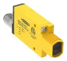
Photoelectric Sensor, 2m, 650nm Red LED, Polarised Retroreflective, Digital, 5 to 15VDC
- Manufacturer: BANNER ENGINEERING
- Product type:
- SVHC: No SVHC (25-Jun-2025)
- IP Rating: IP67
- Output Type: Digital
- Sensor Type: Photoelectric Sensor
- Light Source: 650nm Red LED
- Product Range: MINI-BEAM MIAD9 NAMUR Series
- Qualification: -
- Connection Method: 4 Pin M12 Connector
- Supply Voltage Max: 15VDC
- Supply Voltage Min: 5VDC
- Sensing Distance Max: 2m
- Operating Temperature Max: 70°C
- Operating Temperature Min: -40°C
| Delivery and price | |
|---|---|
| Units per pack | 50 |
| Price | 172.0 € |
| Current stock | 10+ |
| Lead time | 30 days |
## MINI-BEAM[®] MIAD9 NAMUR Series Sensor

## Datasheet

No revision without agency approval.

To view or download the latest technical information about this product, including specifications, dimensions, accessories, and wiring, go to www.bannerengineering.com.

- Designed for use with approved amplifiers and intrinsically safe barriers in explosive environments

-

-

-

- NAMUR compliant sensors with MINI-BEAM performance and small size

- Output 1 mA or less in the dark condition and 2 mA or more in the light condition

- Models with integral cable or quick-disconnect

## **WARNING:**

- **Do not use this device for personnel protection**

- Using this device for personnel protection could result in serious injury or death.

- This device does not include the self-checking redundant circuitry necessary to allow its use in personnel safety applications. A device failure or malfunction can cause either an energized (on) or deenergized (off) output condition.

## Models

|**Model**<br>1|**Sensing Mode**|**Sensing Beam**|**Sensing Range**|**Output Type**|
|---|---|---|---|---|
|**MI9E**|Opposed (Emitter)|Infrared, 880 nm|6 m (20 ft)|Constant Current<br>≤ 1.2 mA dark<br>≥ 2.1 mA light|
|**MIAD9R**|Opposed (Receiver)||||
|**MIAD9LVAG**|Polarized Retroreflective|Visible red, 650 nm|50 mm to 2 m (2 in to 7 ft)||
|**MIAD9LV**|Retroreflective|Visible red, 650 nm|5 m (16.4 ft)||
|**MIAD9D**|Diffuse|Infrared, 880 nm|380 mm (15 in)||
|**MIAD9W**|Divergent Diffuse|Infrared, 880 nm|75 mm (3 in)||
|**MIAD9CV**|Convergent|Visible red, 650 nm|16 mm (0.6 in)||
|**MIAD9CV2**|||43 mm (1.7 in)||
|**MIAD9F**|Fiber Optic (Glass)|Infrared, 880 nm|Range varies by sensing mode and<br>fiber optics used||


## Overview

MIAD9 Series NAMUR Sensors are small, rugged, self-contained two-wire sensors designed for use with certified intrinsically safe switching amplifiers and barriers (Approved Apparatus) with intrinsically safe circuits. MIAD9 Series NAMUR sensors are designed in accordance with DIN 19234 (IEC/EN 60947-5-6) for operation via two-wire connection to an Approved Apparatus that is controlled by the variable internal resistance of the sensor.

These sensors vary the impedance across the sensor output, which passes 1 mA or less in the “dark” condition and 2 mA or more in the “light” condition. A red LED on the rear of the sensor lights whenever the sensor sees the “light” condition. A rugged, clutched, 15-turn slotted brass screw Gain control potentiometer enables precise adjustment of system sensitivity.

Models are available with either a 2 m (6.5 ft) or 9 m (30 ft) long attached PVC-covered cable, or a 4-pin Euro-style quick disconnect (QD) connector. Quick disconnect models (with “ **Q** ” in the model number suffix) use **MQD9-4..** mating cable (either straight or right angle connector; see Quick-Disconnect (QD) Cables on p. 8). Contact Banner Engineering for availability of sensor models with 9 m (30 ft) long attached cable.

_Figure 1. Features (rear of sensor, quickdisconnect model shown)_

**==> picture [113 x 79] intentionally omitted <==**

**----- Start of picture text -----**<br>
Gain<br>LED  Adjustment<br>Indicator<br>SO Blue (2)<br>No<br>Connection “in<br>No  i<br>Connection Brown (1)<br>**----- End of picture text -----**<br>


- 1 Only standard 2 m (6.5 ft) cable models are listed. For 4-pin M12/Euro-style Integral QD models: add suffix “ **Q** ” to the model number (for example, **MIAD9RQ** ); accessory mating cable required.

Original Document 39616 Rev. N

4 November 2021

39616

MINI-BEAM[®] MIAD9 NAMUR Series Sensor

## Installation Instructions

Ex/HazLoc Applications

## **WARNING:**

- **Explosive Atmospheres/Hazardous Locations**

- It is the user's responsibility to ensure that all local, state, and national laws, rules, codes, or regulations relating to the installation and use of this device in any particular application are satisfied. This device must be installed by a Qualified Person 2, in accordance with this document and applicable regulations.

## **WARNING:**

- **Explosion Hazard**

- Do not disconnect equipment unless the power has been switched off or the area is known to be nonhazardous.

## **CAUTION:**

- **Electrostatic Discharge (ESD) Special Conditions for Safe Use**

- Parts of the enclosure are non-conducting and can generate an ignition-capable level of ESD.

- • Clean the equipment with only a damp cloth.

## **General Notes and Conditions for Use:**

- See Specifications and Wiring Diagrams for important information concerning entity parameters, permissible locations, electrical connections and certifications.

- In addition to the warning above concerning user responsibility, the installation must comply with the following:

   - All installations must comply with all manufacturer's instructions.

   - U.S. Installations: The relevant requirements of the National Electrical Code[®] (ANSI/NFPA-70 (NEC[®] ) and when appropriate ANSI/ISA-RP12.06.01 Installation of Intrinsically Safe Systems for Hazardous (Classified) Locations.

   - Canadian Installations: The relevant requirements of the Canadian Electrical Code (CSA C22.1).

   - ATEX and IECEx Installations: The relevant requirements of EN 60079-14 and applicable National regulations.

   - For quick disconnect (QD) models only: Use Banner **MQD9-4##** cordsets (see Quick-Disconnect (QD) Cables on p. 8), or suitable M12 quick disconnect cordsets with threaded retaining nut (see Specifications on p. 3), The cordset must be securely fastened using the M12x1 QD retaining nut to prevent disconnection. Maximum connector torque: 6 ft-lbs.

- Do not attempt any repairs to this device; it contains no field-replaceable parts or components. Tampering and/or replacement with non-factory components may adversely affect the safe use of the system.

- Approved Apparatus entity parameters must meet the following requirements:

   - Voc or Vt ≤ Vmax

   - Ca ≥ Ci + Ccable

   - Isc or It ≤ Imax

   - La ≥ Li + Lcable

- Sensor Entity Parameters:

   - Vmax (Ui) ≤ 15 V DC

   - Imax (li) ≤ 60 mA

   - Pi ≤ 225 mW

   - Ci = 0.3 μF

   - Li = 0 mH

- Cable Entity Parameters (if unknown):

   - Ccable = 60 pF/ft

   - Lcable = 0.2 µH/ft

- The ambient operating temperature range of the Sensors is –40 °C to +70 °C (–40 °F to +158 °F).

- For U.S. installations, Class II and III, Division 2 applies only to model numbers ending in a Q suffix.

- For intrinsically safe installations, sensors must be used with certified intrinsically safe switching amplifiers and barriers (Approved Apparatus) with intrinsically safe circuits that limit supply voltage and current in the event of failures.

- Associated Apparatus is not required for installation of the devices within a Division 2 hazardous (classified) location when installed per the National Electrical Code. The maximum voltage for Division 2 installation is 15 V DC. In Division 2 installations (without Associated Apparatus), observe Explosion Hazard warning at the beginning of this section.

- Associated Apparatus is not required for installation of the devices within a Division 2 hazardous (classified) location when installed in, or through the wall of a suitable enclosure with provision for connection of rigid metal conduit per the Canadian Electrical Code, as acceptable to the local inspection authority having jurisdiction. The maximum rating for Division 2 installation is 15 V DC, 60 mA. In Division 2 installations (without Associated Apparatus), observe Explosion Hazard warning at the beginning of this section.

- Maximum non-hazardous area voltage that the Approved Apparatus (intrinsically safe circuit) is connected to must not exceed 250 V.

> 2 A Qualified Person is a person who, by possession of a recognized degree or certificate of professional training, or who, by extensive knowledge, training and experience, has successfully demonstrated the ability to solve problems relating to the subject matter and work.

P/N 39616 Rev. N

2

www.bannerengineering.com - Tel: + 1 888 373 6767

MINI-BEAM[®] MIAD9 NAMUR Series Sensor

- Intrinsic safety ground, if required for the Associated Apparatus, shall be less than 1 ohm.

## Wiring Connections

MIAD9 Series NUMAR sensors are intrinsically safe ONLY when used with certified intrinsically safe switching amplifiers and barriers (Approved Apparatus) with intrinsically safe circuits.

Banner does not manufacture such devices; however, our applications engineers can refer you to suppliers of certified devices that will interface with Banner sensors.

The user is responsible for proper installation and maintenance of this equipment, and must conform with the certification requirements relating to barriers and to maximum allowable capacitance and inductance of the field wiring. If in doubt about these requirements, our applications engineers can refer you to the appropriate authority.

## **NAMUR Sensors with Attached Cable NAMUR Sensors with Quick-Disconnect**

**==> picture [463 x 194] intentionally omitted <==**

**----- Start of picture text -----**<br>
Hazardous Area Non-hazardous Area Hazardous Area Non-hazardous Area<br>NAMUR Sensor Approved Apparatus NAMUR Sensor Approved Apparatus<br>br + Sensor Power –+ ≤ 15 V dc 123 brbu –+ SensorInput Power –+ ≤ 15 V dc<br>bu<br>– Input<br>4<br>D<br>Output Output<br>HE ine<br>Supply Voltage and Current Environmental Rating<br>5 to 15 V DC (provided by the amplifier to which the sensor is connected) Banner tested to NEMA standards 1, 2, 3, 3S, 4, 4X, 6, 12, and 13<br>IP67<br>**----- End of picture text -----**<br>


## Specifications

## **Supply Voltage and Current**

5 to 15 V DC (provided by the amplifier to which the sensor is connected)

## **Output**

## **Operating Conditions**

Constant current output: ≤ 1.2 mA in the “dark” condition and ≥ 2.1 mA in the “light” condition

–40 °C to +70 °C (–40 °F to +158 °F)

## **Output Response Time**

## **Certifications**

**Opposed mode:** 2 ms ON/400 μs OFF

**All other modes:** 5 ms ON/OFF (does not include amplifier response)

## **Adjustments**

15-turn slotted brass screw GAIN (sensitivity) adjustment potentiometer (clutched at both ends of travel); located on rear panel and protected by a clear gasketed acrylic cover

## **Indicators**

Red LED Alignment Indicator Device (AID) located on rear panel lights when the sensor sees a “light” condition; pulse rate is proportional to signal strength (the stronger the signal, the faster the pulse rate).

**==> picture [20 x 7] intentionally omitted <==**

**----- Start of picture text -----**<br>
2809<br>**----- End of picture text -----**<br>


**==> picture [20 x 7] intentionally omitted <==**

**----- Start of picture text -----**<br>
1725<br>**----- End of picture text -----**<br>


**Banner Engineering Europe** Park Lane, Culliganlaan 2F bus 3, Diegem B-1831 BELGIUM

**Turck Banner LTD** Blenheim House, Blenheim Court, Wickford, Essex SS11 8YT, Great Britain

## **Construction**

Reinforced thermoplastic polyester housing, totally encapsulated, o-ring sealing, acrylic lenses, and stainless steel screws

## **Connections**

PVC-jacketed 2-conductor 2 m or 9 m cables, or special 4-pin M12 quickdisconnect (QD) fitting are available; QD cables are ordered separately. Connecting 4-pin M12 QD Cordsets (see Quick-Disconnect (QD) Cables on p. 8): Female single-ended Multiconductor cable (at minimum): UL Style 2517, 24 AWG wire, rated ≥ 80 °C; M12 QD connector: per IEC 61076-2-101, must have threaded M12 × 1 retaining nut.

## **Application Note**

Special Conditions for Safe Use: Parts of the enclosure are non-conducting and may generate an ignition-capable level of ESD. Cleaning of the equipment must be done only with a damp cloth.

IEC IECEx FMG 14.0029X ATEX FM12ATEX0094X FM21UKEX0211X FM20US0068X CoC 0003046293 (US) FM20CA0032X CoC 0003046293C (CAN) CCC 2020012315326661

|**Design Standards**|**Design Standards**|
|---|---|
|ATEX (European)|EN IEC 60079-0, EN 60079-11|
|Canada|CAN/CSA C22.2: No.0-M91, No.142-M1987, No.157-92, No.213-M1987, No.1010.1, E60079-0 and E60079-11|
|United States|FM Class 3600, 3610, and 3810; ANSI/ISA 61010-1 (82.02.01), 60079-0 and 60079-11|
|IECEx|IEC 60079-0, IEC 60079-11|


P/N 39616 Rev. N

www.bannerengineering.com - Tel: + 1 888 373 6767

3

MINI-BEAM[®] MIAD9 NAMUR Series Sensor

|**Approvals**||
|---|---|
|**MIAD9(a)(b), MI9E(b)**|a = Sensing mode D, W, F, LV, LVAG, CV, CV2 or R.<br>b = Connection method Q or blank.|
|ATEX (European)|II 1 G Ex ia IIC T5 Ga Ta = -40°C to 70°C - 39616; Entity<br>Entity Parameters: U i = 15 V dc, I i = 60 mA, P i = 225 mW, C i = 0.3 μF, Li = 0 mH.|
|Canadian|IS / I,II,III / 1 / ABCDEFG / T5 Ta = -40°C to 70°C - 39616; Entity<br>I / 0 / Ex ia / IIC / T5 Ta = -40°C to 70°C - 39616; Entity<br>(Non-incendive) NI / I / 2 / ABCD / T5 Ta = -40°C to 70°C<br>Entity Parameters: V Max = 15 V dc, I Max = 60 mA, P i = 225 mW, C i = 0.3 μF, L i = 0 mH|
|United States|IS / I,II,III / 1 / ABCDEFG / T5 Ta = -40°C to 70°C - 39616; Entity<br>I / 0 / AEx ia / IIC / T5 / Ga Ta = -40°C to 70°C - 39616; Entity<br>(Non-incendive) NI / I / 2 / ABCD / T5 Ta = -40°C to 70°C<br>S / II,III / 2 / FG* / T5 Ta = -40°C to 70°C<br>*Class II and III, Division 2 applies only to model numbers ending in a Q suffix.<br>Entity Parameters: V Max = 15 V dc, I Max = 60 mA, P i = 225 mW, C i = 0.3 μF, L i = 0 mH|
|IECEx|Ex ia IIC T5 Ga Ta = -40 °C to +70 °C - 35331; Entity<br>Entity Parameters: U i = 15 V dc, I i = 60 mA, Pi = 225 mW, C i = 0.3 μF, Li = 0 mH.|


**==> picture [502 x 372] intentionally omitted <==**

**----- Start of picture text -----**<br>
1 G<br>Ex ia IIC T5 Ga<br>2809 Ta = -40ºC to +70ºC<br>FM12ATEX0094X<br>IECEx FMG 14.0029X<br>1725 KGS<br>FM21UKEX0211X<br>FM20US0068X<br>FM20CA0032X<br>CL I/II/III Div 1<br>Groups ABCDEFG T5 15-GA4BO-0491X<br>CL I Zn 0 AEx ia IIC T5 Ga Ex ia IIC T5<br>Banner Engineering Corp. Banner Eng. Europe<br>9714 Tenth Ave. N. Park Ln., Culliganlann 2F<br>Mpls, MN 55441 USA Diegem BE 1831<br>INSTALL PER DWG  39616<br>Performance Curves<br>Excess Gain Beam Pattern<br>Mode<br>Diffuse mode performance based on 90% reflectance white test card<br>1000<br>150 mm 6 in<br>100 100 mm 4 in<br>50 mm 2 in<br>0 0<br>Opposed 50 mm 2 in<br>10<br>100 mm 4 in<br>150 mm 6 in<br>0 1.2 m 2.4 m 3.6 m 4.8 m 6 m<br>1 4 ft 8 ft 12 ft 16 ft 20 ft<br>0.01 m 0.10 m 1.0 m 10 m DISTANCE<br>(0.033') (0.33') (3.3') (33')<br>DISTANCE<br>EXCESS GAIN<br>**----- End of picture text -----**<br>


P/N 39616 Rev. N

www.bannerengineering.com - Tel: + 1 888 373 6767

4

MINI-BEAM[®] MIAD9 NAMUR Series Sensor

**==> picture [502 x 562] intentionally omitted <==**

**----- Start of picture text -----**<br>
Excess Gain Beam Pattern<br>Mode<br>Diffuse mode performance based on 90% reflectance white test card<br>1000<br>75 mm 3.0"<br>100 50 mm 2.0"<br>With BRT-3 Reflector 25 mm 1.0"<br>0 0<br>Polarized Retroreflective 25 mm 1.0"<br>10<br>50 mm 2.0"<br>With BRT-3 Reflector<br>75 mm 3.0"<br>0 1 m 2 m 3 m 4 m 5 m<br>1 (3') (6') (9') (12') (15')<br>0.01 m 0.10 m 1.0 m 10 m DISTANCE<br>(0.033') (0.33') (3.3') (33')<br>DISTANCE<br>1000<br>75 mm 3.0"<br>100 50 mm 2.0"<br>With BRT-3 Reflector 25 mm 1.0"<br>0 0<br>Retroreflective 25 mm 1.0"<br>10<br>50 mm 2.0"<br>With BRT-3 Reflector<br>75 mm 3.0"<br>0 1 m 2 m 3 m 4 m 5 m<br>1 (3') (6') (9') (12') (15')<br>0.01 m 0.10 m 1.0 m 10 m DISTANCE<br>(0.033') (0.33') (3.3') (33')<br>DISTANCE<br>1000<br>15 mm 0.6"<br>100 10 mm 0.4"<br>5 mm 0.2"<br>0 0<br>Diffuse 5 mm 0.2"<br>10<br>10mm 0.4"<br>15 mm 0.6"<br>0 75 mm 150 mm 225 mm 300 mm 375 mm<br>1 (3") (6") (9") (12") (15")<br>1 mm 10 mm 100 mm 1000 mm DISTANCE<br>(0.04") (0.4") (4") (40")<br>DISTANCE<br>EXCESS GAIN<br>EXCESS GAIN<br>EXCESS GAIN<br>**----- End of picture text -----**<br>


P/N 39616 Rev. N

www.bannerengineering.com - Tel: + 1 888 373 6767

5

MINI-BEAM[®] MIAD9 NAMUR Series Sensor

**==> picture [502 x 560] intentionally omitted <==**

**----- Start of picture text -----**<br>
Excess Gain Beam Pattern<br>Mode<br>Diffuse mode performance based on 90% reflectance white test card<br>1000<br>15 mm 0.6"<br>100 10 mm 0.4"<br>5 mm 0.2"<br>0 0<br>Divergent Diffuse 5 mm 0.2"<br>10<br>10mm 0.4"<br>15 mm 0.6"<br>0 25 mm 50 mm 75 mm 100 mm 125 mm<br>1 (1") (2") (3") (4") (5")<br>0.01 mm 1 mm 10 mm 100 mm DISTANCE<br>(0.004") (0.04") (0.4") (4")<br>DISTANCE<br>1000<br>3 mm 1.2 in<br>2 mm .08 in<br>100<br>1 mm .04 in<br>0 0<br>Convergent 16 mm (0.6 in) 1 mm .04 in<br>10<br>2 mm .08 in<br>3 mm 1.2 in<br>0 25 mm 50 mm 75 mm 100 mm 125 mm<br>1 1 in 2 in 3 in 4 in 5 in<br>0.1 mm 1 mm 10 mm 100 mm<br>DISTANCE<br>(0.004") (0.04") (0.4") (4")<br>DISTANCE<br>1000<br>3 mm 1.2"<br>2 mm 0.08"<br>100<br>1 mm 0.04"<br>0 0<br>Convergent 43 mm (1.7 in) 1 mm 0.04"<br>10 2 mm 0.08"<br>3 mm 1.2"<br>0 25 mm 50 mm 75 mm 100 mm 125 mm<br>1 (1") (2") (3") (4") (5")<br>1 mm 10 mm 100 mm 1000 mm DISTANCE<br>(0.04") (0.4") (4") (40")<br>DISTANCE<br>EXCESS GAIN<br>EXCESS GAIN<br>EXCESS GAIN<br>**----- End of picture text -----**<br>


P/N 39616 Rev. N

6

www.bannerengineering.com - Tel: + 1 888 373 6767

MINI-BEAM[®] MIAD9 NAMUR Series Sensor

**==> picture [502 x 383] intentionally omitted <==**

**----- Start of picture text -----**<br>
Excess Gain Beam Pattern<br>Mode<br>Diffuse mode performance based on 90% reflectance white test card<br>1000<br>75 mm 3"<br>100 50 mm 2"<br>25 mm 1"<br>IT23S Fiber 0 IT13S IT23S 0<br>Glass Fiber Optic, Opposed 25 mm 1"<br>10<br>IT13S Fiber 50 mm 2"<br>75 mm 3"<br>0 100 mm 200 mm 300 mm 400 mm 500 mm<br>1 (4") (8") (12") (16") (20")<br>1 mm 10 mm 100  mm 1000 mm DISTANCE<br>(0.04") (0.40") (4.0") (40")<br>DISTANCE<br>1000<br>1.8 mm .075"<br>100 1.2 mm .050"<br>.06 mm .025"<br>0 BT13S BT23S 0<br>Glass Fiber Optic, Diffuse BT23S Fiber .06 mm .025"<br>10<br>1.2 mm .050"<br>1.8 mm .075"<br>BT13S Fiber<br>0 7.5 mm 15 mm 22.5 mm 30 mm 37.5 mm<br>1 (0.3") (0.6") (0.9") (1.2") (1.5")<br>0.1 mm 1 mm 10 mm 100 mm DISTANCE<br>(0.004") (0.04") (0.40") (4")<br>DISTANCE<br>EXCESS GAIN<br>EXCESS GAIN<br>**----- End of picture text -----**<br>


Dimensions

_Figure 2. Opposed, Retro, Diffuse, Convergent Models_

**==> picture [221 x 164] intentionally omitted <==**

**----- Start of picture text -----**<br>
3.2 mm 12.2 mm (0.48")<br>(0.13")<br>30.7 mm<br>(1.21")<br>ø 3 mm Clearance (2)<br>24.1 mm M18 x 1 x 15 mm Thread<br>(0.95") (Mounting Nut Supplied)<br>2 m (6.5') Cable<br>Mounting Peg 19.1 mm<br>(ø 6.3 mm x 2.5 mm) (0.75")<br>66.0 mm<br>(2.60") 27.4 mm (1.08")<br>**----- End of picture text -----**<br>


P/N 39616 Rev. N

www.bannerengineering.com - Tel: + 1 888 373 6767

7

MINI-BEAM[®] MIAD9 NAMUR Series Sensor

_Figure 4. Glass Fiber Models_

**==> picture [113 x 142] intentionally omitted <==**

**----- Start of picture text -----**<br>
Figure 3. Diffuse Models<br>Bezel<br>18.0 mm<br>(0.71")<br>51.8 mm 13.2 mm<br>(2.04") (0.52")<br>**----- End of picture text -----**<br>


**==> picture [246 x 156] intentionally omitted <==**

**----- Start of picture text -----**<br>
M12 x 1 Thread<br>Quick-disconnect<br>18.5 mm<br>(0.73")<br>Fiber Optic Fitting<br>69.9 mm<br>(2.75")<br>31.2 mm (1.23")<br>**----- End of picture text -----**<br>


## Accessories

## Quick-Disconnect (QD) Cables

|**4-Pin Threaded M12 Cordsets (for use with NAMUR sensors)—Single Ended**|**4-Pin Threaded M12 Cordsets (for use with NAMUR sensors)—Single Ended**|**4-Pin Threaded M12 Cordsets (for use with NAMUR sensors)—Single Ended**|**4-Pin Threaded M12 Cordsets (for use with NAMUR sensors)—Single Ended**|**4-Pin Threaded M12 Cordsets (for use with NAMUR sensors)—Single Ended**|**4-Pin Threaded M12 Cordsets (for use with NAMUR sensors)—Single Ended**|**4-Pin Threaded M12 Cordsets (for use with NAMUR sensors)—Single Ended**|||||
|---|---|---|---|---|---|---|---|---|---|---|
|**Model**|**Length**|**Style**|**Dimensions**||||||**Pinout (Female)**||
|**MQD9-406**|2 m (6.56 ft)|Straight|**44 Typ.**<br>**M12**||||**ø 14.5**<br>**x 1**|**4**<br>**1**|**2**<br>**3**<br>**3**<br>**4**|1 = Brown<br>2 = Blue|
|**MQD9-415**|5 m (16.4 ft)||||||||||
|**MQD9-430**|9 m (29.5 ft)||||||||||
|**MQD9-406RA**|2 m (6.56 ft)|Right-Angle|**32 Typ.**<br>**[1.26"]**<br>**ø 14.5 [0.57"]**<br>**M12 x 1**||||**30 Typ.**<br>**[1.18"]**|**1**<br>**2**|||
|**MQD9-415RA**|5 m (16.4 ft)||||||||||
|**MQD9-430RA**|9 m (29.5 ft)||||||||||
||||||||||||
||||||||||||
||||||||||||
||||||||||||
||||||**]**||||||


## Brackets

**==> picture [500 x 127] intentionally omitted <==**

**----- Start of picture text -----**<br>
SMB312S SMB46U 70<br>• Stainless steel 2-axis, side- B • Right-angle<br>mount bracket • U bracket for sensor<br>46 protection<br>C • 14-ga. 316 stainless steel 54 B<br>A Hole center spacing:  A = 16.0<br>Hole size:  A = 16.5 × 18.7, B = 34.0 × A<br>32 13.0 65<br>20<br>A = 4.3 × 7.5, B = diam. 3, C = 3 × 15.3<br>**----- End of picture text -----**<br>


P/N 39616 Rev. N

8

www.bannerengineering.com - Tel: + 1 888 373 6767

MINI-BEAM[®] MIAD9 NAMUR Series Sensor

**==> picture [500 x 565] intentionally omitted <==**

**----- Start of picture text -----**<br>
SMB312B SMB18A<br>• Stainless steel 2-axis, 24 51 • Right-angle mounting 30<br>bottom-mount bracket bracket with a curved slot<br>• Includes mounting foot 23 • for versatile orientation12-ga. stainless steel A B C 41<br>• 18 mm sensor mounting<br>A B hole<br>C • Clearance for M4 (#8) 46<br>hardware<br>A = diam. 6.9, B = 4.3 × 10.5, C = 3.1 × 15.2<br>Hole center spacing:  A to B = 24.2<br>Hole size:  A = ø 4.6, B = 17.0 × 4.6, C = ø 18.5<br>SMB312PD SMB18FA.. 66<br>• Right-angle mounting A • Swivel bracket with tilt and pan<br>bracket with a curved slot movement for precision<br>for versatile orientation 46 adjustment<br>• 12-ga. stainless steel • Easy sensor mounting to B<br>• 18 mm sensor mounting B extruded rail T-slots 69<br>hole 41 • Metric and inch size bolts A<br>• Clearance for M4 (#8) available<br>hardware • 18 mm sensor mounting hole<br>C<br>32 Hole size:  B=ø 18.1<br>Hole center spacing:  A to B = 24.2 Model Bolt Thread (A)<br>Hole size:  A = ø 4.6, B = 17 × 4.6, C = ø 18.5<br>SMB18FA 3/8 - 16 × 2 in<br>Note:  Not for use with plastic fiber optic sensors SMB18FAM10 M10 - 1.5 × 50<br>SMB18FAM12 n/a; no bolt included. Mounts directly<br>to 12 mm (½ in) rods<br>SMB46L 54 SMB18Q<br>• Right-angle • Right-angle flanged bracket<br>• L bracket • 18 mm sensor mounting 46<br>Hole center spacing: • 14-ga. 316 stainless steel A = 16.0 65 • hole12-ga. stainless steel A<br>41 B<br>Hole size:  A = 16.5 × 18.7<br>27 A<br>C<br>30<br>Hole center spacing:  A to B = 24.2<br>Hole size:  A = ø 4.6, B = 17.0 × 4.6, C = ø 19.0<br>SMB46S • Right-angle 27 65 16 SMB18SF • 18 mm swivel bracket with M18 51<br>• S bracket × 1 internal thread B<br>Hole center spacing: • 14-ga. 316 stainless steel A = 16.0 54 •• Black thermoplastic polyesterStainless steel swivel locking 42<br>hardware included<br>Hole size:  A = 16.5 × 18.7, B = 34.0 ×<br>10.0<br>A B 25 A<br>Hole center spacing:  A = 36.0<br>Hole size:  A = ø 5.3, B = ø 18.0<br>**----- End of picture text -----**<br>


P/N 39616 Rev. N

www.bannerengineering.com - Tel: + 1 888 373 6767

9

MINI-BEAM[®] MIAD9 NAMUR Series Sensor

**==> picture [500 x 415] intentionally omitted <==**

**----- Start of picture text -----**<br>
SMB3018SC SMB18UR<br>• 18 mm swivel side or barrel- 67 • 2-piece universal swivel C<br>mount bracket B bracket<br>• Black reinforced • 300 series stainless steel<br>thermoplastic polyester 59 • Stainless steel swivel A<br>• Stainless steel swivel locking hardware included 137<br>locking hardware included • Mounting hole for 18 mm B<br>sensor<br>29 64<br>A 42<br>Hole center spacing:  A = 50.8 Hole center spacing:  A = 25.4, B = 46.7<br>Hole size:  A = ø 7.0, B = ø 18.0 Hole size:  B = 6.9 × 32.0, C = ø 18.3<br>SMB30SUS SMBAMS18P<br>67<br>• Side-mount swivel with extended • Flat SMBAMS series<br>range of motion bracket with 18 mm hole C<br>• Black reinforced thermoplastic • Articulation slots for 90+°<br>• polyesterStainless steel swivel locking 58 B • rotation12-ga. (2.6 mm) cold-rolled A 78<br>hardware included steel<br>B<br>29<br>A 45<br>Hole center spacing:  A = 50.8, B = 24.1 Hole center spacing:  A = 26.0, A to B = 13.0<br>Hole size:  A = ø 7, B = ø 7.6 Hole size:  A = 26.8 × 7.0, B = ø 6.5, C = ø 19.0<br>SMB30SK SMBAMS18RA<br>• Flat-mount swivel bracket withextended range of motion A 68 • Right-angle SMBAMS seriesbracket with 18 mm hole<br>• Black reinforced thermoplastic B • Articulation slots for 90+° 40<br>polyester and 316 stainless steel 57 rotation C<br>• Stainless steel swivel locking • 12-ga. (2.6 mm) cold-rolled 48<br>hardware included steel<br>78<br>A<br>45<br>B<br>Hole center spacing:  A = 50.8<br>Hole size:  A = ø 7, B = ø 18<br>Hole center spacing:  A = 26.0, A to B = 13.0<br>Hole size:  A = 26.8 × 7.0, B = ø 6.5, C = ø 19.0<br>**----- End of picture text -----**<br>


## Repairs and Translations

Obtain assistance with product repairs by contacting your local Banner Engineering Corp distributor or by calling Banner directly at (763) 544-3164. Access literature translated into your native language on the Banner website at www.bannerengineering.com or contact Banner directly at (763) 544-3164.

Para reparaciones de productos, por favor contacte a su distribuidor local de Banner Engineering o llame a Banner directamente al (763) 544-3164. Vea la literatura traducida en su idioma en el sitio web Banner en www.bannerengineering.com o comuníquese con Banner directamente al (763) 544-3164.

Pour vous aider lors de la réparation de produits, contactez votre distributeur Banner local our appelez directement Banner au (763) 544-3164. La documentation traduite dans votre langue est disponible sur le site internet de Banner www.bannerengineering.com ou contactez directement Banner au (763) 544-3164.

P/N 39616 Rev. N

10

www.bannerengineering.com - Tel: + 1 888 373 6767

MINI-BEAM[®] MIAD9 NAMUR Series Sensor

## Banner Engineering Corp. Limited Warranty

Banner Engineering Corp. warrants its products to be free from defects in material and workmanship for one year following the date of shipment. Banner Engineering Corp. will repair or replace, free of charge, any product of its manufacture which, at the time it is returned to the factory, is found to have been defective during the warranty period. This warranty does not cover damage or liability for misuse, abuse, or the improper application or installation of the Banner product.

**THIS LIMITED WARRANTY IS EXCLUSIVE AND IN LIEU OF ALL OTHER WARRANTIES WHETHER EXPRESS OR IMPLIED (INCLUDING, WITHOUT LIMITATION, ANY WARRANTY OF MERCHANTABILITY OR FITNESS FOR A PARTICULAR PURPOSE), AND WHETHER ARISING UNDER COURSE OF PERFORMANCE, COURSE OF DEALING OR TRADE USAGE.**

This Warranty is exclusive and limited to repair or, at the discretion of Banner Engineering Corp., replacement. **IN NO EVENT SHALL BANNER ENGINEERING CORP. BE LIABLE TO BUYER OR ANY OTHER PERSON OR ENTITY FOR ANY EXTRA COSTS, EXPENSES, LOSSES, LOSS OF PROFITS, OR ANY INCIDENTAL, CONSEQUENTIAL OR SPECIAL DAMAGES RESULTING FROM ANY PRODUCT DEFECT OR FROM THE USE OR INABILITY TO USE THE PRODUCT, WHETHER ARISING IN CONTRACT OR WARRANTY, STATUTE, TORT, STRICT LIABILITY, NEGLIGENCE, OR OTHERWISE.**

Banner Engineering Corp. reserves the right to change, modify or improve the design of the product without assuming any obligations or liabilities relating to any product previously manufactured by Banner Engineering Corp. Any misuse, abuse, or improper application or installation of this product or use of the product for personal protection applications when the product is identified as not intended for such purposes will void the product warranty. Any modifications to this product without prior express approval by Banner Engineering Corp will void the product warranties. All specifications published in this document are subject to change; Banner reserves the right to modify product specifications or update documentation at any time. Specifications and product information in English supersede that which is provided in any other language. For the most recent version of any documentation, refer to: www.bannerengineering.com.

For patent information, see www.bannerengineering.com/patents.

© Banner Engineering Corp. All rights reserved
Updated at April 28, 2026
Founded in 1966, Banner Engineering is a globally recognized leader in the design and manufacture of industrial automation products. The company is renowned for developing innovative, high-quality solutions that improve operational efficiency, safeguard personnel, and optimize manufacturing processes across a diverse range of industries. Our extensive selection of Banner Engineering components prominently features their industry-leading sensing technologies. We offer a comprehensive array of precision light sensors engineered for accurate detection and measurement in demanding environments. Complementing this core sensing portfolio is a robust offering of automation signaling devices, including visual signal indicator units and essential accessories, which provide clear and immediate communication of machine status. Beyond primary sensing and indication solutions, our range encompasses critical components for broader process control and machine safety. This includes advanced process controllers, reliable pressure sensors and transducers, and dependable safety relays. Supported by a variety of purpose-built sensor accessories and fiber optic lead assemblies, Banner Engineering delivers the durable, high-performance technologies required to build and maintain sophisticated automated systems.
About Novapart
Novapart is a B2B electronic component broker specialising in stock shortages and cost reduction. We source hard-to-find parts and identify compliant alternatives across a catalogue of 410,000+ components from 500+ manufacturers.
Learn more →Stock Shortage Specialist
When a component is unavailable, discontinued or has an unacceptable lead time, we tap into our network of vetted European and Asian distributors to source what you need — without compromising on quality or traceability.
Request a quote →Compliant Alternatives
We identify pin-to-pin, electrically equivalent substitutes that meet the same certifications (RoHS, AEC-Q100, REACH) as your original specification — validated against datasheets, not just part numbers. Often at a lower cost.
BOM Analysis service →