


MFA350PS48-STF
AC/DC Enclosed Power Supply (PSU), ITE, 1 Outputs, 364 W, 48 VDC, 7.3 A, 12 VDC
- Manufacturer: XP POWER
- Product type: AC / DC Enclosed Power Supplies
- No. of Outputs:1Outputs; Output Power Max:364W; Output Voltage - Output 1:48V; Output Current - Output 1:7.3A; Output Voltage - Output 2:12V; Output Current - Output 2:1A; Output Volta
- SVHC: No SVHC (15-Jan-2018)
- Product Range: MFA350 Feries
- No. of Outputs: 1Outputs
- Output Power Max: 364W
- Input Voltage VAC: 85V AC to 264V AC
- Input Voltage AC Max: 264V
- Input Voltage AC Min: 85V
- Power Supply Output Type: Adjustable, Fixed
- Output Current - Output 1: 7.3A
- Output Current - Output 2: 1A
- Output Current - Output 3: 300mA
- Output Current - Output 4: -
- Output Voltage - Output 1: 48VDC
- Output Voltage - Output 2: 12VDC
- Output Voltage - Output 3: 5VDC
- Output Voltage - Output 4: -
- Power Supply Applications: ITE
| Delivery and price | |
|---|---|
| Units per pack | 100 |
| Price | 202.71 € |
| Current stock | 10+ |
| Lead time | 30 days |
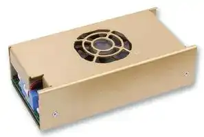
- Screw Terminals Available

-

-

   - U Channel & Cover Fan Formats High Power Density 11.1 W/in3

-

-

   - 5 V Standby & 12 V Fan Outputs Active Current Share

-

   - Remote On/Off

-

AC & DC OK Signals

-

   - -10 ºC to +70 ºC Operation

-

Level B Conducted Emissions

The MFA350 has been designed with multiple mechanical options to facilitate its integration into a wide range of applications. Designers of these systems demand higher power from AC-DC units in industry-standard formats as processing power and functionality grows within tight space constraints. The MFA350 delivers over 350 W across the full universal AC input range from an industry-standard 3.2 x 6.8 inch (81.3 x 172.7 mm) footprint. It is 1.5 inches (38.1 mm) high and achieves 11.1 Watts per cubic inch power density without compromising performance or functionality.

With efficiency up to 88% at full load, the MFA350 operates up to 50 °C ambient and up to 70 °C ambient with derating. The main output is 12, 24 or 48 VDC but each power supply also has a 5 V, 0.3 A standby output and a 12 V, 1A output for powering fans. The unit incorporates a fully featured signal set including AC OK/DC OK, remote on/off and active current sharing.

xppower.com

## Models and Ratings

|Output Voltage<br>V1|Maximum Output<br>Current|Fan Output(2)<br>V2|Standby Supply<br>V3|Max Power<br>13 CFM Airflow|Model Number (1)|
|---|---|---|---|---|---|
|12.0 VDC|29.0 A|12 V/1 A|5 V/0.3 A|361 W|MFA350PS12|
|24.0 VDC|14.5 A|12 V/1 A|5 V/0.3 A|361 W|MFA350PS24|
|48.0 VDC|7.3 A|12 V/1 A|5 V/0.3 A|364 W|MFA350PS48|


## **Notes**

1. Units supplied with AMP/TE connections for J1 & J2 as standard. Add suffix ‘-S’ to model number to replace with screw terminals. Add suffix ‘-TF’ for covered version with top fan and suffix ‘-EF’ for covered version with end fan. Example:- MFA350PS12-STF, 12 V unit fitted with screw terminals and top fan. 2. Not available for -TF & -EF versions.

## Input Characteristics

|Characteristic|Minimum|Typical|Maximum|Units|Notes & Conditions|
|---|---|---|---|---|---|
|Input Voltage - Operating|85||264|VAC|Derate output power 10% < 90 VAC|
|Input Frequency|47|50/60|63|Hz||
|Power Factor||>0.9|||EN61000-3-2 class A|
||||||EN61000-3-2 class C for loads ≥20%|
|Input Current - No Load||100||mA||
|Input Current - Full Load||3.6/1.8||A|115/230 VAC|
|Inrush Current|||60|A|230 VAC cold start|
|Earth Leakage Current||1||mA|230 VAC/50 Hz|
|Input Protection|T6.3A/250 V internal fuse in line|||||


## Output Characteristics

|Characteristic|Minimum|Typical|Maximum|Units|Notes & Conditions|
|---|---|---|---|---|---|
|Output Voltage - V1|12||48|VDC|See Models and Ratings table|
|Initial Set Accuracy|||±1 (V1), ±5 (V2) & ±3 (V3)|%||
|Output Voltage Adjustment|±10|||%||
|Minimum Load|0||||No minimum load required|
|Start Up Delay||1|2|s|90 VAC full load (see fig. 1)|
|Hold Up Time|16|20||ms|90 VAC full load (see fig. 2 & 3)|
|Drift|||±0.2|%|After 20 min warm up|
|Line Regulation|||±0.5(V1), ±3 (V2) & ±3 (V3)|%||
|Load Regulation|||±1 (V1), ±5 (V2) & ±3 (V3)|%|0-100% load. V2 10-100% load|
|Transient Response - V1|||4|%|Recovery within 1% in less than 500 µs<br>for a 50-75% and 75-50% load step|
|Over/Undershoot - V1|||1|%|(see fig. 4)|
|Ripple & Noise|||1 (V1 & V3) & 2 (V2)|% pk-pk|20 MHz bandwidth (see fig. 6 & 7)|
|Overvoltage Protection|115||140|%|Vnom DC. Output 1 only, recycle input to reset|
|Overload Protection|110||140|% I nom|Output 1 only, auto reset (see fig. 5)|
|Short Circuit Protection|||||Continuous|
|Temperature Coefficient|||0.05|%/˚C||
|Overtemperature Protection||75||°C|Thermal sensor under PCB|


2

xppower.com

## Start Up Delay From AC Turn On

**==> picture [133 x 143] intentionally omitted <==**

**----- Start of picture text -----**<br>
AC<br>Figure 1<br>Example of start up all outputs<br>V1<br>V2<br>V3<br>**----- End of picture text -----**<br>


## Hold Up Time From Loss of AC

**==> picture [133 x 253] intentionally omitted <==**

**----- Start of picture text -----**<br>
AC<br>Figure 2<br>V1 hold up at full load with<br>V1<br>90 VAC input (26.8 ms)<br>AC<br>V1<br>Figure 3 V2<br>Full load 90 VAC input<br>V3<br>**----- End of picture text -----**<br>


3

xppower.com

## Output Overshoot

Figure 4 Typical Output Overshoot (MFA350PS12)

## Output Overload Characteristic

Figure 5

**==> picture [293 x 158] intentionally omitted <==**

**----- Start of picture text -----**<br>
Over Current Profile of MFA350PS12<br>14<br>12<br>10<br>8<br>6<br>4<br>2<br>0<br>0 5 10 15 20 25 30 35 40 45<br>Output Current (A)<br>Output Volts (V)<br>**----- End of picture text -----**<br>


4

xppower.com

## Output Ripple & Noise

Figure 6 V1 MFA350PS12 (full load) 80 mV pk-pk ripple. 20 MHz BW

Figure 7 V1 MFA350PS48 (full load) 150 mV pk-pk ripple. 20 MHz BW

5

xppower.com

## XxxxxxxxxxGeneral Specifications

|Characteristic|Minimum<br>Typical|Maximum|Units|Notes & Conditions|
|---|---|---|---|---|
|Efficiency|86||%|Full load (see fig. 8 & 9)|
|Isolation: Input to Output|3000||VAC||
|Input to Ground|1500||VAC||
|Output to Ground|100||VDC||
|Switching Frequency: PFC|62||kHz||
|Main Converter|157||kHz||
|Power Density||11.1|W/in3||
|Mean Time Between Failure|460||kHrs|MIL-HDBK-217F, Notice 2<br>+25 °C GB|
|Weight||1.35 (612)|lb (g)||
||||||
|Characteristic|Notes & Conditions||||
|Signals|||||
|AC OK/Powerfail|Open collector referenced to output 0V, transistor normally off when AC is good (see fig. 10, 16, 17 & 18)<br>AC OK: Provides ≥5 ms warning of loss of output from AC failure||||
|DC OK|Open collector referenced to 0 V, transistor normally off when DC is good (see fig. 11, 19 & 20).<br>Provides warning of DC output failure||Open collector referenced to 0 V, transistor normally off when DC is good (see fig. 11, 19 & 20).||
|Remote On/Off (Inhibit/Enable)|Remotely switches outputs off, can also be configured as enable (see fig.12)||Remotely switches outputs off, can also be configured as enable (see fig.12)||
|Current Share|Up to 3 supplies can be connected in parallel. Output current is shared within 10% at full load. Derate overall<br>output current to 90% when used in parallel (see fig.13, 14 & 15)||||
|Remote Sense|Compensates for 0.5 V total voltage drop||||


## Efficiency Versus Load

**==> picture [257 x 354] intentionally omitted <==**

**----- Start of picture text -----**<br>
88%<br>86%<br>84%<br>82%<br>80%<br>78%<br>76%<br>74%<br>72%<br>0% 20% 40% 60% 80% 100% 120%<br>Load %<br>Figure 8<br>MFA350PS12 @ 230 VAC<br>90%<br>88%<br>86%<br>84%<br>82%<br>80%<br>78%<br>76%<br>74%<br>72%<br>70%<br>68%<br>66%<br>0% 20% 40% 60% 80% 100% 120%<br>Load %<br>=<br>Figure 9<br>[=] MFA350PS48 @ 230 VAC<br>Efficiency %<br>Efficiency %<br>**----- End of picture text -----**<br>


6

xppower.com

## Signals

## AC OK/Power Fail

**==> picture [458 x 606] intentionally omitted <==**

**----- Start of picture text -----**<br>
POWER SUPPLY<br>5 V Standby<br>Pin 9<br>330R<br>Max 12 V 20 mA<br>AC OK Collector<br>Pin 1<br>Figure 10<br>AC OK Emitter  Transistor On (<0.8 V): AC NOT OK<br>Pin 7 Transistor Off (>4.5 V): AC OK<br>5 V Standby<br>Return Pin 10<br>J3 Logic Connector<br>DC OK<br>POWER SUPPLY<br>5 V Standby<br>Pin 9<br>330R<br>Max 12 V 20 mA<br>DC OK Collector<br>Pin 4<br>Figure 11<br>DC OK Emitter  Transistor On (<0.8 V): DC NOT OK<br>Pin 7 Transistor Off (>4.5 V): DC OK<br>5 V Standby<br>Return Pin 10<br>:<br>J3 Logic Connector<br>Remote On/Off (Inhibit) See page 12<br>Mechanical Details<br>for location<br>POWER SUPPLY<br>Internal<br>Vref<br>JP1<br>Figure 12<br>Jumper (JP1) fitted (standard) Pin 2<br>Open or TTL high = PSU On<br>Short circuit or TTL Low  = PSU Off<br>Jumper (JP1) removed<br>Open or TTL high = PSU Off Pin 7<br>Short circuit or TTL Low = PSU On iz<br>J3 Logic Connector<br>**----- End of picture text -----**<br>


7

xppower.com

## XxxxxxxxxxSignals

## Parallel Load & Current Share Connections

**==> picture [555 x 537] intentionally omitted <==**

**----- Start of picture text -----**<br>
PSU 1 PSU 2 PSU 3<br>V1 Output V1 Output V1 Output<br>- + - + - +<br>Current Share Current Share<br>N¢<br>N¢<br>‘\ ¢<br>Figure 13 NN4¢<br>N¢<br>N¢<br>N¢<br>N7<br>N ‘7<br>N ‘7<br>“N La<br>SN”<br>NSEXP<br>- +<br>Load<br>“*<br>Parallel AC OK Connection (DC OK follows same format)<br>er: POWER SUPPLY 1<br>1 5 V Standby  Pin 9<br>330R<br>O<br>AC OK Collector<br>Pin 1<br>yA<br>AC OK Emitter<br>Pin 7<br>5 V Standby<br>Return Pin 10<br>J3 Logic Connector ~_------!O<br>a POWER SUPPLY 2 !|<br>!<br>O<br>OK Collector<br>Pin 1<br>Figure 14<br>OK Emitter<br>Pin 7<br>1<br>!<br>!<br>1<br>J3 Logic Connector ~------!<br>ne<br>POWER SUPPLY 3 1<br>1<br>O<br>AC OK Collector<br>Pin 1<br>Transistor On (<0.8 V): AC NOT OK<br>Transistor Off (>4.5 V): AC OK<br>AC OK Emitter<br>Pin 7<br>1<br>1<br>1<br>J3 Logic Connector _~_--_-!<br>+ Sense - Sense<br>- Sense + Sense<br>- Sense + Sense<br>**----- End of picture text -----**<br>


## Parallel Remote On/Off (Inhibit) Connection

**==> picture [468 x 71] intentionally omitted <==**

**----- Start of picture text -----**<br>
PSU 1 PSU 2 PSU 3<br>Jumper (JP1) fitted<br>Pin 2 Pin 2 Pin 2 Open or TTL high = PSU On<br>Figure 15 Short circuit or TTL Low  = PSU Off<br>Pin 7 Pin 7 Pin 7 Jumper (JP1) removed<br>Open or TTL high = PSU Off<br>Short circuit or TTL Low  = PSU On<br>DTrr J3 LOGIC CONNECTORS —<br>**----- End of picture text -----**<br>


8

xppower.com

## XxxxxxxxxxSignals

**==> picture [28 x 504] intentionally omitted <==**

**----- Start of picture text -----**<br>
AC OK<br>V1<br>V2<br>V3<br>AC OK<br>V1<br>V2<br>V3<br>AC OK<br>V1<br>**----- End of picture text -----**<br>


Figure 16 AC OK signal at AC switch on

**==> picture [112 x 18] intentionally omitted <==**

**----- Start of picture text -----**<br>
Figure 17<br>AC OK signal at AC switch off<br>**----- End of picture text -----**<br>


Figure 18 V1 warning time at AC OK signal 90 VAC full load (MFA350PS12)

9

~~A~~ xppower.com ’ J

## XxxxxxxxxxSignals

Figure 19 DC OK at AC switch on

**==> picture [27 x 118] intentionally omitted <==**

**----- Start of picture text -----**<br>
DC OK<br>V1<br>V2<br>V3<br>**----- End of picture text -----**<br>


**==> picture [138 x 120] intentionally omitted <==**

**----- Start of picture text -----**<br>
DC OK<br>V1<br>Figure 20 V2<br>DC OK at AC switch off<br>V3<br>**----- End of picture text -----**<br>


10

xppower.com

## XxxxxxxxxxEnvironmental

|Characteristic|Minimum|Typical|Maximum|Units|Notes & Conditions|
|---|---|---|---|---|---|
|Operating Temperature|-10||+70|°C|Derate linearly from +50 °C at 2.5%/°C<br>to 50% at 70 °C when forced cooled. See<br>Thermal Considerations.|
|Storage Temperature|-20||+85|°C||
|Cooling|13|||CFM|U Channel Version. -TF & -EF models have<br>integral fan. See Thermal Considerations for<br>U Channel.|
|Humidity|5||95|%RH|Non-condensing|
|Operating Altitude|||3000|m||
|Shock|||||3 x 30 g/11 ms shocks in both +ve & -ve<br>directions along the 3 orthogonal axis,<br>total 18 shocks.|
|Vibration|||||Single axis 10-500 Hz at 2 g x 10 sweeps|


## Electromagnetic Compatibility - Immunity

|Phenomenon|Standard|Test Level|Criteria|Notes & Conditions|
|---|---|---|---|---|
|Harmonic Current|EN61000-3-2|Class A|||
|||Class C||For loads ≥20%|
|EFT|EN61000-4-4|3|A||
|Surges|EN61000-4-5|Installation Class 3|A||
|Conducted|EN61000-4-6|10 V rms|A||
|Dips and Interruptions|EN61000-4-11|30% 10 ms|A||
|||60% 100 ms|B||
|||100% 5000 ms|B||


## Electromagnetic Compatibility - Emissions

|Phenomenon|Standard|Test Level|Criteria|Notes & Conditions|
|---|---|---|---|---|
|Conducted|EN55032|Class B||See fig. 21|
|Radiated|EN55032|Class A|||
|Voltage Fluctuations|EN61000-3-3||||


## Typical EMC Plot

Figure 21

## Safety Agency Approvals

|Safety Agency|Safety Standard|Category|
|---|---|---|
|CB Report|IEC60950-1:2005 Ed 2 / IEC62368-1:2014|Information Technology|
|CSA|CAN/CSA C22.2 No. 62368-1-14|Information Technology|
|UL|UL 62368-1|Information Technology|
|TUV|EN62368-1:2014/A11:2017|Information Technology|
|CE|LVD||


11

xppower.com

## Mechanical Details

## **U Channel Version**

**==> picture [507 x 263] intentionally omitted <==**

**----- Start of picture text -----**<br>
A A<br>8 X M3-0.5 MOUNTING THREAD<br>0.236 (6.0) MAX SCREW PENETRATION<br>TYP ON ALL SIDES OF POWER SUPPLY<br>Max Torque 4.0-5.0 in-lb (0.045 - 0.057 kg-m)<br>6.80<br>| (172.7)<br>2 x 0.60 BR1 FAN<br>(15.3) CONNECTOR V2<br>LOGIC<br>A A CONNECTOR<br>JP1 (ENABLE)<br>VOLTAGE ADJUST<br>C63<br>AIRFLOW<br>(81.3)3.20 = (81.3)3.20 2 x (50.8)2.00 wi C8 a e DC OUTPUTV1(+) i<br>T3 INTERFACE<br>CONNECTOR<br>A L3 A V1(-)<br>pS i, =,= D35 | __ oop<br>INTERFACE CONNAC INPUT 2 x 0.60 2 x 5.80 (147.3)<br> (15.2)<br>1.50<br>(38.1)<br>Ld 2 x  e 1.50 G A A<br>(38.1) |<br>2 x 0.75<br>(19.1)<br>2 x 0.60 2 x 5.80 (147.3)<br>(15.2)<br>2 x 6.80 (172.7)<br>**----- End of picture text -----**<br>


## **Top Fan Version (Suffix TF)**

**==> picture [25 x 5] intentionally omitted <==**

**----- Start of picture text -----**<br>
AIRFLOW<br>**----- End of picture text -----**<br>


**==> picture [342 x 199] intentionally omitted <==**

**----- Start of picture text -----**<br>
0.60<br>(15.20) 5.80 (147.30)<br>0.66<br>(16.80) Logic<br>Connector<br>Voltage<br>2.00 Adjust<br>3.32 (50.80) V1(+)<br>(84.50) Output<br>(84.50)3.32 V1(-) InterfaceConnector<br>4 x M3-0.5 Mounting Thread<br>2.00 0.236 (6.0) Max Screw Penetration bottom side of<br>(50.79) power supply. Max Torque 4.5-5.0 in-lb (0.045-0.057 kg-m)<br>AC Input 6.80 (172.72) 0.80<br>Interface connector (2.02)<br>} ~~ Py<br>2.00<br>(50.79)<br>[- +<br>**----- End of picture text -----**<br>


## **Notes**

1. All dimensions in inches (mm).

2. Tolerance: X.XX = ±0.02 (±0.50), X.XXX = ±0.01 (±0.25)

12

xppower.com

## Mechanical Details

**End Fan Version (Suffix EF)**

**==> picture [383 x 292] intentionally omitted <==**

**----- Start of picture text -----**<br>
8.28 (210.31)<br>__<br>1.75<br>(44.45)<br>| ®<br>0.08 Ps 8.20 (208.28) L E<br>(2.03)<br>7.20 (182.88)<br>0.60 5.80 (147.32) 4.00<br>(15.20) (10.16)<br>0.66<br>(16.84)<br>Logic<br>Connector<br>3.32 1.37 VoltageAdjust<br>(84.47)3.32 (84.48) 2.00 (34.92) AIRFLOW V1(+)<br>(50.80) Output<br>Interface<br>Connector<br>V1(-)<br>5 x M3-0.5 Mounting Thread<br>1.75 (44.45) Interface ConnectorAC Input 0.236 (6.0) Max Screw Penetration bottom side of power supply.Max Torque 4.5-5.0 in-lb (0.045-0.057 kg-m)<br>1.75<br>(44.45)<br>6.80 (172.70)<br>8.20 (208.28)<br>**----- End of picture text -----**<br>


**Notes**

1. All dimensions in inches (mm).

2. Tolerance: X.XX = ±0.02 (±0.50), X.XXX = ±0.01 (±0.25)

## Mechanical Details - Pin Connections

|PIN CONNECTIONS||PIN CONNECTIONS||PIN CONNECTIONS||PIN CONNECTIONS|PIN CONNECTIONS|PIN CONNECTIONS|
|---|---|---|---|---|---|---|---|---|
|AC INPUT J1||DC OUTPUT J2||LOGIC CONNECTOR J3||FAN OUTPUT J4|||
|AMP/TE CONN = 640445-5||AMP/TE CONN = 1-640445-0||JST B10B-PHDSS(LF) (SN)||Molex 22-04-1021|||
|1<br>GND||1<br>+V1||1<br>AC OK||1||-V2|
|3<br>Neutral<br>5<br>Line||2<br>+V1<br>3<br>+V1<br>4<br>+V1||2<br>ROF (Inhibit/Enable)<br>3<br>Current Share<br>4<br>DC OK||2<br>Mating Parts:||+V2|
|Mating Parts:<br>AMP/TE CONN Housing =||5<br>+V1<br>6<br>-V1||5<br>Not used<br>6<br>+Sense||Molex Housing 22-01-1024<br>Contact 08-70-0057|||
|640250-5<br>Contact 350980-1||7<br>-V1||7<br>-Sense|||||
|||8<br>-V1||8<br>Not Used|||||
|Option ‘-S’ screw terminals<br>Phoenix Contact:||9<br>-V1||9<br>5 V Standby V3|||||
|MKDS 1/5-3.81 or similar||10<br>-V1||10<br>5 V Standby Return V3|||||
|accepts 26-16 AWG wire<br>(contacts 2 & 4 removed)||Mating Parts:<br>AMP/TE CONN = 1-640250-0||Mating Parts:<br>JST Housing PHDR-10VS|||||
|Max Torque 1.73 in-lb||Contact 350980-1||Contact SPHD-001T-P0.5|||||
|(0.02 kg-m)||Option ‘-S’ screw terminals|||||||
|||2 x Phoenix Contact:|||||||
|||MKDS 1/5-3.81 or similar accepts|||||||
|||26-16 AWG wire|||||||


Mating Parts: AMP/TE CONN Housing = 640250-5 Contact 350980-1

Max Torque 1.73 in-lb (0.02 kg-m)

13

xppower.com

## Thermal Considerations (U Channel)

In order to ensure correct and reliable operation of the PSU in the most adverse conditions permitted in the end-use equipment, the temperature of the components listed in the table below must not be exceeded. See drawing on page 12 for component locations. Temperature should be monitored

using K type thermocouples placed on the hottest part of the component (out of any direct air flow).

|Component<br>T3<br>BR1<br>D35<br>L3<br>~~—~~|Temperature Measurements (Ambient≤50 ºC)<br>Max Temperature °C<br>90 °C<br>105 °C<br>85 °C<br>90 °C|
|---|---|


## Service Life

The estimated service life of the MFA350 is determined by the cooling arrangements and load conditions experienced in the end application. Due to the uncertain nature of the end application this estimated service life is based on the actual measured temperature of two key capacitors within the product when installed in the end application. The highest of the two component temperatures should be used. The graph below expresses the estimated lifetime for a given component temperature and assumes continuous operation at this temperature.

## Estimated Service Life vs Component Temperature

**==> picture [288 x 150] intentionally omitted <==**

**----- Start of picture text -----**<br>
185000<br>165000<br>145000<br>125000<br>105000<br>85000<br>65000<br>45000<br>25000<br>5000 =z<br>105 95 85 75 65 55<br>C8 & 63 Temperature (°C)<br>Lifetime (Hrs)<br>**----- End of picture text -----**<br>


14

18 Feb 20

- Screw Terminals Available

-

-

   - U Channel & Cover Fan Formats High Power Density 11.1 W/in3

-

-

   - 5 V Standby & 12 V Fan Outputs Active Current Share

-

   - Remote On/Off

-

AC & DC OK Signals

-

   - -10 ºC to +70 ºC Operation

-

Level B Conducted Emissions

The MFA350 has been designed with multiple mechanical options to facilitate its integration into a wide range of applications. Designers of these systems demand higher power from AC-DC units in industry-standard formats as processing power and functionality grows within tight space constraints. The MFA350 delivers over 350 W across the full universal AC input range from an industry-standard 3.2 x 6.8 inch (81.3 x 172.7 mm) footprint. It is 1.5 inches (38.1 mm) high and achieves 11.1 Watts per cubic inch power density without compromising performance or functionality.

With efficiency up to 88% at full load, the MFA350 operates up to 50 °C ambient and up to 70 °C ambient with derating. The main output is 12, 24 or 48 VDC but each power supply also has a 5 V, 0.3 A standby output and a 12 V, 1A output for powering fans. The unit incorporates a fully featured signal set including AC OK/DC OK, remote on/off and active current sharing.

xppower.com

## Models and Ratings

|Output Voltage<br>V1|Maximum Output<br>Current|Fan Output(2)<br>V2|Standby Supply<br>V3|Max Power<br>13 CFM Airflow|Model Number (1)|
|---|---|---|---|---|---|
|12.0 VDC|29.0 A|12 V/1 A|5 V/0.3 A|361 W|MFA350PS12|
|24.0 VDC|14.5 A|12 V/1 A|5 V/0.3 A|361 W|MFA350PS24|
|48.0 VDC|7.3 A|12 V/1 A|5 V/0.3 A|364 W|MFA350PS48|


## **Notes**

1. Units supplied with AMP/TE connections for J1 & J2 as standard. Add suffix ‘-S’ to model number to replace with screw terminals. Add suffix ‘-TF’ for covered version with top fan and suffix ‘-EF’ for covered version with end fan. Example:- MFA350PS12-STF, 12 V unit fitted with screw terminals and top fan. 2. Not available for -TF & -EF versions.

## Input Characteristics

|Characteristic|Minimum|Typical|Maximum|Units|Notes & Conditions|
|---|---|---|---|---|---|
|Input Voltage - Operating|85||264|VAC|Derate output power 10% < 90 VAC|
|Input Frequency|47|50/60|63|Hz||
|Power Factor||>0.9|||EN61000-3-2 class A|
||||||EN61000-3-2 class C for loads ≥20%|
|Input Current - No Load||100||mA||
|Input Current - Full Load||3.6/1.8||A|115/230 VAC|
|Inrush Current|||60|A|230 VAC cold start|
|Earth Leakage Current||1||mA|230 VAC/50 Hz|
|Input Protection|T6.3A/250 V internal fuse in line|||||


## Output Characteristics

|Characteristic|Minimum|Typical|Maximum|Units|Notes & Conditions|
|---|---|---|---|---|---|
|Output Voltage - V1|12||48|VDC|See Models and Ratings table|
|Initial Set Accuracy|||±1 (V1), ±5 (V2) & ±3 (V3)|%||
|Output Voltage Adjustment|±10|||%||
|Minimum Load|0||||No minimum load required|
|Start Up Delay||1|2|s|90 VAC full load (see fig. 1)|
|Hold Up Time|16|20||ms|90 VAC full load (see fig. 2 & 3)|
|Drift|||±0.2|%|After 20 min warm up|
|Line Regulation|||±0.5(V1), ±3 (V2) & ±3 (V3)|%||
|Load Regulation|||±1 (V1), ±5 (V2) & ±3 (V3)|%|0-100% load. V2 10-100% load|
|Transient Response - V1|||4|%|Recovery within 1% in less than 500 µs<br>for a 50-75% and 75-50% load step|
|Over/Undershoot - V1|||1|%|(see fig. 4)|
|Ripple & Noise|||1 (V1 & V3) & 2 (V2)|% pk-pk|20 MHz bandwidth (see fig. 6 & 7)|
|Overvoltage Protection|115||140|%|Vnom DC. Output 1 only, recycle input to reset|
|Overload Protection|110||140|% I nom|Output 1 only, auto reset (see fig. 5)|
|Short Circuit Protection|||||Continuous|
|Temperature Coefficient|||0.05|%/˚C||
|Overtemperature Protection||75||°C|Thermal sensor under PCB|


2

xppower.com

## Start Up Delay From AC Turn On

**==> picture [133 x 143] intentionally omitted <==**

**----- Start of picture text -----**<br>
AC<br>Figure 1<br>Example of start up all outputs<br>V1<br>V2<br>V3<br>**----- End of picture text -----**<br>


## Hold Up Time From Loss of AC

**==> picture [133 x 253] intentionally omitted <==**

**----- Start of picture text -----**<br>
AC<br>Figure 2<br>V1 hold up at full load with<br>V1<br>90 VAC input (26.8 ms)<br>AC<br>V1<br>Figure 3 V2<br>Full load 90 VAC input<br>V3<br>**----- End of picture text -----**<br>


3

xppower.com

## Output Overshoot

Figure 4 Typical Output Overshoot (MFA350PS12)

## Output Overload Characteristic

Figure 5

**==> picture [293 x 158] intentionally omitted <==**

**----- Start of picture text -----**<br>
Over Current Profile of MFA350PS12<br>14<br>12<br>10<br>8<br>6<br>4<br>2<br>0<br>0 5 10 15 20 25 30 35 40 45<br>Output Current (A)<br>Output Volts (V)<br>**----- End of picture text -----**<br>


4

xppower.com

## Output Ripple & Noise

Figure 6 V1 MFA350PS12 (full load) 80 mV pk-pk ripple. 20 MHz BW

Figure 7 V1 MFA350PS48 (full load) 150 mV pk-pk ripple. 20 MHz BW

5

xppower.com

## XxxxxxxxxxGeneral Specifications

|Characteristic|Minimum<br>Typical|Maximum|Units|Notes & Conditions|
|---|---|---|---|---|
|Efficiency|86||%|Full load (see fig. 8 & 9)|
|Isolation: Input to Output|3000||VAC||
|Input to Ground|1500||VAC||
|Output to Ground|100||VDC||
|Switching Frequency: PFC|62||kHz||
|Main Converter|157||kHz||
|Power Density||11.1|W/in3||
|Mean Time Between Failure|460||kHrs|MIL-HDBK-217F, Notice 2<br>+25 °C GB|
|Weight||1.35 (612)|lb (g)||
||||||
|Characteristic|Notes & Conditions||||
|Signals|||||
|AC OK/Powerfail|Open collector referenced to output 0V, transistor normally off when AC is good (see fig. 10, 16, 17 & 18)<br>AC OK: Provides ≥5 ms warning of loss of output from AC failure||||
|DC OK|Open collector referenced to 0 V, transistor normally off when DC is good (see fig. 11, 19 & 20).<br>Provides warning of DC output failure||Open collector referenced to 0 V, transistor normally off when DC is good (see fig. 11, 19 & 20).||
|Remote On/Off (Inhibit/Enable)|Remotely switches outputs off, can also be configured as enable (see fig.12)||Remotely switches outputs off, can also be configured as enable (see fig.12)||
|Current Share|Up to 3 supplies can be connected in parallel. Output current is shared within 10% at full load. Derate overall<br>output current to 90% when used in parallel (see fig.13, 14 & 15)||||
|Remote Sense|Compensates for 0.5 V total voltage drop||||


## Efficiency Versus Load

**==> picture [257 x 354] intentionally omitted <==**

**----- Start of picture text -----**<br>
88%<br>86%<br>84%<br>82%<br>80%<br>78%<br>76%<br>74%<br>72%<br>0% 20% 40% 60% 80% 100% 120%<br>Load %<br>Figure 8<br>MFA350PS12 @ 230 VAC<br>90%<br>88%<br>86%<br>84%<br>82%<br>80%<br>78%<br>76%<br>74%<br>72%<br>70%<br>68%<br>66%<br>0% 20% 40% 60% 80% 100% 120%<br>Load %<br>=<br>Figure 9<br>[=] MFA350PS48 @ 230 VAC<br>Efficiency %<br>Efficiency %<br>**----- End of picture text -----**<br>


6

xppower.com

## Signals

## AC OK/Power Fail

**==> picture [458 x 606] intentionally omitted <==**

**----- Start of picture text -----**<br>
POWER SUPPLY<br>5 V Standby<br>Pin 9<br>330R<br>Max 12 V 20 mA<br>AC OK Collector<br>Pin 1<br>Figure 10<br>AC OK Emitter  Transistor On (<0.8 V): AC NOT OK<br>Pin 7 Transistor Off (>4.5 V): AC OK<br>5 V Standby<br>Return Pin 10<br>J3 Logic Connector<br>DC OK<br>POWER SUPPLY<br>5 V Standby<br>Pin 9<br>330R<br>Max 12 V 20 mA<br>DC OK Collector<br>Pin 4<br>Figure 11<br>DC OK Emitter  Transistor On (<0.8 V): DC NOT OK<br>Pin 7 Transistor Off (>4.5 V): DC OK<br>5 V Standby<br>Return Pin 10<br>:<br>J3 Logic Connector<br>Remote On/Off (Inhibit) See page 12<br>Mechanical Details<br>for location<br>POWER SUPPLY<br>Internal<br>Vref<br>JP1<br>Figure 12<br>Jumper (JP1) fitted (standard) Pin 2<br>Open or TTL high = PSU On<br>Short circuit or TTL Low  = PSU Off<br>Jumper (JP1) removed<br>Open or TTL high = PSU Off Pin 7<br>Short circuit or TTL Low = PSU On iz<br>J3 Logic Connector<br>**----- End of picture text -----**<br>


7

xppower.com

## XxxxxxxxxxSignals

## Parallel Load & Current Share Connections

**==> picture [555 x 537] intentionally omitted <==**

**----- Start of picture text -----**<br>
PSU 1 PSU 2 PSU 3<br>V1 Output V1 Output V1 Output<br>- + - + - +<br>Current Share Current Share<br>N¢<br>N¢<br>‘\ ¢<br>Figure 13 NN4¢<br>N¢<br>N¢<br>N¢<br>N7<br>N ‘7<br>N ‘7<br>“N La<br>SN”<br>NSEXP<br>- +<br>Load<br>“*<br>Parallel AC OK Connection (DC OK follows same format)<br>er: POWER SUPPLY 1<br>1 5 V Standby  Pin 9<br>330R<br>O<br>AC OK Collector<br>Pin 1<br>yA<br>AC OK Emitter<br>Pin 7<br>5 V Standby<br>Return Pin 10<br>J3 Logic Connector ~_------!O<br>a POWER SUPPLY 2 !|<br>!<br>O<br>OK Collector<br>Pin 1<br>Figure 14<br>OK Emitter<br>Pin 7<br>1<br>!<br>!<br>1<br>J3 Logic Connector ~------!<br>ne<br>POWER SUPPLY 3 1<br>1<br>O<br>AC OK Collector<br>Pin 1<br>Transistor On (<0.8 V): AC NOT OK<br>Transistor Off (>4.5 V): AC OK<br>AC OK Emitter<br>Pin 7<br>1<br>1<br>1<br>J3 Logic Connector _~_--_-!<br>+ Sense - Sense<br>- Sense + Sense<br>- Sense + Sense<br>**----- End of picture text -----**<br>


## Parallel Remote On/Off (Inhibit) Connection

**==> picture [468 x 71] intentionally omitted <==**

**----- Start of picture text -----**<br>
PSU 1 PSU 2 PSU 3<br>Jumper (JP1) fitted<br>Pin 2 Pin 2 Pin 2 Open or TTL high = PSU On<br>Figure 15 Short circuit or TTL Low  = PSU Off<br>Pin 7 Pin 7 Pin 7 Jumper (JP1) removed<br>Open or TTL high = PSU Off<br>Short circuit or TTL Low  = PSU On<br>DTrr J3 LOGIC CONNECTORS —<br>**----- End of picture text -----**<br>


8

xppower.com

## XxxxxxxxxxSignals

**==> picture [28 x 504] intentionally omitted <==**

**----- Start of picture text -----**<br>
AC OK<br>V1<br>V2<br>V3<br>AC OK<br>V1<br>V2<br>V3<br>AC OK<br>V1<br>**----- End of picture text -----**<br>


Figure 16 AC OK signal at AC switch on

**==> picture [112 x 18] intentionally omitted <==**

**----- Start of picture text -----**<br>
Figure 17<br>AC OK signal at AC switch off<br>**----- End of picture text -----**<br>


Figure 18 V1 warning time at AC OK signal 90 VAC full load (MFA350PS12)

9

~~A~~ xppower.com ’ J

## XxxxxxxxxxSignals

Figure 19 DC OK at AC switch on

**==> picture [27 x 118] intentionally omitted <==**

**----- Start of picture text -----**<br>
DC OK<br>V1<br>V2<br>V3<br>**----- End of picture text -----**<br>


**==> picture [138 x 120] intentionally omitted <==**

**----- Start of picture text -----**<br>
DC OK<br>V1<br>Figure 20 V2<br>DC OK at AC switch off<br>V3<br>**----- End of picture text -----**<br>


10

xppower.com

## XxxxxxxxxxEnvironmental

|Characteristic|Minimum|Typical|Maximum|Units|Notes & Conditions|
|---|---|---|---|---|---|
|Operating Temperature|-10||+70|°C|Derate linearly from +50 °C at 2.5%/°C<br>to 50% at 70 °C when forced cooled. See<br>Thermal Considerations.|
|Storage Temperature|-20||+85|°C||
|Cooling|13|||CFM|U Channel Version. -TF & -EF models have<br>integral fan. See Thermal Considerations for<br>U Channel.|
|Humidity|5||95|%RH|Non-condensing|
|Operating Altitude|||3000|m||
|Shock|||||3 x 30 g/11 ms shocks in both +ve & -ve<br>directions along the 3 orthogonal axis,<br>total 18 shocks.|
|Vibration|||||Single axis 10-500 Hz at 2 g x 10 sweeps|


## Electromagnetic Compatibility - Immunity

|Phenomenon|Standard|Test Level|Criteria|Notes & Conditions|
|---|---|---|---|---|
|Harmonic Current|EN61000-3-2|Class A|||
|||Class C||For loads ≥20%|
|EFT|EN61000-4-4|3|A||
|Surges|EN61000-4-5|Installation Class 3|A||
|Conducted|EN61000-4-6|10 V rms|A||
|Dips and Interruptions|EN61000-4-11|30% 10 ms|A||
|||60% 100 ms|B||
|||100% 5000 ms|B||


## Electromagnetic Compatibility - Emissions

|Phenomenon|Standard|Test Level|Criteria|Notes & Conditions|
|---|---|---|---|---|
|Conducted|EN55032|Class B||See fig. 21|
|Radiated|EN55032|Class A|||
|Voltage Fluctuations|EN61000-3-3||||


## Typical EMC Plot

Figure 21

## Safety Agency Approvals

|Safety Agency|Safety Standard|Category|
|---|---|---|
|CB Report|IEC60950-1:2005 Ed 2 / IEC62368-1:2014|Information Technology|
|UL/CSA|UL 62368-1 / CAN/CSA C22.2 No. 62368-1-14|Information Technology|
|TUV|EN62368-1:2014/A11:2017|Information Technology|
|CE|LVD||


11

xppower.com

## Mechanical Details

## **U Channel Version**

**==> picture [507 x 263] intentionally omitted <==**

**----- Start of picture text -----**<br>
A A<br>8 X M3-0.5 MOUNTING THREAD<br>0.236 (6.0) MAX SCREW PENETRATION<br>TYP ON ALL SIDES OF POWER SUPPLY<br>Max Torque 4.0-5.0 in-lb (0.045 - 0.057 kg-m)<br>6.80<br>| (172.7)<br>2 x 0.60 BR1 FAN<br>(15.3) CONNECTOR V2<br>LOGIC<br>A A CONNECTOR<br>JP1 (ENABLE)<br>VOLTAGE ADJUST<br>C63<br>AIRFLOW<br>(81.3)3.20 = (81.3)3.20 2 x (50.8)2.00 wi C8 a e DC OUTPUTV1(+) i<br>T3 INTERFACE<br>CONNECTOR<br>A L3 A V1(-)<br>pS i, =,= D35 | __ oop<br>INTERFACE CONNAC INPUT 2 x 0.60 2 x 5.80 (147.3)<br> (15.2)<br>1.50<br>(38.1)<br>Ld 2 x  e 1.50 G A A<br>(38.1) |<br>2 x 0.75<br>(19.1)<br>2 x 0.60 2 x 5.80 (147.3)<br>(15.2)<br>2 x 6.80 (172.7)<br>**----- End of picture text -----**<br>


## **Top Fan Version (Suffix TF)**

**==> picture [25 x 5] intentionally omitted <==**

**----- Start of picture text -----**<br>
AIRFLOW<br>**----- End of picture text -----**<br>


**==> picture [342 x 199] intentionally omitted <==**

**----- Start of picture text -----**<br>
0.60<br>(15.20) 5.80 (147.30)<br>0.66<br>(16.80) Logic<br>Connector<br>Voltage<br>2.00 Adjust<br>3.32 (50.80) V1(+)<br>(84.50) Output<br>(84.50)3.32 V1(-) InterfaceConnector<br>4 x M3-0.5 Mounting Thread<br>2.00 0.236 (6.0) Max Screw Penetration bottom side of<br>(50.79) power supply. Max Torque 4.5-5.0 in-lb (0.045-0.057 kg-m)<br>AC Input 6.80 (172.72) 0.80<br>Interface connector (2.02)<br>} ~~ Py<br>2.00<br>(50.79)<br>[- +<br>**----- End of picture text -----**<br>


## **Notes**

1. All dimensions in inches (mm).

2. Tolerance: X.XX = ±0.02 (±0.50), X.XXX = ±0.01 (±0.25)

12

xppower.com

## Mechanical Details

**End Fan Version (Suffix EF)**

**==> picture [383 x 292] intentionally omitted <==**

**----- Start of picture text -----**<br>
8.28 (210.31)<br>__<br>1.75<br>(44.45)<br>| ®<br>0.08 Ps 8.20 (208.28) L E<br>(2.03)<br>7.20 (182.88)<br>0.60 5.80 (147.32) 4.00<br>(15.20) (10.16)<br>0.66<br>(16.84)<br>Logic<br>Connector<br>3.32 1.37 VoltageAdjust<br>(84.47)3.32 (84.48) 2.00 (34.92) AIRFLOW V1(+)<br>(50.80) Output<br>Interface<br>Connector<br>V1(-)<br>5 x M3-0.5 Mounting Thread<br>1.75 (44.45) Interface ConnectorAC Input 0.236 (6.0) Max Screw Penetration bottom side of power supply.Max Torque 4.5-5.0 in-lb (0.045-0.057 kg-m)<br>1.75<br>(44.45)<br>6.80 (172.70)<br>8.20 (208.28)<br>**----- End of picture text -----**<br>


**Notes**

1. All dimensions in inches (mm).

2. Tolerance: X.XX = ±0.02 (±0.50), X.XXX = ±0.01 (±0.25)

## Mechanical Details - Pin Connections

|PIN CONNECTIONS||PIN CONNECTIONS||PIN CONNECTIONS||PIN CONNECTIONS|PIN CONNECTIONS|PIN CONNECTIONS|
|---|---|---|---|---|---|---|---|---|
|AC INPUT J1||DC OUTPUT J2||LOGIC CONNECTOR J3||FAN OUTPUT J4|||
|AMP/TE CONN = 640445-5||AMP/TE CONN = 1-640445-0||JST B10B-PHDSS(LF) (SN)||Molex 22-04-1021|||
|1<br>GND||1<br>+V1||1<br>AC OK||1||-V2|
|3<br>Neutral<br>5<br>Line||2<br>+V1<br>3<br>+V1<br>4<br>+V1||2<br>ROF (Inhibit/Enable)<br>3<br>Current Share<br>4<br>DC OK||2<br>Mating Parts:||+V2|
|Mating Parts:<br>AMP/TE CONN Housing =||5<br>+V1<br>6<br>-V1||5<br>Not used<br>6<br>+Sense||Molex Housing 22-01-1024<br>Contact 08-70-0057|||
|640250-5<br>Contact 350980-1||7<br>-V1||7<br>-Sense|||||
|||8<br>-V1||8<br>Not Used|||||
|Option ‘-S’ screw terminals<br>Phoenix Contact:||9<br>-V1||9<br>5 V Standby V3|||||
|MKDS 1/5-3.81 or similar||10<br>-V1||10<br>5 V Standby Return V3|||||
|accepts 26-16 AWG wire<br>(contacts 2 & 4 removed)||Mating Parts:<br>AMP/TE CONN = 1-640250-0||Mating Parts:<br>JST Housing PHDR-10VS|||||
|Max Torque 1.73 in-lb||Contact 350980-1||Contact SPHD-001T-P0.5|||||
|(0.02 kg-m)||Option ‘-S’ screw terminals|||||||
|||2 x Phoenix Contact:|||||||
|||MKDS 1/5-3.81 or similar accepts|||||||
|||26-16 AWG wire|||||||


Mating Parts: AMP/TE CONN Housing = 640250-5 Contact 350980-1

Max Torque 1.73 in-lb (0.02 kg-m)

13

xppower.com

## Thermal Considerations (U Channel)

In order to ensure correct and reliable operation of the PSU in the most adverse conditions permitted in the end-use equipment, the temperature of the components listed in the table below must not be exceeded. See drawing on page 12 for component locations. Temperature should be monitored

using K type thermocouples placed on the hottest part of the component (out of any direct air flow).

|Component<br>T3<br>BR1<br>D35<br>L3<br>~~—~~|Temperature Measurements (Ambient≤50 ºC)<br>Max Temperature °C<br>90 °C<br>105 °C<br>85 °C<br>90 °C|
|---|---|


## Service Life

The estimated service life of the MFA350 is determined by the cooling arrangements and load conditions experienced in the end application. Due to the uncertain nature of the end application this estimated service life is based on the actual measured temperature of two key capacitors within the product when installed in the end application. The highest of the two component temperatures should be used. The graph below expresses the estimated lifetime for a given component temperature and assumes continuous operation at this temperature.

## Estimated Service Life vs Component Temperature

**==> picture [288 x 150] intentionally omitted <==**

**----- Start of picture text -----**<br>
185000<br>165000<br>145000<br>125000<br>105000<br>85000<br>65000<br>45000<br>25000<br>5000 =z<br>105 95 85 75 65 55<br>C8 & 63 Temperature (°C)<br>Lifetime (Hrs)<br>**----- End of picture text -----**<br>


14

05 March 20
Updated at June 10, 2026
XP Power is a globally recognized leader in the design and manufacture of critical power solutions for the electronics industry. With a steadfast commitment to total quality and in-house engineering expertise, the company delivers highly reliable components that support complex applications across the industrial, healthcare, and technology sectors. Their extensive manufacturing capabilities provide engineers with a broad and dependable source for innovative power products. Our extensive portfolio of XP Power components is heavily focused on robust power and line protection. The core of this offering features a vast selection of high-performance AC/DC converters, designed to meet the rigorous efficiency and footprint demands of modern electronic systems. Complementing these are numerous reliable DC/DC converters, providing versatile options for precise voltage regulation and seamless system integration. Beyond their primary power conversion ranges, XP Power manufactures specialized components to address specific design challenges. Our selection includes essential passive components, such as power line filters for effective EMC and RFI suppression, ensuring signal integrity and strict regulatory compliance. Additionally, we provide dedicated AC/DC LED power supplies tailored for reliable, long-lasting performance in advanced commercial and industrial lighting applications.
About Novapart
Novapart is a B2B electronic component broker specialising in stock shortages and cost reduction. We source hard-to-find parts and identify compliant alternatives across a catalogue of 410,000+ components from 500+ manufacturers.
Learn more →Stock Shortage Specialist
When a component is unavailable, discontinued or has an unacceptable lead time, we tap into our network of vetted European and Asian distributors to source what you need — without compromising on quality or traceability.
Request a quote →Compliant Alternatives
We identify pin-to-pin, electrically equivalent substitutes that meet the same certifications (RoHS, AEC-Q100, REACH) as your original specification — validated against datasheets, not just part numbers. Often at a lower cost.
BOM Analysis service →