
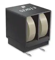


MF-SD013/250-2
Resettable Fuse, PPTC, 3425 (8763 Metric), MF-SD/250, 60 VDC, 130 mA, 260 mA, 2.5 s
- Manufacturer: BOURNS
- Product type: Surface Mount PPTCs
- Thermistor Mounting:SMD; Product Range:MF-SD/250 Series; Holding Current:130mA; Tripping Current:260mA; Voltage Rating:60V; Operating Temperature Min:-40°C; Operating Temperature Max:85°C; Aut
- SVHC: No SVHC (04-Feb-2026)
- Time to Trip: 2.5s
- Trip Current: 260mA
- Product Range: MF-SD/250
- Voltage Rating: 60VDC
- Holding Current: 130mA
- PPTC Case Style: 3425 (8763 Metric)
- Current Rating Max: 3A
- Operating Temperature Max: 85°C
- Operating Temperature Min: -40°C
- Automotive Qualification Standard: -
| Delivery and price | |
|---|---|
| Units per pack | 4000 |
| Price | 0.52 € |
| Current stock | 10+ |
| Lead time | 30 days |
**Features Applications** n Tip & ring line protection with two devices Used as a secondary overcurrent protection in one surface mount package device in: n High voltage surge capabilities n Customer Premise Equipment (CPE) n Assists in meeting ITU-T K.20/K.21/K.45 n Central Office (CO) specifications as well as Telcordia GR-1089 n Subscriber Line Interface Cards (SLIC) intra-building n RoHS compliant* n Agency recognition: **MF-SD/250 Series - Telecom PTC Resettable Fuses** ~~eT~~ ~~**Electrical Characteristics**~~ **Max. Max. Initial 1 Hour (R1) Nominal Time Tripped Model Operating Voltage Interrupt Ratings Ihold Itrip Resistance Resistance*Post-Trip to Trip DissiPower pation Volts Amps Amperes at 23 °C at 23 Ohms °C at 23 Ohms °C at 23 Amps °C Seconds at 23 °C at 23 Watts °C Volts (V) (A)** Hold Trip Min. Max. Max. Typ. MF-SD013/250 60 250 3.0 0.13 0.26 2.0 7.0 10.0 1 2.5 1.5 ~~i...—~~ * R1 value is measured 24 hours post reflow. Resistance matched in housing:  1.0 ohm measured 24 hours after reflow installation.

## ~~**Environmental Characteristics**~~

Operating Temperature .................................... -45 °C to +85 °C Maximum Device Surface Temperature in Tripped State ............................................ 125 °C Passive Aging .................................................. +85 °C, 1000 hours ................................................±15 % typical resistance change Humidity Aging................................................. +85 °C, 85 % R.H. 1000 hours ..............................±15 % typical resistance change Thermal Shock ................................................ MIL-STD-202F, Method 107G, ...............................±15 % typical resistance change +125 °C to -55 °C,10 times ±15 % typical resistance change Solvent Resistance .......................................... MIL-STD-202, Method 215B ..................................No change Lead Solderability ............................................ ANSI/J-STD-002 Flammability .................................................... IEC 695-2-2 ...........................................................No Flame for 60 secs. Vibration .......................................................... MIL-STD-883C, Method 2007.1, Condition A ........No change

## ~~**Test Procedures And Requirements For Model MF-SD/250 Series**~~

**Test Test Conditions Accept/Reject Criteria** Visual/Mech. .................................................... Verify dimensions and materials .......................Per MF physical description Resistance ....................................................... In still air @ 23 °C .............................................Rmin ≤ R ≤ Rmax Time to Trip ...................................................... At specified current, Vmax, 23 °C .....................T ≤ max. time to trip (seconds) Hold Current .................................................... 30 min. at Ihold .................................................No trip **Primary Test Test Conditions Protection** Mains Power Contact - ITU-T K.20, K.21 ........ 230 V rms, 10 ohms, t = 15 min. .......................None Power Induction - ITU-T K.20, K.21 ................. 600V rms, 600 ohms, t = 0.2 seconds ..............None Power Induction - ITU-T K.20, K.21 ................. 600 V rms, 600 ohms, t = 1 second. .................GDT Lightning Surge - ITU-T K.20, K.21 ................. 1.5 KV, 10/700 μs .............................................None Lightning Surge ............................................... 4.0 KV, 10/700 μs .............................................GDT

UL File Number ...........................................E 174545S

~~**Thermal Derating Chart -Ihold (Amps)**~~ **Ambient Operating Temperature Model -40 °C -20 °C 0 °C 23 °C 40 °C 50 °C 60 °C 70 °C 85 °C** MF-SD013/250 0.21 0.18 0.16 0.13 0.10 0.09 0.08 0.07 0.05 ~~pr~~

*RoHS Directive 2002/95/EC Jan. 27, 2003 including annex and RoHS Recast 2011/65/EU June 8, 2011. Specifications are subject to change without notice.

The device characteristics and parameters in this data sheet can and do vary in different applications and actual device performance may vary over time. Users should verify actual device performance in their specific applications.

## **MF-SD/250 Series - Telecom PTC Resettable Fuses**

## ~~**Product Dimensions**~~

**==> picture [313 x 370] intentionally omitted <==**

**----- Start of picture text -----**<br>
8.90<br>(.350)  [MAX.]<br>10.2 MM<br>(402) DIMENSIONS:<br>MAX. (INCHES)<br>2.4 0.5 7.2<br>(.094)3.9 2 PLCS.(.020) (.283) MAX.<br>(.154)<br>Packaging:  TAPE & REEL = 400 pcs. per reel<br>Typical Time to Trip at 23 °C<br>1000<br>100<br>10<br>1<br>0.1<br>0.01<br>0 0.5 1 1.5 2 2.5 3<br>Fault Current  (Amps)<br>Time to Trip (Seconds)<br>**----- End of picture text -----**<br>


## ~~**Solder Refow Recommendations**~~

## **Solder reflow:**

**==> picture [318 x 117] intentionally omitted <==**

**----- Start of picture text -----**<br>
300250 Preheating Soldering Cooling • Recommended reflow methods: IR,   vapor phase oven, hot air oven. vapor phase oven, hot air oven.<br>200 • Devices are not designed to be<br> wave soldered to the bottom side<br>150  of the board.<br>100 • Gluing the devices is not<br> recommended.<br>50 • Recommended maximum paste<br>0  thickness is 0.25  mm (.010 inch).<br>160–220 10–20 120 • Devices can be cleaned using   standard industry methods and<br> solvents.<br>Time (seconds)<br>Note:<br>Temperature (°C)<br>**----- End of picture text -----**<br>


- Recommended reflow methods: IR,   vapor phase oven, hot air oven. vapor phase oven, hot air oven. • Devices are not designed to be wave soldered to the bottom side of the board.

- Recommended maximum paste thickness is 0.25  mm (.010 inch).

## ~~**Recommended Pad Layout**~~

**==> picture [156 x 119] intentionally omitted <==**

**----- Start of picture text -----**<br>
7.2<br>(.283)<br>MAX.<br>1<br>MAX.<br>8.90 2<br>6.3<br>(.350)<br>3 (.2 48)<br>3.9<br>(.154)<br>4<br>2.4<br>3.2 (.094)<br>8.2 (.126) 2.0<br>(.323) (.079)<br>**----- End of picture text -----**<br>


## ~~**Schematic**~~

**==> picture [167 x 152] intentionally omitted <==**

**----- Start of picture text -----**<br>
1 2<br>3 4<br>Typical Part Marking<br>MANUFACTURER'S<br>TRADEMARK<br>PART<br>SD013 IDENTIFICATION<br>**----- End of picture text -----**<br>


## ~~**How to Order**~~

**==> picture [85 x 7] intentionally omitted <==**

**----- Start of picture text -----**<br>
MF - SD 013/250 -  2<br>**----- End of picture text -----**<br>


Multifuse[®] Product Designator Series SD = Surface Mount Dual Package Hold Current, Ihold 013 (0.13 Amps)

Max. Interrupt Voltage, V 250 = 250 Volts Packaging - 2 = Tape and Reel* *Packaged per EIA481-2

- If reflow temperatures exceed the recommended profile, devices may not meet the performance requirements. **Rework:**

- A device should not be reworked.

Specifications are subject to change without notice. The device characteristics and parameters in this data sheet can and do vary in different applications and actual device performance may vary over time. Users should verify actual device performance in their specific applications.

## **MF-SD/250 Series - Telecom PTC Resettable Fuses**

## ~~**Storage Recommendations**~~

The recommended long term storage conditions for Multifuse[®] Polymer PTC devices are 40 °C maximum and 70 % RH maximum. All devices should remain in the original sealed packaging prior to use. Devices may not conform with data sheet specifications if these storage recommendations are exceeded. Devices stored in this manner have an indefinite shelf life.

## ~~**Packaging Dimensions**~~

|**Tape Dimensions**|**Tape Dimensions**|**Tape Dimensions**|**Tape Dimensions**|**Tape Dimensions**|**Tape Dimensions**|**Tape Dimensions**|**Tape Dimensions**|**Tape Dimensions**|**Tape Dimensions**|**MF**<br>|**MF**<br>|**MF**<br>|**MF**<br>|**MF**<br>|**MF**<br>|**MF**<br>|**MF**<br>|**MF**<br>|**-SD/250 Series**<br>**per EIA 481-2**|**-SD/250 Series**<br>**per EIA 481-2**|**-SD/250 Series**<br>**per EIA 481-2**|**-SD/250 Series**<br>**per EIA 481-2**|**-SD/250 Series**<br>**per EIA 481-2**|**-SD/250 Series**<br>**per EIA 481-2**|
|---|---|---|---|---|---|---|---|---|---|---|---|---|---|---|---|---|---|---|---|---|---|---|---|---|
|W||||||||||(|||||||||24.0 ± 0.5<br>0.945 ± 0.020)||||||
|P0|||||||||||||||||||4.0<br>(0.157)||||||
|P|||||||||||||||||||16.0<br>(0.630)||||||
|P2|||||||||||||||||||2.0<br>(0.079)||||||
|A0||||||||||(|||||||||7.5±0.2<br>0.295 ± 0.008)||||||
|B0||||||||||(|||||||||9.0 ± 0.2<br>0.354 ± 0.008)||||||
|D|||||||||||||||||||1.5<br>(0.059)||||||
|F|||||||||||||||||||11.5<br>||||||
||||||||||||||||||||(0.453)||||||
|E|||||||||||||||||||1.7||5||||
||||||||||||||||||||(|0.0|69)||||
|t||||||||||(|||||||||0.5 ±||0.15<br>0.006)||||
|||||||||||||||||||(|||||||
||||||||||||||||||||.02|±|||||
|K0||||||||||||||||||(|10|.0 ±|0.|2|||
||||||||||||||||||||<br>0.39|<br>4 ±|<br> ~~0.0~~|<br>|||
|Leader min.||||||||||||||||||||39|0||||
||||||||||||||||||||<br>(15.||||||
|Trailer min.|||||||||||||||||||160<br>(630)||||||
||||||||||||||||||||.||||||


**==> picture [504 x 165] intentionally omitted <==**

**----- Start of picture text -----**<br>
D P2 P0 E T -0.4<br>(-.016)<br>F 330 -2/+0<br>(12.99 -.079/+0)<br>W DIA.<br>B0<br>P A0 K0 24.4 13.2 +0.2/-0<br>(.961) 30.4 (.520 +.008/-0<br>MIN.<br>(1.197) 100 ± 1.5<br>MAX. (3.94 ± .059)<br>DIA.<br>MM<br>DIMENSIONS:<br>(INCHES)<br>**----- End of picture text -----**<br>


MF-SD/250, REV. E 08/16

Specifications are subject to change without notice.

The device characteristics and parameters in this data sheet can and do vary in different applications and actual device performance may vary over time. Users should verify actual device performance in their specific applications.
Updated at June 8, 2026
Bourns, Inc. is a globally recognized manufacturer of high-reliability electronic components, headquartered in Riverside, California. Renowned for its engineering excellence, the company delivers critical solutions across a diverse range of demanding markets, including automotive, industrial, consumer electronics, telecommunications, and medical equipment. The Bourns product portfolio is anchored by an industry-leading selection of passive components and circuit protection devices. The brand is particularly dominant in magnetic components, offering thousands of high-performance power inductors, alongside specialized RF and toroidal inductors engineered for optimized power management and signal integrity. Equally prominent is their comprehensive suite of circuit protection solutions. This robust lineup features a vast array of standard and resettable fuses, transient voltage suppressors (including TVS varistors and diodes), and gas discharge tubes (GDTs) designed to rigorously safeguard sensitive electronics against overvoltage and overcurrent faults. Beyond its core passives and protection technologies, Bourns manufactures highly effective EMC and RFI suppression components, such as common mode chokes and power line filters. The company's offering also extends into discrete semiconductors and power management, including Schottky diodes, fast recovery rectifiers, bridge rectifiers, and board-level transformers. This expansive breadth of quality components provides design engineers with a trusted foundation for developing resilient, efficient, and long-lasting electronic systems.
About Novapart
Novapart is a B2B electronic component broker specialising in stock shortages and cost reduction. We source hard-to-find parts and identify compliant alternatives across a catalogue of 410,000+ components from 500+ manufacturers.
Learn more →Stock Shortage Specialist
When a component is unavailable, discontinued or has an unacceptable lead time, we tap into our network of vetted European and Asian distributors to source what you need — without compromising on quality or traceability.
Request a quote →Compliant Alternatives
We identify pin-to-pin, electrically equivalent substitutes that meet the same certifications (RoHS, AEC-Q100, REACH) as your original specification — validated against datasheets, not just part numbers. Often at a lower cost.
BOM Analysis service →