
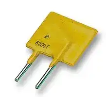


MF-R250-0-10
Resettable Fuse, PPTC, MF-R, 30 VDC, 2.5 A, 5 A, 10.3 s, Rectangular
- Manufacturer: BOURNS
- Product type: Radial Leaded PPTCs
- Thermistor Mounting:Through Hole; Product Range:MF-R Series; Holding Current:2.5A; Tripping Current:5A; Voltage Rating:30V; Operating Temperature Min:-40°C; Operating Temperature
- SVHC: No SVHC (04-Feb-2026)
- Height: 18.3mm
- Length: 12mm
- Diameter: -
- Thickness: 3mm
- Fuse Shape: Rectangular
- Lead Spacing: 5.1mm
- Time to Trip: 10.3s
- Trip Current: 5A
- Product Range: MF-R
- Voltage Rating: 30VDC
- Holding Current: 2.5A
- Current Rating Max: 40A
- Thermistor Mounting: Through Hole
- Operating Temperature Max: 85°C
- Operating Temperature Min: -40°C
- Automotive Qualification Standard: -
| Delivery and price | |
|---|---|
| Units per pack | 3000 |
| Price | 0.261 € |
| Current stock | 1000+ |
| Lead time | 30 days |
**==> picture [53 x 51] intentionally omitted <==**

**----- Start of picture text -----**<br>
&<br>*RoHS COMPLIANT<br>**HALOGEN FREE<br>**----- End of picture text -----**<br>


## **Features**

n Radial Leaded Devices

n Cured, flame retardant epoxy polymer insulating material meets UL 94V-0 requirements

- n RoHS compliant* and halogen free** n Agency recognition: cWANis &

## **Applications**

Almost anywhere there is a low voltage power supply and a load to be protected, including: n Computers & peripherals n General electronics

n Automotive applications

## **MF-R Series - PTC Resettable Fuses**

## ~~**Electrical Characteristics**~~

|**Model**|**V max.**<br>**Volts**|**I max.**<br>**Amps**|**Ihold**|**Itrip**|**Initial**<br>**Resistance**|**Initial**<br>**Resistance**|**1 Hour (R1)**<br>**Post-Trip**<br>**Resistance**|**Max. Time**<br>**to Trip**|**Max. Time**<br>**to Trip**|**Tripped**<br>**Power**<br>**Dissipation**|
|---|---|---|---|---|---|---|---|---|---|---|
||||**Amperes**<br>**at 23°C**||**Ohms**<br>**at 23°C**||**Ohms**<br>**at 23°C**|**Amperes**<br>**at 23°C**|**Seconds**<br>**at 23°C**|**Dissipation**<br>**Watts**<br>**at 23°C**|
||||Hold|Trip|Min.|Max.|Max.|||Typ.|
|MF-R005<br>~~a~~|60<br>~~a~~|40<br>~~a~~|0.05<br>~~GC~~|Trip<br>0.10<br>~~GC~~|7.3<br>~~GC~~|11.1<br>~~GC~~|22.0<br>~~GC~~|0.5<br>~~GC~~|5.0<br>~~GC~~|Typ.<br>0.22<br>~~GC~~|
|MF-R010<br>~~a~~<br>~~Po~~|60<br>~~a~~<br>~~Po~~|40<br>~~a ~~<br>~~Po~~|0.10<br> ~~GC~~<br>~~Po~~|0.20<br>~~GC~~<br>~~Po~~|2.50<br>~~GC~~<br>~~Po~~|4.50<br>~~GC~~<br>~~Po~~|7.50<br>~~GC~~<br>~~Po~~|0.5<br>~~GC~~<br>~~Po~~|4.0<br>~~GC~~<br>~~Po~~|0.38<br>~~GC~~<br>~~Po~~|
|MF-R017<br>~~a~~|60<br>~~a~~|40<br>~~a~~|0.17<br>~~GC~~|0.34<br>~~GC~~|2.00<br>~~GC~~|3.20<br>~~GC~~|8.00<br>~~GC~~|0.85<br>~~GC~~|3.0<br>~~GC~~|0.48<br>~~GC~~|
|MF-R020<br>~~a~~<br>~~Po~~|60<br>~~a~~<br>~~Po~~|40<br>~~a ~~<br>~~Po~~|0.20<br> ~~GC~~<br>~~Po~~|0.40<br>~~GC~~<br>~~Po~~|1.50<br>~~GC~~<br>~~Po~~|2.84<br>~~GC~~<br>~~Po~~|4.40<br>~~GC~~<br>~~Po~~|1.0<br>~~GC~~<br>~~Po~~|2.2<br>~~GC~~<br>~~Po~~|0.40<br>~~GC~~<br>~~Po~~|
|MF-R025<br>~~a~~|60<br>~~a~~|40<br>~~a~~|0.25<br>~~GC~~|0.50<br>~~GC~~|1.00<br>~~GC~~|1.95<br>~~GC~~|3.00<br>~~GC~~|1.25<br>~~GC~~|2.5<br>~~GC~~|0.45<br>~~GC~~|
|MF-R030<br>~~a~~<br>~~Po~~|60<br>~~a~~<br>~~Po~~|40<br>~~a ~~<br>~~Po~~|0.30<br> ~~GC~~<br>~~Po~~|0.60<br>~~GC~~<br>~~Po~~|0.76<br>~~GC~~<br>~~Po~~|1.36<br>~~GC~~<br>~~Po~~|2.10<br>~~GC~~<br>~~Po~~|1.5<br>~~GC~~<br>~~Po~~|3.0<br>~~GC~~<br>~~Po~~|0.50<br>~~GC~~<br>~~Po~~|
|MF-R040<br>~~a~~|60<br>~~a~~|40<br>~~a~~|0.40<br>~~GC~~|0.80<br>~~GC~~|0.52<br>~~GC~~|0.86<br>~~GC~~|1.29<br>~~GC~~|2.0<br>~~GC~~|3.8<br>~~GC~~|0.55<br>~~GC~~|
|MF-R050<br>~~a~~<br>~~Po~~|60<br>~~a~~<br>~~Po~~|40<br>~~a ~~<br>~~Po~~|0.50<br> ~~GC~~<br>~~Po~~|1.00<br>~~GC~~<br>~~Po~~|0.41<br>~~GC~~<br>~~Po~~|0.77<br>~~GC~~<br>~~Po~~|1.17<br>~~GC~~<br>~~Po~~|2.5<br>~~GC~~<br>~~Po~~|4.0<br>~~GC~~<br>~~Po~~|0.75<br>~~GC~~<br>~~Po~~|
|MF-R065<br>~~a~~|60<br>~~a~~|40<br>~~a~~|0.65<br>~~GC~~|1.30<br>~~GC~~|0.27<br>~~GC~~|0.48<br>~~GC~~|0.72<br>~~GC~~|3.25<br>~~GC~~|5.3<br>~~GC~~|0.90<br>~~GC~~|
|MF-R075<br>~~a~~<br>~~Po~~|60<br>~~a~~<br>~~Po~~|40<br>~~a ~~<br>~~Po~~|0.75<br> ~~GC~~<br>~~Po~~|1.50<br>~~GC~~<br>~~Po~~|0.18<br>~~GC~~<br>~~Po~~|0.40<br>~~GC~~<br>~~Po~~|0.60<br>~~GC~~<br>~~Po~~|3.75<br>~~GC~~<br>~~Po~~|6.3<br>~~GC~~<br>~~Po~~|0.90<br>~~GC~~<br>~~Po~~|
|MF-R090<br>~~a~~|60<br>~~a~~|40<br>~~a~~|0.90<br>~~GC~~|1.80<br>~~GC~~|0.14<br>~~GC~~|0.31<br>~~GC~~|0.47<br>~~GC~~|4.5<br>~~GC~~|7.2<br>~~GC~~|1.00<br>~~GC~~|
|MF-R090-0-9<br>~~a~~<br>~~Po~~|30<br>~~a~~<br>~~Po~~|40<br>~~a ~~<br>~~Po~~|0.90<br> ~~GC~~<br>~~Po~~|1.80<br>~~GC~~<br>~~Po~~|0.07<br>~~GC~~<br>~~Po~~|0.12<br>~~GC~~<br>~~Po~~|0.22<br>~~GC~~<br>~~Po~~|4.5<br>~~GC~~<br>~~Po~~|5.9<br>~~GC~~<br>~~Po~~|0.60<br>~~GC~~<br>~~Po~~|
|MF-R110<br>~~a~~|30<br>~~a~~|40<br>~~a~~|1.10<br>~~GC~~|2.20<br>~~GC~~|0.10<br>~~GC~~|0.18<br>~~GC~~|0.27<br>~~GC~~|5.5<br>~~GC~~|6.6<br>~~GC~~|0.70<br>~~GC~~|
|MF-R135<br>~~a~~<br>~~Po~~|30<br>~~a~~<br>~~Po~~|40<br>~~a ~~<br>~~Po~~|1.35<br> ~~GC~~<br>~~Po~~|2.70<br>~~GC~~<br>~~Po~~|0.065<br>~~GC~~<br>~~Po~~|0.115<br>~~GC~~<br>~~Po~~|0.17<br>~~GC~~<br>~~Po~~|6.75<br>~~GC~~<br>~~Po~~|7.3<br>~~GC~~<br>~~Po~~|0.80<br>~~GC~~<br>~~Po~~|
|MF-R160<br>~~a~~|30<br>~~a~~|40<br>~~a~~|1.60<br>~~GC~~|3.20<br>~~GC~~|0.055<br>~~GC~~|0.105<br>~~GC~~|0.15<br>~~GC~~|8.0<br>~~GC~~|8.0<br>~~GC~~|0.90<br>~~GC~~|
|MF-R185<br>~~a~~<br>~~Po~~|30<br>~~a~~<br>~~Po~~|40<br>~~a ~~<br>~~Po~~|1.85<br> ~~GC~~<br>~~Po~~|3.70<br>~~GC~~<br>~~Po~~|0.040<br>~~GC~~<br>~~Po~~|0.07<br>~~GC~~<br>~~Po~~|0.11<br>~~GC~~<br>~~Po~~|9.25<br>~~GC~~<br>~~Po~~|8.7<br>~~GC~~<br>~~Po~~|1.00<br>~~GC~~<br>~~Po~~|
|MF-R250<br>~~a~~|30<br>~~a~~|40<br>~~a~~|2.50<br>~~GC~~|5.00<br>~~GC~~|0.025<br>~~GC~~|0.048<br>~~GC~~|0.07<br>~~GC~~|12.5<br>~~GC~~|10.3<br>~~GC~~|1.20<br>~~GC~~|
|MF-R250-0-10<br>~~a~~<br>~~Po~~|30<br>~~a~~<br>~~Po~~|40<br>~~a ~~<br>~~Po~~|2.50<br> ~~GC~~<br>~~Po~~|5.00<br>~~GC~~<br>~~Po~~|0.025<br>~~GC~~<br>~~Po~~|0.048<br>~~GC~~<br>~~Po~~|0.07<br>~~GC~~<br>~~Po~~|12.5<br>~~GC~~<br>~~Po~~|10.3<br>~~GC~~<br>~~Po~~|1.20<br>~~GC~~<br>~~Po~~|
|MF-R300<br>~~a~~|30<br>~~a~~|40<br>~~a~~|3.00<br>~~GC~~|6.00<br>~~GC~~|0.020<br>~~GC~~|0.05<br>~~GC~~|0.08<br>~~GC~~|15.0<br>~~GC~~|10.8<br>~~GC~~|2.00<br>~~GC~~|
|MF-R400<br>~~a~~<br>~~Po~~|30<br>~~a~~<br>~~Po~~|40<br>~~a ~~<br>~~Po~~|4.00<br> ~~GC~~<br>~~Po~~|8.00<br>~~GC~~<br>~~Po~~|0.010<br>~~GC~~<br>~~Po~~|0.03<br>~~GC~~<br>~~Po~~|0.05<br>~~GC~~<br>~~Po~~|20.0<br>~~GC~~<br>~~Po~~|12.7<br>~~GC~~<br>~~Po~~|2.50<br>~~GC~~<br>~~Po~~|
|MF-R500<br>~~a~~|30<br>~~a~~|40<br>~~a~~|5.00<br>~~GC~~|10.00<br>~~GC~~|0.010<br>~~GC~~|0.03<br>~~GC~~|0.05<br>~~GC~~|25.0<br>~~GC~~|14.5<br>~~GC~~|3.00<br>~~GC~~|
|MF-R600<br>~~a~~<br>~~Po~~|30<br>~~a~~<br>~~Po~~|40<br>~~a ~~<br>~~Po~~|6.00<br> ~~GC~~<br>~~Po~~|12.00<br>~~GC~~<br>~~Po~~|0.005<br>~~GC~~<br>~~Po~~|0.02<br>~~GC~~<br>~~Po~~|0.04<br>~~GC~~<br>~~Po~~|30.0<br>~~GC~~<br>~~Po~~|16.0<br>~~GC~~<br>~~Po~~|3.50<br>~~GC~~<br>~~Po~~|
|MF-R700<br>~~a~~|30<br>~~a~~|40<br>~~a~~|7.00<br>~~GC~~|14.00<br>~~GC~~|0.005<br>~~GC~~|0.02<br>~~GC~~|0.03<br>~~GC~~|35.0<br>~~GC~~|17.5<br>~~GC~~|3.80<br>~~GC~~|
|MF-R800<br>~~a~~<br>~~Po~~|30<br>~~a~~<br>~~Po~~|40<br>~~a ~~<br>~~Po~~|8.00<br> ~~GC~~<br>~~Po~~|16.00<br>~~GC~~<br>~~Po~~|0.005<br>~~GC~~<br>~~Po~~|0.02<br>~~GC~~<br>~~Po~~|0.03<br>~~GC~~<br>~~Po~~|40.0<br>~~GC~~<br>~~Po~~|18.8<br>~~GC~~<br>~~Po~~|4.00<br>~~GC~~<br>~~Po~~|
|MF-R900<br>~~a~~|30<br>~~a~~|40<br>~~a~~|9.00<br>~~GC~~|18.00<br>~~GC~~|0.005<br>~~GC~~|0.01<br>~~GC~~|0.02<br>~~GC~~|40.0<br>~~GC~~|20.0<br>~~GC~~|4.20<br>~~GC~~|
|MF-R1100<br>~~a~~<br>~~Po~~|16<br>~~a~~<br>~~Po~~|100<br>~~a ~~<br>~~Po~~|11.00<br> ~~GC~~<br>~~Po~~|22.00<br>~~GC~~<br>~~Po~~|0.003<br>~~GC~~<br>~~Po~~|0.01<br>~~GC~~<br>~~Po~~|0.014<br>~~GC~~<br>~~Po~~|40.0<br>~~GC~~<br>~~Po~~|20.0<br>~~GC~~<br>~~Po~~|4.50<br>~~GC~~<br>~~Po~~|


## ~~**Environmental Characteristics**~~

|~~**Environmental Characteristics**~~||
|---|---|
|Operating/Storage Temperature ...................... -40 °C to +85 °C|Operating/Storage Temperature ...................... -40 °C to +85 °C|
|Maximum Device Surface Temperature||
|in Tripped State ............................................ 125 °C|in Tripped State ............................................ 125 °C|
|Passive Aging .................................................. +85 °C, 1000 hours ...........................................±5 % typical resistance change|Passive Aging .................................................. +85 °C, 1000 hours ...........................................±5 % typical resistance change|
|Humidity Aging................................................. +85 °C, 85 % R.H. 1000 hours .........................±5 % typical resistance change|Humidity Aging................................................. +85 °C, 85 % R.H. 1000 hours .........................±5 % typical resistance change|
|Thermal Shock ................................................ -40 °C to +85 °C, 10 times ................................±10 % typical resistance change|Thermal Shock ................................................ -40 °C to +85 °C, 10 times ................................±10 % typical resistance change|
|Solvent Resistance .......................................... MIL-STD-202, Method 215 ...............................No change|Solvent Resistance .......................................... MIL-STD-202, Method 215 ...............................No change|
|Vibration .......................................................... MIL-STD-883C, Method 2007.1,.......................No change|Vibration .......................................................... MIL-STD-883C, Method 2007.1,.......................No change|
||Condition A|


## ~~**Test Procedures And Requirements For Model MF-R Series**~~

|**Test**<br>**Test Conditions**<br>**Accept/Reject Criteria**|
|---|
|Visual/Mech. .................................................... Verify dimensions and materials .......................Per MF physical description|
|Resistance ....................................................... In still air @ 23 °C .............................................Rmin≤R≤Rmax|
|Time to Trip ...................................................... 5 times Ihold, Vmax, 23 °C ...............................T≤max. time to trip (seconds)|
|Hold Current .................................................... 30 min. at Ihold .................................................No trip|
|Trip Cycle Life .................................................. Vmax, Imax, 100 cycles ....................................No arcing or burning|
|Trip Endurance ................................................ Vmax, 48 hours .................................................No arcing or burning|
|UL File Number ............................................... E174545|
|TÜV File Number ............................................. R2057213|


- RoHS Directive 2002/95/EC Jan. 27, 2003 including annex and RoHS Recast 2011/65/EU June 8, 2011.

** Bourns follows the prevailing definition of “halogen free” in the industry.  Bourns considers a product to be “halogen free” if (a) the Bromine (Br) content is 900 ppm or less; (b) the Chlorine (Cl) content is 900 ppm or less; and (c) the total Bromine (Br) and Chlorine (Cl) content is 1500 ppm or less. Specifications are subject to change without notice.

The device characteristics and parameters in this data sheet can and do vary in different applications and actual device performance may vary over time. Users should verify actual device performance in their specific applications.

n Bulk packaging, tape and reel and Ammo-Pak available on most models

## **Additional Features**

## **MF-R Series - PTC Resettable Fuses**

**==> picture [518 x 612] intentionally omitted <==**

**----- Start of picture text -----**<br>
Product Dimensions (see next page for outline drawing)<br>   Model  A  B                       C  D  E   Physical Characteristics<br>Max.  Max.  Nom.  Tol. ±  Min.  Max.  Style  Lead Dia.  Material<br>8.0  8.3  5.1  0.7  7.6  3.1  0.405<br> MF-R005  4 Sn/NiCu<br>(0.315) (0.327) (0.201) (0.028) (0.299) (0.122) (0.016)<br>7.4  12.7  5.1  0.7  7.6 3.1  0.51<br> MF-R010  1 Sn/NiCu<br>(0.291) (0.5) (0.201) (0.028) (0.299) (0.122) (0.020)<br>7.4  12.7  5.1  0.7  7.6  3.1  0.51<br> MF-R017  1 Sn/CuFe<br>(0.291) (0.5) (0.201) (0.028) (0.299) (0.122) (0.020)<br>7.4  12.7  5.1  0.7  7.6 3.1  0.51<br> MF-R020  1 Sn/CuFe<br>(0.291) (0.5) (0.201) (0.028) (0.299) (0.122) (0.020)<br>7.4  12.7  5.1  0.7  7.6  3.1  0.51<br> MF-R025  1 Sn/CuFe<br>(0.291) (0.5) (0.201) (0.028) (0.299) (0.122) (0.020)<br>7.4  13.4  5.1  0.7  7.6  3.1  0.51<br> MF-R030  1 Sn/CuFe<br>(0.291) (0.528) (0.201) (0.028) (0.299) (0.122) (0.020)<br>7.4  13.7  5.1  0.7  7.6  3.1  0.51<br> MF-R040  1 Sn/CuFe<br>(0.291) (0.539) (0.201) (0.028) (0.299) (0.122) (0.020)<br>7.9  13.7  5.1  0.7  7.6  3.1  0.51<br> MF-R050  1 Sn/Cu<br>(0.311) (0.539) (0.201) (0.028) (0.299) (0.122) (0.020)<br>9.7  15.2  5.1  0.7  7.6  3.1  0.51<br> MF-R065  1 Sn/Cu<br>(0.382) (0.598) (0.201) (0.028) (0.299) (0.122) (0.020)<br>10.4  16.0  5.1  0.7  7.6  3.1  0.51<br> MF-R075  1 Sn/Cu<br>(0.409) (0.630) (0.201) (0.028) (0.299) (0.122) (0.020)<br>11.7  16.7  5.1  0.7  7.6  3.1  0.51<br> MF-R090  1 Sn/Cu<br>(0.461) (0.657) (0.201) (0.028) (0.299) (0.122) (0.020)<br>7.4  12.2  5.1  0.7  7.6 3.0 0.51<br> MF-R090-0-9  3 Sn/CuFe<br>(0.291) (0.480) (0.201) (0.028) (0.299) (0.118) (0.020)<br>8.9 14.0 5.1  0.7  7.6 3.0 0.51<br> MF-R110  1 Sn/Cu<br>(0.350) (0.551) (0.201) (0.028) (0.299) (0.118) (0.020)<br>8.9 18.9 5.1  0.7  7.6 3.0 0.51<br> MF-R135  1 Sn/Cu<br>(0.350) (0.744) (0.201) (0.028) (0.299) (0.118) (0.020)<br>10.2  16.8  5.1  0.7  7.6  3.0  0.51<br> MF-R160  1 Sn/Cu<br>(0.402) (0.661) (0.201) (0.028) (0.299) (0.118) (0.020)<br>12.0  18.4  5.1  0.7  7.6  3.0  0.51<br> MF-R185  1 Sn/Cu<br>(0.472) (0.724) (0.201) (0.028) (0.299) (0.118) (0.020)<br>12.0 18.3 5.1  0.7  7.6 3.0 0.81<br> MF-R250  2 Sn/Cu<br>(0.472) (0.720) (0.201) (0.028) (0.299) (0.118) (0.032)<br>12.0  18.3  5.1  0.7  7.6  3.0  0.51<br> MF-R250-0-10  3 Sn/CuFe<br>(0.472) (0.720) (0.201) (0.028) (0.299) (0.118) (0.020)<br>12.0  18.3  5.1  0.7  7.6  3.0  0.81<br> MF-R300  2 Sn/Cu<br>(0.472) (0.720) (0.201) (0.028) (0.299) (0.118) (0.032)<br>14.4  24.8  5.1  0.7  7.6  3.0  0.81<br> MF-R400  2 Sn/Cu<br>(0.567) (0.976) (0.201) (0.028) (0.299) (0.118) (0.032)<br>17.4  24.9  10.2  0.7  7.6  3.0  0.81<br> MF-R500  2 Sn/Cu<br>(0.685) (0.980) (0.402) (0.028) (0.299) (0.118) (0.032)<br>19.3 31.9 10.2  0.7  7.6 3.0 0.81<br> MF-R600  2 Sn/Cu<br>(0.760) (1.256) (0.402) (0.028) (0.299) (0.118) (0.032)<br>22.1  29.8 10.2  0.7  7.6 3.0 0.81<br> MF-R700  2 Sn/Cu<br>(0.870) (1.173) (0.402) (0.028) (0.299) (0.118) (0.032)<br>24.2  32.9  10.2  0.7  7.6  3.0  0.81<br> MF-R800  2 Sn/Cu<br>(0.953) (1.295) (0.402) (0.028) (0.299) (0.118) (0.032)<br>24.2  32.9  10.2  0.7  7.6  3.0  0.81<br> MF-R900  2 Sn/Cu<br>(0.953) (1.295) (0.402) (0.028) (0.299) (0.118) (0.032)<br>24.2  32.9  10.2  0.7  7.6  3.0  0.81<br> MF-R1100  2 Sn/Cu<br>(0.953)  (1.295)  (0.402)  (0.028)  (0.299)  (0.118)  (0.032)<br>Packaging options:   0.405 (26AWG)  MM<br>BULK:   All models = 500 pcs. per bag 0.51 (24AWG) 0.81 (20AWG) DIMENSIONS: (INCHES)<br>TAPE & REEL:  MF-R005-MF-R160    12.7 mm device pitch = 3000 pcs. per reel<br>MF-R185-MF-R400    25.4 mm device pitch = 1500 pcs. per reel<br>MF-R500~MF-R1100  25.4 mm device pitch = 1000 pcs. per reel<br>AMMO-PACK:  MF-R005-MF-R160    12.7 mm device pitch = 2000 pcs. per pack<br>MF-R185-MF-R400    25.4 mm device pitch = 1000 pcs. per pack<br>MF-R500~MF-R1100 25.4 mm device pitch =   500 pcs. per pack<br>**----- End of picture text -----**<br>


Specifications are subject to change without notice. The device characteristics and parameters in this data sheet can and do vary in different applications and actual device performance may vary over time. Users should verify actual device performance in their specific applications.

## **MF-R Series - PTC Resettable Fuses**

## ~~**Product Dimensions (see previous page for dimensions)**~~

**==> picture [481 x 204] intentionally omitted <==**

**----- Start of picture text -----**<br>
Style 1 Style 2 Style 3 Style 4<br>A E A E A E A E<br>B<br>B B B<br>D<br>C<br>D<br>D D<br>C C C<br>NOTE: Kinked lead option is   NOTE: Also available with<br>available for board standoff.   straight leads. Contact<br>Contact factory for details. factory for details.<br>**----- End of picture text -----**<br>


## ~~**Thermal Derating Chart - Ihold / Itrip (Amps)**~~

|**Model**|**Ambient Operating Temperature**|**Ambient Operating Temperature**|**Ambient Operating Temperature**|**Ambient Operating Temperature**|**Ambient Operating Temperature**|**Ambient Operating Temperature**|**Ambient Operating Temperature**|**Ambient Operating Temperature**|**Ambient Operating Temperature**|
|---|---|---|---|---|---|---|---|---|---|
||**-40 ºC**|**-20 ºC**|**0 ºC**|**23 ºC**|**40 ºC**|**50 ºC**|**60 ºC**|**70 ºC**|**85 ºC**|
|MF-R005|0.08/0.16|0.07 /0.14|0.06/0.12|0.05/0.10|0.04 /0.08|0.04 /0.08|0.03/0.07|0.03/0.07|0.02 /0.05|
|MF-R010|0.16/0.32|0.14 /0.28|0.12 /0.24|0.10/0.20|0.08/0.16|0.07 /0.14|0.06/0.12|0.05/0.10|0.04 /0.08|
|MF-R017|0.26/0.52|0.23/0.46|0.20/0.40|0.17 /0.34|0.14 /0.28|0.12 /0.24|0.11 /0.22|0.09/0.18|0.07 /0.14|
|MF-R020|0.31 /0.62|0.27 /0.54|0.24 /0.48|0.20/0.40|0.16/0.32|0.14 /0.28|0.13/0.26|0.11 /0.22|0.08/0.16|
|MF-R025|0.39/0.78|0.34 /0.68|0.30/0.60|0.25/0.50|0.20/0.40|0.18/0.36|0.16/0.32|0.14 /0.28|0.10/0.20|
|MF-R030|0.47 /0.94|0.41 /0.82|0.36/0.72|0.30/0.60|0.24 /0.48|0.22 /0.44|0.19/0.38|0.16/0.32|0.12 /0.24|
|MF-R040|0.62 / 1.24|0.54 / 1.08|0.48/0.96|0.40/0.80|0.32 /0.64|0.29/0.58|0.25/0.50|0.22 /0.44|0.16/0.32|
|MF-R050|0.78/ 1.56|0.68/ 1.36|0.60/ 1.20|0.50/ 1.00|0.41 /0.82|0.36/0.72|0.32 /0.64|0.27 /0.54|0.20/0.40|
|MF-R065|1.01 / 2.02|0.88/ 1.76|0.77 / 1.54|0.65/ 1.30|0.53/ 1.06|0.47 /0.94|0.41 /0.82|0.35/0.70|0.26/0.52|
|MF-R075|1.16/ 2.32|1.02 / 2.04|0.89/ 1.78|0.75/ 1.50|0.61 / 1.22|0.54 / 1.08|0.47 /0.94|0.41 /0.82|0.30/0.60|
|MF-R090|1.40/ 2.80|1.22 / 2.44|1.07 / 2.14|0.90/ 1.80|0.73/ 1.46|0.65/ 1.30|0.57 / 1.14|0.49/0.98|0.36/0.72|
|MF-R090-0-9|1.40/ 2.80|1.22 / 2.44|1.07 / 2.14|0.90/ 1.80|0.73/ 1.46|0.65/ 1.30|0.57 / 1.14|0.49/0.98|0.36/0.72|
|MF-R110|1.60/3.20|1.43/ 2.86|1.27 / 2.54|1.10/ 2.20|0.91 / 1.82|0.85/ 1.70|0.75/ 1.50|0.67 / 1.34|0.57 / 1.14|
|MF-R135|1.96/3.92|1.76/3.52|1.55/3.10|1.35/ 2.70|1.12 / 2.24|1.04 / 2.08|0.92 / 1.84|0.82 / 1.64|0.70/ 1.40|
|MF-R160|2.32 / 4.64|2.08/ 4.16|1.84 /3.68|1.60/3.20|1.33/ 2.66|1.23/ 2.46|1.09/ 2.18|0.98/ 1.96|0.83/ 1.66|
|MF-R185|2.68/5.36|2.41 / 4.82|2.13/ 4.26|1.85/3.70|1.54 /3.08|1.42 / 2.84|1.26/ 2.52|1.13/ 2.26|0.96/ 1.92|
|MF-R250|3.63/ 7.26|3.25/6.50|2.88/5.76|2.50/5.00|2.08/ 4.16|1.93/3.86|1.70/3.40|1.53/3.06|1.30/ 2.60|
|MF-R250-0-10|3.63/ 7.26|3.25/6.50|2.88/5.76|2.50/5.00|2.08/ 4.16|1.93/3.86|1.70/3.40|1.53/3.06|1.30/ 2.60|
|MF-R300|4.35/8.70|3.90/ 7.80|3.45/6.90|3.00/6.00|2.49/ 4.98|2.31 / 4.62|2.04 / 4.08|1.83/3.66|1.56/3.12|
|MF-R400|5.80/ 11.6|5.20/ 10.4|4.60/9.20|4.00/8.00|3.32 /6.64|3.08/6.16|2.72 /5.44|2.44 / 4.88|2.08/ 4.16|
|MF-R500|7.25/ 14.5|6.50/ 13.0|5.75/ 11.5|5.00/ 10.0|4.15/8.30|3.85/ 7.70|3.40/6.80|3.05/6.10|2.60/5.20|
|MF-R600|8.70/ 17.4|7.80/ 15.6|6.90/ 13.8|6.00/ 12.0|4.98/9.96|4.62 /9.24|4.08/8.16|3.66/ 7.32|3.12 /6.24|
|MF-R700|10.1 / 20.3|9.10/ 18.2|8.05/ 16.1|7.00/ 14.0|5.81 / 11.6|5.39/ 10.7|4.76/9.52|4.27 /9.44|3.64 / 7.28|
|MF-R800|11.6/ 23.2|10.4 / 20.8|9.20/ 18.4|8.00/ 16.0|6.64 / 13.2|6.16/ 12.3|5.44 / 10.8|4.88/9.76|4.16/8.32|
|MF-R900|13.0/ 26.1|11.7 / 23.4|10.3/ 20.7|9.00/ 18.0|7.47 / 14.9|6.93/ 12.7|6.12 / 12.2|5.49/ 10.9|4.68/9.36|
|MF-R1100|16.1 /32.0|14.6/ 29.2|13.1 / 26.2|11.0/ 22.1|9.40/ 18.4|8.80/ 17.6|7.80/ 15.6|6.90/ 13.8|5.20/ 10.4|


Specifications are subject to change without notice. The device characteristics and parameters in this data sheet can and do vary in different applications and actual device performance may vary over time. Users should verify actual device performance in their specific applications.

## **MF-R Series - PTC Resettable Fuses**

## ~~**Typical Time to Trip at 23 ºC**~~

~~**How to Order**~~ **MF - R  110 - 0 - 99** Multifuse[®] Product Designator

**==> picture [258 x 545] intentionally omitted <==**

**----- Start of picture text -----**<br>
100<br>10<br>1<br>0.1<br>0.01<br>0.001<br>0.1 1 10 100<br>Fault Current (Amps)<br>100<br>10<br>1<br>0.1<br>0.01<br>0.001<br>1 10 100<br>Fault Current (Amps)<br>MF-R005MF-R010MF-R017MF-R020MF-R025MF-R030MF-R040MF-R050MF-R065MF-R075MF-R090<br>MF-R090MF-R110MF-R135MF-R160MF-R185MF-R250,250-0-10MF-R300MF-R400MF-R500MF-R600MF-R700MF-R800MF-R900MF-R1100<br>  -0-9<br>Time to trip (Seconds)<br>Time to trip (Seconds)<br>**----- End of picture text -----**<br>


Series

- R = Radial Leaded Component Hold Current, Ihold 005-1100 (0.05 Amps - 11.0 Amps) Packaging Options - __ = Bulk Packaging without part number suffix option

- - 0-99 = Bulk Packaging with part number suffix option

- - 2 = Tape and Reel without part number suffix option*

- - 2-99 = Tape and Reel with part number suffix option

- - AP = Ammo-Pak*

- 0-14 = Kinked leads where straight leads are standard

- - 0-17 = Straight leads where kinked leads are standard

- Part Number Suffix Option - 99 = As of date code April 1, 2005 all MF-R models are RoHS compliant. The suffix “-99” can be used if a new part number is required to reference the RoHS compliance. Examples: MF-R110 ..................Bulk packaging MF-R110-0-99 .........Bulk packaging with part number suffix option

- MF-R110-2...............Tape and reel packaging

- MF-R110-2-99 .........Tape and reel packaging with part number suffix option

- MF-R090-0-9-99 ......Bulk packaging with part number suffix option

- MF-R250-0-10-99 ....Bulk packaging with part number suffix option

*Packaged per EIA486-B

**==> picture [167 x 74] intentionally omitted <==**

**----- Start of picture text -----**<br>
Typical Part Marking: MF-R005 - R025<br>Represents total content. Layout may vary.<br>PART  DATE CODE:<br>IDENTIFICATION 025 WEEK 1 OF 2000 = 0A<br>MANUFACTURER'S 0A (YEAR & WEEK)WEEK 27 OF 2000 = A0<br>TRADEMARK (WEEK & YEAR)<br>**----- End of picture text -----**<br>


**==> picture [167 x 99] intentionally omitted <==**

**----- Start of picture text -----**<br>
Typical Part Marking: MF-R030 - R1100<br>Represents total content. Layout may vary.<br>MANUFACTURER'S<br>TRADEMARK<br>PART<br>IDENTIFICATION<br>R250 LOT NO.<br>DATE CODE 0180T (T = TAIWAN<br>(FIRST DIGIT =  S = CHINA)<br>LAST DIGIT OF YEAR;<br>NEXT THREE DIGITS =<br>DAY OF YEAR)<br>**----- End of picture text -----**<br>


MF-R SERIES, REV. AF, 07/17 Specifications are subject to change without notice. The device characteristics and parameters in this data sheet can and do vary in different applications and actual device performance may vary over time. Users should verify actual device performance in their specific applications.

## **MF-R, MF-R/90, MF-R/600, & MF-RX, & MF-RX/72 Series Tape and Reel Specifications**

Devices taped using EIA468–B/IEC286-2 standards.  See table below and Figures 1 and 2 for details.

|Devices taped using EIA468–B/IEC286-2 standards.  See table below and Figures 1 and 2 for details.|Devices taped using EIA468–B/IEC286-2 standards.  See table below and Figures 1 and 2 for details.|Devices taped using EIA468–B/IEC286-2 standards.  See table below and Figures 1 and 2 for details.|Devices taped using EIA468–B/IEC286-2 standards.  See table below and Figures 1 and 2 for details.|Devices taped using EIA468–B/IEC286-2 standards.  See table below and Figures 1 and 2 for details.|
|---|---|---|---|---|
|**IEC**<br>**EIA**<br>**Dimensions**<br>**Dimension Description**<br>**Mark**<br>**Mark**<br>**Dimensions**<br>**Tolerance**|||||
|Carrier tape width<br>_W_<br>_W_|18<br>(.709)|-0.5/+1.0<br>(-0.02/+.039)|||
|Hold down tape width<br>_W4_<br>_W0_|11<br>(.433)|min.|||
|Hold down tape<br> <br>No|protrusion||||
|Top distance between tape edges<br>_W2_<br>_W6_|3<br>(.118)|max.|||
|Sprocket hole position<br>_W1_<br>_W5_|9<br>(.354)|-0.5/+0.75<br>(-0.02/+0.03)|||
|Sprocket hole diameter<br>_D0_<br>_D0_|4<br>(.157)||±0.2<br>(±.0078)||
|Abscissa to plane (straight lead)<br>_H_<br>_H_|18.5<br>(.728)||±3.0<br>(±.118)||
|Abscissa to plane (kinked lead)<br>_H0_<br>_H0_|16<br>(.63)||±0.5<br>(±.02)||
|Abscissa to top (straight lead)<br>_H1_<br>_H1_|38.0<br>(1.496)||max.||
|Abscissa to top (kinked lead)<br>_H1_<br>_H1_|32.2<br>(1.268)||max.||
|Overall width w/lead protrusion (straight lead)<br>_C1_|55.0<br>(2.165)||max.||
|Overall width w/lead protrusion (kinked lead)<br>_C1_|43.2<br>(1.7)||max.||
|Overall width w/o lead protrusion (straight lead)<br>_C2_|54.0<br>(2.126)||max.||
|Overall width w/o lead protrusion (kinked lead)<br>_C2_|42.5<br>(1.673)||max.||
|Lead protrusion<br>_I1_<br>_L1_|1.0<br>(.039)||max.||
|Protrusion of cutout<br>_L_<br>_L_|11<br>(.433)||max.||
|Protrusion beyond hold-down tape<br>_I2_<br>_I2_<br>Not specifed|||||
|Sprocket hole pitch<br>_P0_<br>_P0_|12.7<br>(0.5)||±0.3||
||||(±.012)||
|Pitch tolerance<br>20 consecutive|||±1||
||||(±.039)||
|Device pitch: MF-R005–MF-R160, MF-R/90,<br>MF-RX020/72–MF-RX030/72|12.7<br>(0.5)||±0.3<br>(±.012)||
|Device pitch: MF-R185–MF-R400, MF-R/600, MF-RX110–MF-RX375<br>MF-RX040/72–MF-RX375/72|25.4<br>(1.0)||±0.6||
||||(±.024)||
|Tape thickness<br>_t_<br>_t_|0.9<br>(.035)||max.||
|Tape thickness with splice: MF-R010–MF-R160,<br>_t1_<br>MF-RX110/72–MF-RX185/72|1.5<br>(.059)||max.||
|Tape thickness with splice: MF-R250–MF-R1100,<br>_t1_<br>MF-RX110–MF-RX375, MF-R/90, MF-RX250/72-MF-RX375/72|2.3<br>(.091)||max.||
|Splice sprocket hole alignment|0||±0.3||
||||(±.012)||
|Body lateral deviation<br>Δ_h_<br>Δ_h_|0||±1.0||
||||(±.039)||
|Body tape plane deviation<br>Δ_p_<br>Δ_p_|0||±1.3||
||||(±.051)||
||DIMENSIONS:|||MM|
|||||(INCHES)|


Specifications are subject to change without notice.

The device characteristics and parameters in this data sheet can and do vary in different applications and actual device performance may vary over time. Users should verify actual device performance in their specific applications.

## **MF-R, MF-R/90, MF-R/600, MF-RX, & MF-RX/72 Series Tape and Reel Specifications**

|**Dimension Description**|**Dimension Description**|**Dimension Description**|**Dimension Description**|**Dimension Description**|**Dimension Description**|**Dimension Description**|**Dimension Description**|**Dimension Description**||||**IEC**<br>**EIA**<br>**Dimensions**<br>**Mark**<br>**Mark**<br>**Dimensions**<br>**Tolerance**|**IEC**<br>**EIA**<br>**Dimensions**<br>**Mark**<br>**Mark**<br>**Dimensions**<br>**Tolerance**|**IEC**<br>**EIA**<br>**Dimensions**<br>**Mark**<br>**Mark**<br>**Dimensions**<br>**Tolerance**|**IEC**<br>**EIA**<br>**Dimensions**<br>**Mark**<br>**Mark**<br>**Dimensions**<br>**Tolerance**|**IEC**<br>**EIA**<br>**Dimensions**<br>**Mark**<br>**Mark**<br>**Dimensions**<br>**Tolerance**|**IEC**<br>**EIA**<br>**Dimensions**<br>**Mark**<br>**Mark**<br>**Dimensions**<br>**Tolerance**|**IEC**<br>**EIA**<br>**Dimensions**<br>**Mark**<br>**Mark**<br>**Dimensions**<br>**Tolerance**|**IEC**<br>**EIA**<br>**Dimensions**<br>**Mark**<br>**Mark**<br>**Dimensions**<br>**Tolerance**|**IEC**<br>**EIA**<br>**Dimensions**<br>**Mark**<br>**Mark**<br>**Dimensions**<br>**Tolerance**|**IEC**<br>**EIA**<br>**Dimensions**<br>**Mark**<br>**Mark**<br>**Dimensions**<br>**Tolerance**|**IEC**<br>**EIA**<br>**Dimensions**<br>**Mark**<br>**Mark**<br>**Dimensions**<br>**Tolerance**|
|---|---|---|---|---|---|---|---|---|---|---|---|---|---|---|---|---|---|---|---|---|---|---|
|Lead spacing: MF-R, MF-R/90, MF-R/600, MF-RX, MF-RX/72||||||||||||_F_<br>_F_|||||||5.08<br>(0.2)|||±0.2<br>(±0.008)|
|Reel width||||||||||||_w_<br>_W2_|||||||56.0<br>(2.205|)||max.|
|Reel diameter||||||||||||_d_<br>_a_|||||||370.0|)||max.|
||||||||||||||||||||(14.57||||
|Space between fanges less device||||||||||||_W1_<br>_h_|||||||4.75|||±3.25<br>(±.128)|
||||||||||||||||||||(.187)||||
|Arbor hole diameter||||||||||||_f_<br>_c_|||||||26.0<br>(1.024|)||±12.0<br>(±.472)|
|Core diameter: MF-R, MF-RX, MF-R/90||||||||||||_h_<br>_n_|||||||80<br>(3.15)|||max.|
|Core diameter: MF-R/600||||||||||||_h_<br>_n_|||||||91<br>(3.58)|||max.|
|Box: MF-R, MF-RX, MF-R/90||||||||||||||62<br>(2.44)|||||355<br>(14.0)|345<br>(13.6)||nom.|
|Box: MF-R/600||||||||||||||64<br>(2.52)|||||372<br>362<br>(14.6) (14.25)|||max.|
|Consecutive missing places: MF-||R, M|F~~-~~RX, MF-R/90||||||||||||||||3|||max.|
|Consecutive missing places: MF-||R/600|||||||||||||||||none||||
|Empty places per reel: MF-R, MF||-RX, MF-R/90|||||||||||||||Not speci|||fed|||
|Empty places per reel: MF-R/600|||||||||||||||||0.1 %||||||
||||||||||||||||||||||||
||||||||||||||||||||||||
||||||||||||||||||||||||


**Taped Component Dimensions - Figure 1**

**==> picture [401 x 300] intentionally omitted <==**

**----- Start of picture text -----**<br>
h h p p<br>Reference plane<br>H1  P1 F H1<br>H<br>L A B W0H0 W1W<br>I2 I1 P0 D0 User direction of feed<br>Cross section A - B<br>t<br>Reel<br>h Upper side<br>Tape<br>User<br>d direction<br>of<br>feed<br>Lower side<br>f<br>MM<br>wh DIMENSIONS: (INCHES)<br>**----- End of picture text -----**<br>


**Reel Dimensions - Figure 2**

Specifications are subject to change without notice. The device characteristics and parameters in this data sheet can and do vary in different applications and actual device performance may vary over time. Users should verify actual device performance in their specific applications.
Updated at April 27, 2026
Bourns, Inc. is a globally recognized manufacturer of high-reliability electronic components, headquartered in Riverside, California. Renowned for its engineering excellence, the company delivers critical solutions across a diverse range of demanding markets, including automotive, industrial, consumer electronics, telecommunications, and medical equipment. The Bourns product portfolio is anchored by an industry-leading selection of passive components and circuit protection devices. The brand is particularly dominant in magnetic components, offering thousands of high-performance power inductors, alongside specialized RF and toroidal inductors engineered for optimized power management and signal integrity. Equally prominent is their comprehensive suite of circuit protection solutions. This robust lineup features a vast array of standard and resettable fuses, transient voltage suppressors (including TVS varistors and diodes), and gas discharge tubes (GDTs) designed to rigorously safeguard sensitive electronics against overvoltage and overcurrent faults. Beyond its core passives and protection technologies, Bourns manufactures highly effective EMC and RFI suppression components, such as common mode chokes and power line filters. The company's offering also extends into discrete semiconductors and power management, including Schottky diodes, fast recovery rectifiers, bridge rectifiers, and board-level transformers. This expansive breadth of quality components provides design engineers with a trusted foundation for developing resilient, efficient, and long-lasting electronic systems.
About Novapart
Novapart is a B2B electronic component broker specialising in stock shortages and cost reduction. We source hard-to-find parts and identify compliant alternatives across a catalogue of 410,000+ components from 500+ manufacturers.
Learn more →Stock Shortage Specialist
When a component is unavailable, discontinued or has an unacceptable lead time, we tap into our network of vetted European and Asian distributors to source what you need — without compromising on quality or traceability.
Request a quote →Compliant Alternatives
We identify pin-to-pin, electrically equivalent substitutes that meet the same certifications (RoHS, AEC-Q100, REACH) as your original specification — validated against datasheets, not just part numbers. Often at a lower cost.
BOM Analysis service →