
Image not available
Illustrative purposes only

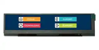
MDT0660AIH-LVDS
TFT LCD, 6.6
⚠️ Reference pricing provided. In case of supply shortages, we will connect you with our trusted procurement partners to ensure your project's continuity.
- Manufacturer: MIDAS
- Product type: TFT LCD Displays
- Resolution: 1440 x 240 Pixels
- Module Size: 178.4mm x 40mm
- Touchscreen: No Touchscreen
- Display Size: 6.6"
- Logic Voltage: 3.3V
- Display Pinout: 40 Way FFC
- Interface Type: LVDS
- Display Appearance: RGB
- Display Brightness: 1000cd/m²
- Display Orientation: Landscape
- Operating Temperature Max: 85°C
- Operating Temperature Min: -30°C
| Delivery and price | |
|---|---|
| Units per pack | 10 |
| Price | 114.51 € |
| Current stock | 10+ |
| Lead time | 7 days |
Datasheet

Electra House, 32 Southtown Road Great Yarmouth, Norfolk NR31 0DU, England

Telephone +44 (0)1493 602602 Email:sales@midasdisplays.com www.midasdisplays.com

**==> picture [409 x 70] intentionally omitted <==**

**----- Start of picture text -----**<br>
||||
|---|---|---|
|MDT0660AIH-LVDS|1440 x 240|LVDS Interface|
|Specification|
|Version:    1|Date:  01/06/2018|
|Revision|
|1|30/05/2018|First issue|

**----- End of picture text -----**<br>


TFT Module

**==> picture [524 x 187] intentionally omitted <==**

**----- Start of picture text -----**<br>
Display Features<br>a Display Size  6.60”<br>a Resolution  1440 x 240<br>ee Orientation  Landscape<br>Pe Appearance  Vee eee, Ve RGB<br>ee Logic Voltage  ) eee 1 eee 3.3V<br>Interface  LVDS<br>Brightness  1000 cd/m [2 ]<br>ee 1 eee 2 :<br>Touchscreen  ---<br>ee oY Ae 71 compliant<br>ee Module Size  ee Ae ee 178.40 x 40.00 x 3.35mm<br>a Operating Temperature  -30°C ~ +85°C<br>Pinout  40 way FFC Box Quantity Weight / Display<br>ee DO<br>PO Pitch UCI maniifactitraew 0.5mm e@ ---  ciubnhy, ---<br>**----- End of picture text -----**<br>


- - For full design functionality, please use this

**==> picture [498 x 101] intentionally omitted <==**

**----- Start of picture text -----**<br>
|||||
|---|---|---|---|
|Display Accessories|Optional Variants|
|Part Number|Description|Appearances|Voltage|
|40 Way FFC to cable and wires.|
|Driven by any driver board that can|
|MPBV6|
|be wired to a 1mm pitch|
|SHDR-40V-S-B receptacle.|
|HDMI-to-LVDS interface board,|
|MCIB14/16|
|with voltage generation.|

**----- End of picture text -----**<br>


## *** Description**

This is a color active matrix TFT (Thin Film Transistor) LCD (liquid crystal display) that uses amorphous silico n TFT as a switching device. This module is composed of a Transmissive type TFT-LCD Panel, driver circuit, back-light unit. The resolution of a 6.6 " TFT-LCD contains 1440x240 pixels, and can display up to 16.7M colors.

## *** Features**

|**General Information**<br>**Items**|**Specification**|**Unit**<br>mm|**Note**|
|---|---|---|---|
||**Main Panel**|||
|Display area(AA)|164.16(H)*27.36(V) (6.6 inch)|||
|Driver element|TFT active matrix|-||
|Display colors|262K/16.7M|colors||
|Number of pixels|1440(RGB)*240|dots||
|Pixel arrangement|RGB vertical stripe|-||
|Pixel pitch|0.114(H)*0.114(V)|mm||
|Viewing angle|Free|o'clock||
|Controller  IC|2*HX8249+HX8678|-||
|LCM Interface|6/8Bit LVDS|-||
|Display mode|Transmissive /Normally Black|-||
|Operating temperature|-30~+85|℃||
|Storage temperature|-40~+90|℃||


## *** Mechanical Information**

**Item Min. Typ. Max. Unit Note** Horizontal(H) - 178.4 - mm Module Vertical(V) - 40 - mm size Depth(D) - 3.35 - mm Weight - TBD - g ~~BSS5S5>~~

## **1. Block Diagram**

## 1440(RGB)*240 Panel p Oo

## **Outline dimension**

**==> picture [383 x 585] intentionally omitted <==**

**----- Start of picture text -----**<br>
gS =<br>asee 2e5 ala l \ e/ 2 /e/ZZle/ 2 zl olS/Z l e2iZ \0 2 Blea <iBalaa a 5) Fog<br>Z BESSa sssE CEES ogslslecses eze e ees e2F Fos cage ge é<br>B=] s<br>3<br>&2<br>S 2 e @ 8<br>é3 é ——— eoBe<<br>=2<br>N E N W ROE =<br>I SN R a4 Ss<br>3ee 8 S :<br>= a<br>IN : =a x2a 4<br>— = = oO<br>S AN , g ' — — = xz<br>SN | | Ss L = xz<br>> Fe =z a =<br>A i f 2 x xz =<br>\ / oe eel<br>ee<br>ra y<br>| Hee q<br>SELLY<br>SEN Re * t |<br>EEN KO a<br>wwMGWv_ KX x ‘ | 2 a2Boi fj<br>KX x xq | ‘ ee j<br>pegoA) i <== :<br>KKeeBios sa) cg<br>Berar B<br>RORXXXOxen SS4 sf é<br>OOOO!<br>1 2 3 4 5 6 7<br>G G<br>MDT0660AIH-LVDS MDT0660AIH-LVDS<br>FIRST DRAWING  NAME PARTS NO.<br>ReV. A )<br>F 公差 F<br>X.X±0.3 X.XX±0.2<br>TOLERANCE(<br>Down Bezel Housing Up Bezel LCD Up polaroid 140 TOLERANCE UNLESS OTHERWISE SPECIFIED<br>E TFT FPC E<br>K K<br>Down Bezel<br>Housing<br>LCD 补强<br>D D<br>A B<br>Up Bezel<br>K K<br>C C<br>40<br>1<br>D.S.T(T=0.05mm)<br>B B<br>A A<br>1 2 3 4 5 6 7<br>**----- End of picture text -----**<br>


## **Input terminal Pin Assignment**

|NO.|SYMBOL|DISCRIPTION|I/O|
|---|---|---|---|
|1|STBYB|Enale IC|Note 1|
|2|Reset|Reset IC|Note 2|
|3|VDD|Digital power-3.3v|P|
|4|VDD|Digital power-3.3v|P|
|5|SELB|6bit/8bit mode select|Note 3|
|6|GND|Ground|P|
|7|GND|Ground|P|
|8|RXINO-|Negative LVDS differential data input|I|
|9|RXINO+|Positive LVDS differential data input|I|
|10|GND|Ground|P|
|11|RXIN1-|Negative LVDS differential data input|I|
|12|RXIN1+|Positive LVDS differential data input|I|
|13|GND|Ground|P|
|14|RXCLKIN-|Negative LVDS differential data input|I|
|15|RXCLKIN+|Positive LVDS differential data input|I|
|16|GND|Ground|P|
|17|RXIN2-|Negative LVDS differential data input|I|
|18|RXIN2+|Positive LVDS differential data input|I|
|19|GND|Ground|P|
|20|RXIN3-|Negative LVDS differential data input|I|
|21|RXIN3+|Positive LVDS differential data input|I|
|22|GND|Ground|P|
|23|NC|No connected||
|24|NC|No connected||
|25|NC|No connected||


|26|NC|No connected||
|---|---|---|---|
|27|NC|No connected||
|28|NC|No connected||
|29|GND|Ground|P|
|30|RL|Horizontal shift direction|Note 4|
|31|TB|Vertical shift direction|Note 4|
|32|ATREN|ATREN should be kept H.|I|
|33|CSB|No connected|-|
|34|SCL|No connected|-|
|35|SDA|No connected|-|
|36|VDD-OTP|7.5V for OTP program (No connected)|P|
|37|LED-|LED Cathode|P|
|38|LED-|LED Cathode|P|
|39|LED+|LED Anode|P|
|40|LED+|LED Anode|P|


Note.1

STBYB=H(3.3V),normal operarion.

STBYB=L(GND),timing controller,source driver will rurn off,all opout are High-Z. Note.2

Suggest to connection with an RC reset circuit for stability,Normally pull high. (47KΩ+0.1uF or extirnal MCU control)

Note.3

If LVDS iput data is 8 bit,SELB must be set to hight. Note.4

|Scan control Input|Scan control Input|Scanning direcrion|
|---|---|---|
|RL|TB||
|VDD|VDD|Up to Down,Left to Right|
|GND|VDD|Up to Down,Right to left|
|VDD|GND|Down to Up,Left to Right|
|GND|GND|Down to Up,Right to left.|


TB=H

## **LCD Optical Characteristics**

## 1. Optical specification

|1. Optical specification|1. Optical specification|1. Optical specification||||||||
|---|---|---|---|---|---|---|---|---|---|
|Item|||Symbol|Condition|Min.|Typ.|Max.|Unit.|Note|
|Contrast Ratio|||CR|Θ=0<br>Normal viewing<br>angle|600|800|--|||
|Response time|Rising||TR+TF||--|25|--|msec||
||Falling|||||||||
|Uniformity|||S(%)||--|(60)|--|%||
|Color Filter<br>Chromacicity||White|WX||0.271|0.311|0.351|||
||||WY||0.293|0.333|0.373|||
|||Red|RX||0.552|0.592|0.632|||
||||RY||0.287|0.327|0.367|||
|||Green|GX||0.319|0.359|0.399|||
||||GY||0.553|0.593|0.633|||
|||Blue|BX||0.108|0.148|0.188|||
||||BY||0.061|0.101|0.141|||
|Viewing angle||Hor.|ΘL|CR>10|--|80|--|||
||||ΘR||--|80|--|||
|||Ver.|ΘU||--|80|--|||
||||ΘD||--|80|--|||
|Option View Direction|||Free|||||||


## **Electrical Characteristics**

## **1. Absolute Maximum Rating**

|**Characteristics**|**Symbol**|**Min.**|**Max.**|**Unit**|Note|
|---|---|---|---|---|---|
|Digital Supply Voltage|VDD|-0.3|4.0|V|Note1|
|Operating temperature|TOP|-30|+85|℃||
|Storage temperature|TST|-40|+90|℃||


NOTE1: If the absolute maximum rating of even is one of the above parameters is exceeded even momentarily,

the quality of the product may be degraded. Absolute maximum ratings, therefore, specify the values exceeding which the product may be physically damaged. Be sure to use the product within the range of the absolute maximum ratings.

## **2. DC Electrical Characteristics**

|**Characteristics**|**Symbol**|**Min.**|**Typ.**|**Max.**|**Unit**|**Note**|
|---|---|---|---|---|---|---|
|Digital Supply Voltage|VDD|2.7|3.3|3.6|V||
|Normal mode Current|IDD|--|75|--|mA||
|Level input voltage|VIH|0.7*VDD|--|VDD+0.3|V||
||VIL|GND-0.3|--|0.3*VDD|V||
|Level output voltage<br>~~eee~~|VOH<br>~~eee~~|VDD-0.4<br>~~eee~~|--<br>~~eee~~|--<br>~~eee~~|V<br>~~eee~~|~~eee~~|
||VOL<br>~~eee~~|GND<br>~~eee~~|--<br>~~eee~~|GND+0.4<br>~~eee~~|V<br>~~eee~~|~~eee~~|


## **3. LED Backlight Characteristics**

The back-light system is edge-lighting type with 32 chips LED

|**Item**<br>~~ee~~|**Symbol**<br>~~ee~~|**Min.**<br>~~ee~~|**Typ.**<br>~~ee~~<br>~~eee~~<br>~~ee~~|**Max.**<br>~~ee~~<br>~~ee~~<br>~~ee~~|**Unit**<br>~~ee~~<br>~~eee~~<br>~~ee~~|**Note**<br>~~ee~~<br>~~eee~~<br>~~ee~~|
|---|---|---|---|---|---|---|
|Forward Current<br>~~ee~~|IF<br>~~ee~~|60<br>~~ee~~|80<br>~~eee ~~<br>~~ee~~<br>~~ee~~|--<br> ~~ee ~~<br>~~ee~~<br>~~ee~~|mA<br> ~~eee~~<br>~~ee~~<br>~~ee~~|~~eee~~<br>~~ee~~<br>~~ee~~|
|Forward Voltage|VF<br>~~TT~~|--<br>~~TT~~|25.6<br>~~ee~~<br>~~TTTT~~|--<br>~~ee ~~<br>~~TT~~|V<br> ~~ee~~<br>~~TT~~|~~ee~~|
|LCM Luminance<br>(IF=60mA)<br>~~pt~~|LV<br>~~pt~~<br>~~TT~~|800<br>~~pt~~<br>~~TT~~|900<br>~~pt~~<br>~~TTTT~~|--<br>~~pt~~<br>~~TT~~|cd/m2<br>~~pt~~<br>~~TT~~|Note3<br>~~pt~~|
|LCM Luminance<br>(IF=80mA)<br>~~ow|~~|LV<br>~~TT~~<br>~~|gh~~|900<br>~~TT~~<br>~~gh oe~~|1000<br>~~TT TT~~<br>~~oe~~<br>~~|~~|--<br>~~TT~~<br>~~|~~|cd/m2<br>~~TT~~|Note3|
|LED life time<br>~~ow|~~<br>~~.NIA~~|Hr<br>~~|gh~~<br>~~NIA~~|--<br>~~gh oe~~<br>~~|~~|50000<br>~~oe~~<br>~~|~~<br>~~|VIN~~|--<br>~~|~~<br>~~VIN~~|Hour<br>~~VIN~~|Note1,2<br>~~VIN~~|
|Uniformity<br>~~ow |~~<br>~~.NIA~~|Avg<br>~~| gh~~<br>~~NIA~~|80<br>~~gh oe~~<br>~~|~~|--<br>~~oe~~<br>~~|~~<br>~~|VIN~~|--<br>~~|~~<br>~~VIN~~|﹪<br>~~VIN~~|Note3<br>~~VIN~~|


Note (3)  Luminance Uniformity of these 9 points is defined as below:

Total Luminance of 9 points Luminance= 9

## **AC Characteristics**

## **1. LVDS 6-bit vs. 8-bit mode**

## LVCLKP(R)

LVCLKN(R) LVONG aeCes Ra es 2 XY **LV** IN®)INR oe=B3 IONEX B2 ¥ G7 ¥ Ge Yas TEKaa Yas2.ty LV2N(R) on DE X vs X HS X B7 X Bo X BS { BA} Xf vant) RX X= CBE Bo Xa Xo{} kr i kw i | Previous <_——_—__ Next cycle Current cvcle cycle Figure 4.3: LVDS 8-bit (JEIDA format)

## **2. LVDS input timing**

LVDS input timing is described as below.

|LVD [3:0]P,<br>a<br>LVD [3:0]N||t<br>1<br>RNG<br>9/7<br>ss<br>}//<br>\<br>Vern-0.5"<br>Vi<br>'4<br>'1<br>ig|
|---|---|---|
|||H<br>1<br>vsfy<br>Wom-0.5"Vth<br>UJ<br>O\<br>ED JO<br>i<br>foo4|
|||Tex<br>H<br>Tevew<br>i<br>Tex<br>:|
|||I<br>'<br>a<br>l|
|||I||
|||I1|
|||i<br>T date bitime)<br>i|
|Differential:<br>.<br>a<br>LVD [3:0)P-LVD|.<br> [3:0]N|'<br>i<br>1<br>—eutiers<br>—<br>a<br>ee<br>wipe’ ohal<br>—<br>With|
|||if fi<br>7 i<br>i<br>||
|||aN<br>|<br>u<br>Tex<br>H<br>Tevew<br>|<br>Tex<br>H<br>$e<br>**i**]<br>!||
|||t<br>1 date bitimalON) 4|
|||Figure 7.4: LVDS inputeye diagram|
|[een<br>Clock frequen<br>Clock period<br>[idatabittime<br>Clock high time<br>Clock lowtime|| omit [ae |Se|<br>Min.<br>.<br>Max.<br>Fiveve<br>[| 10 |SMT<br>TLVCYC<br>wre | -<br>|<br>100<br>|<br>nsec<br>|<br>TLCS<br>WwHW<br>|) 290TA<br>iviw | 29 |<br>OT<br>TPOsi | -02<br>[|<br>0<br>[| 02<br>Teoso<br>[|<br>08<br>| ot<br>| 42<br>Teosé<br>[| 18<br>|<br>2<br>|<br>22) |<br>ul<br>TPOSS||
|linputeyeborder<br>LVDS wakeuptime|Teos4<br>[|<br>38<br>|<br>4<br>|<br>42 |<br>ul<br>|<br>Teos3_<br>[|<br>48<br>|<br>5<br>|<br>52) | ul<br>Tpos2 |<br>58 |<br>6<br>|<br>62<br>|<br>ul<br>|<br>TEYEW | o8<br>[| - | -<br>{[ ou<br>| TEX | - -<br>TENLWDS[Os||


Table 7.2: LVDS input timing parameters

## **3. Reset timing**

## **LCD Module Out-Going Quality Level**

## **1. VISUAL & FUNCTION INSPECTION STANDARD**

## **1.1 Inspection conditions**

Inspection performed under the following conditions is recommended.

Temperature : 25±5 ℃

Humidity :   65%±10%RH

Viewing Angle : Normal viewing Angle.

Illumination: Single fluorescent lamp (300 to 700Lux)

Viewing distance:30-50cm

**==> picture [435 x 254] intentionally omitted <==**

**----- Start of picture text -----**<br>
Upper<br>aS a Polarizer<br>| ~~ +#§;3O”°f ° ;|ma fl<br>COO SIAR RTE<br>Bottom glass Upper<br>Bottom Polarizer<br>Light Source<br>1.2 Definition Zone D<br>ESS35<br>EEE EEEEEE Zone A<br>Zone B<br>eeveereeeeerHHaHHHHHHHHHHHHHHHalHHHt HHHHBHEHHHHHHHHHHHHHonHH Zone C<br>**----- End of picture text -----**<br>


Zone A : Effective Viewing  Area(Character or Digit can be seen)

Zone B : Viewing Area except Zone A

Zone C : Outside (Zone A+Zone B) which can not be seen after assembly by customer .)

Zone D : IC Bonding Area

Note:As a general rule ,visual defects in Zone C can be ignored when it doesn’t effect product function or appearance after assembly by customer

## **1.3 Sampling Plan**

According to GB/T 2828.1-2003 ; , normal inspection, Class Ⅱ AQL:

|**No**|**Items to be inspected**|**Criteria**|**Classification of defects**|
|---|---|---|---|
|1|Functional defects|1) No display, Open or miss line<br>2) Display abnormally, Short<br>3) Backlight no lighting, abnormal lighting.<br>4) TP no function|Major|
|2|Missing|Missing component||
|3|Outline dimension|Overall outline dimension beyond the drawing<br>is not allowed||
|4|Color tone|Color unevenness, refer to limited sample|Minor|
|5|SpotLinedefect|Light dot,Dim spot,Polarizer  Bubble ;<br>Polarizer accidented spot.||
|6|Soldering appearance|Good soldering , Peeling off is not allowed.||
|7|LCD/Polarizer/TP|Black/White spot/line, scratch, crack, etc.||


## **1.4 Criteria (Visual)**

|Number<br>~~|~~|Items<br>~~|~~|Criteria(mm)<br>~~y~~<br>~~jQ~~<br>~~x~~<br>|
|---|---|---|
|1.0   LCD<br>Crack/Broken<br>NOTE:<br>X: Length<br>Y: Width<br>Z: Height<br>L: Length of ITO,<br>T: Height of LCD<br>~~|~~|(1) The edge of LCD<br>broken<br>~~| ~~<br>~~MIDAS,~~|X<br>Y<br>Z<br>≤3.0mm<br><Inner border line of<br>the seal<br>≤T<br>~~y~~<br>~~jQ~~<br>~~x~~<br> ~~Se~~<br>~~MIDAS,~~|
||(2)LCD corner broken<br>~~| ~~<br>~~MIDAS,~~|X<br>Y<br>Z<br>≤3.0mm<br>≤L<br>≤T<br>~~y~~<br>~~jQ~~<br>~~x~~<br> <br>~~MIDAS,~~<br>~<br>A|
||(3) LCD crack<br>~~MIDAS,~~|Crack<br>Not  allowed<br>~~MIDAS,~~<br>Ss<br>SS|


|2.0|Spot defect<br>~~Y~~<br>X<br>Φ=(X+Y)/2|①light dot(LCD/TP/Polarizer black/white spot , light dot, pinhole,<br>dent, stain)<br>Zone<br>Size(mm)<br>Acceptable Qty<br>A<br>B<br>C<br>Φ≤0.10<br>Ignore<br>Ignore<br>0.10<Φ≤0.25<br>4(distance≧10mm)<br>0.25<Φ≤0.35<br>3<br>Φ>0.4<br>0<br>②Dim spot(LCD/TP/Polarizer dim dot, light leakage、dark spot)<br>Zone<br>Size(mm)<br>Acceptable Qty<br>A<br>B<br>C<br>Φ≤0.1<br>Ignore<br>Ignore<br>0.10<Φ≤0.25<br>4( distance≧10mm)<br>0.25<Φ≤0.35<br>3<br>Φ>0.4<br>0<br>③Polarizer accidented spot<br>Zone<br>Size (mm)<br>Acceptable Qty<br>A<br>B<br>C<br>Φ≤0.2<br>Ignore<br>Ignore<br>0.3<Φ≤0.5<br>3( distance≧10mm)<br>Φ>0.5<br>1<br>④Pixel badpoints(light dot,Dim dot,color dot)<br>Zone<br>Size (mm)<br>Acceptable Qty<br>A<br>B<br>C<br>Φ≤0.15<br>Ignore<br>Ignore<br>0.2<Φ≤0.3<br>2( distance≧10mm)<br>Φ>0.4<br>1<br>⑤Polarizer  Bubble<br>Zone<br>Size (mm)<br>Acceptable Qty<br>A<br>B<br>C<br>Φ≤0.2<br>Ignore<br>Ignore<br>0.3<Φ≤0.4<br>4(distance≧10mm)<br>0.4<Φ≤0.5<br>3<br>Φ>0.5<br>1<br>~~——-~~<br>~~ann~~<br>~~Fe~~|①light dot(LCD/TP/Polarizer black/white spot , light dot, pinhole,<br>dent, stain)<br>Zone<br>Size(mm)<br>Acceptable Qty<br>A<br>B<br>C<br>Φ≤0.10<br>Ignore<br>Ignore<br>0.10<Φ≤0.25<br>4(distance≧10mm)<br>0.25<Φ≤0.35<br>3<br>Φ>0.4<br>0<br>②Dim spot(LCD/TP/Polarizer dim dot, light leakage、dark spot)<br>Zone<br>Size(mm)<br>Acceptable Qty<br>A<br>B<br>C<br>Φ≤0.1<br>Ignore<br>Ignore<br>0.10<Φ≤0.25<br>4( distance≧10mm)<br>0.25<Φ≤0.35<br>3<br>Φ>0.4<br>0<br>③Polarizer accidented spot<br>Zone<br>Size (mm)<br>Acceptable Qty<br>A<br>B<br>C<br>Φ≤0.2<br>Ignore<br>Ignore<br>0.3<Φ≤0.5<br>3( distance≧10mm)<br>Φ>0.5<br>1<br>④Pixel badpoints(light dot,Dim dot,color dot)<br>Zone<br>Size (mm)<br>Acceptable Qty<br>A<br>B<br>C<br>Φ≤0.15<br>Ignore<br>Ignore<br>0.2<Φ≤0.3<br>2( distance≧10mm)<br>Φ>0.4<br>1<br>⑤Polarizer  Bubble<br>Zone<br>Size (mm)<br>Acceptable Qty<br>A<br>B<br>C<br>Φ≤0.2<br>Ignore<br>Ignore<br>0.3<Φ≤0.4<br>4(distance≧10mm)<br>0.4<Φ≤0.5<br>3<br>Φ>0.5<br>1<br>~~——-~~<br>~~ann~~<br>~~Fe~~|①light dot(LCD/TP/Polarizer black/white spot , light dot, pinhole,<br>dent, stain)<br>Zone<br>Size(mm)<br>Acceptable Qty<br>A<br>B<br>C<br>Φ≤0.10<br>Ignore<br>Ignore<br>0.10<Φ≤0.25<br>4(distance≧10mm)<br>0.25<Φ≤0.35<br>3<br>Φ>0.4<br>0<br>②Dim spot(LCD/TP/Polarizer dim dot, light leakage、dark spot)<br>Zone<br>Size(mm)<br>Acceptable Qty<br>A<br>B<br>C<br>Φ≤0.1<br>Ignore<br>Ignore<br>0.10<Φ≤0.25<br>4( distance≧10mm)<br>0.25<Φ≤0.35<br>3<br>Φ>0.4<br>0<br>③Polarizer accidented spot<br>Zone<br>Size (mm)<br>Acceptable Qty<br>A<br>B<br>C<br>Φ≤0.2<br>Ignore<br>Ignore<br>0.3<Φ≤0.5<br>3( distance≧10mm)<br>Φ>0.5<br>1<br>④Pixel badpoints(light dot,Dim dot,color dot)<br>Zone<br>Size (mm)<br>Acceptable Qty<br>A<br>B<br>C<br>Φ≤0.15<br>Ignore<br>Ignore<br>0.2<Φ≤0.3<br>2( distance≧10mm)<br>Φ>0.4<br>1<br>⑤Polarizer  Bubble<br>Zone<br>Size (mm)<br>Acceptable Qty<br>A<br>B<br>C<br>Φ≤0.2<br>Ignore<br>Ignore<br>0.3<Φ≤0.4<br>4(distance≧10mm)<br>0.4<Φ≤0.5<br>3<br>Φ>0.5<br>1<br>~~——-~~<br>~~ann~~<br>~~Fe~~|①light dot(LCD/TP/Polarizer black/white spot , light dot, pinhole,<br>dent, stain)<br>Zone<br>Size(mm)<br>Acceptable Qty<br>A<br>B<br>C<br>Φ≤0.10<br>Ignore<br>Ignore<br>0.10<Φ≤0.25<br>4(distance≧10mm)<br>0.25<Φ≤0.35<br>3<br>Φ>0.4<br>0<br>②Dim spot(LCD/TP/Polarizer dim dot, light leakage、dark spot)<br>Zone<br>Size(mm)<br>Acceptable Qty<br>A<br>B<br>C<br>Φ≤0.1<br>Ignore<br>Ignore<br>0.10<Φ≤0.25<br>4( distance≧10mm)<br>0.25<Φ≤0.35<br>3<br>Φ>0.4<br>0<br>③Polarizer accidented spot<br>Zone<br>Size (mm)<br>Acceptable Qty<br>A<br>B<br>C<br>Φ≤0.2<br>Ignore<br>Ignore<br>0.3<Φ≤0.5<br>3( distance≧10mm)<br>Φ>0.5<br>1<br>④Pixel badpoints(light dot,Dim dot,color dot)<br>Zone<br>Size (mm)<br>Acceptable Qty<br>A<br>B<br>C<br>Φ≤0.15<br>Ignore<br>Ignore<br>0.2<Φ≤0.3<br>2( distance≧10mm)<br>Φ>0.4<br>1<br>⑤Polarizer  Bubble<br>Zone<br>Size (mm)<br>Acceptable Qty<br>A<br>B<br>C<br>Φ≤0.2<br>Ignore<br>Ignore<br>0.3<Φ≤0.4<br>4(distance≧10mm)<br>0.4<Φ≤0.5<br>3<br>Φ>0.5<br>1<br>~~——-~~<br>~~ann~~<br>~~Fe~~|①light dot(LCD/TP/Polarizer black/white spot , light dot, pinhole,<br>dent, stain)<br>Zone<br>Size(mm)<br>Acceptable Qty<br>A<br>B<br>C<br>Φ≤0.10<br>Ignore<br>Ignore<br>0.10<Φ≤0.25<br>4(distance≧10mm)<br>0.25<Φ≤0.35<br>3<br>Φ>0.4<br>0<br>②Dim spot(LCD/TP/Polarizer dim dot, light leakage、dark spot)<br>Zone<br>Size(mm)<br>Acceptable Qty<br>A<br>B<br>C<br>Φ≤0.1<br>Ignore<br>Ignore<br>0.10<Φ≤0.25<br>4( distance≧10mm)<br>0.25<Φ≤0.35<br>3<br>Φ>0.4<br>0<br>③Polarizer accidented spot<br>Zone<br>Size (mm)<br>Acceptable Qty<br>A<br>B<br>C<br>Φ≤0.2<br>Ignore<br>Ignore<br>0.3<Φ≤0.5<br>3( distance≧10mm)<br>Φ>0.5<br>1<br>④Pixel badpoints(light dot,Dim dot,color dot)<br>Zone<br>Size (mm)<br>Acceptable Qty<br>A<br>B<br>C<br>Φ≤0.15<br>Ignore<br>Ignore<br>0.2<Φ≤0.3<br>2( distance≧10mm)<br>Φ>0.4<br>1<br>⑤Polarizer  Bubble<br>Zone<br>Size (mm)<br>Acceptable Qty<br>A<br>B<br>C<br>Φ≤0.2<br>Ignore<br>Ignore<br>0.3<Φ≤0.4<br>4(distance≧10mm)<br>0.4<Φ≤0.5<br>3<br>Φ>0.5<br>1<br>~~——-~~<br>~~ann~~<br>~~Fe~~|
|---|---|---|---|---|---|---|
||||Zone<br>Size (mm)<br>~~Fe~~|Acceptable Qty|||
|||||A<br>~~Fe~~|B<br>~~Fe~~|C<br>~~Fe~~|
||||Φ≤0.2<br>~~Fe~~|Ignore<br>~~Fe~~||Ignore<br>~~Fe~~|
||||0.3<Φ≤0.4<br>~~Fe~~|Ignore<br>4(distance≧10mm)<br>~~Fe~~|||
||||0.4<Φ≤0.5<br>~~Fe~~|3<br>~~Fe~~|||
||||Φ>0.5<br>~~Fe~~|1<br>~~Fe~~|||


Length(m Acceptable Qty Line defect Width(mm) m) A B C (LCD/TP Φ≤0.05 Ignore Ignore 3.0 /Polarizer backlight 0.05<W≤0.06 L≤5.0 N≤3 Ignore black/white line, 0.07<W≤0.08 L≤4.0 N≤2 scratch, stain) 0.08<W Define as spot defect Electronic Comp Not allow missing parts , solderless connection , cold solder joint , mis match , The positive and negative polarity opposite 4.0 onents SMT ~~=~~ 1. Color : Measuring the color coordinates, The measurement standar Display color& B d according to the datasheet or samples. 5.0 2. Brightness : Measuring the brightness of White screen, The measu rightness rement standard according to the datasheet or Samples. 6.0 LCD Mura By 5% ND filter invisible. ~~LMAIDAS~~ TP film Acceptable Qty Size Φ(mm) bubble/ A B C 7.0 RTP accidented Φ≤0.1 Ignore Related 0.1<Φ≤0.25 4(distance ≧ 10mm) spot Ignore 0.25<Φ≤0.35 3 Φ>0.4 1 Length( Acceptable Qty Width(mm) A B C mm) TP film Φ≤0.05 Ignore Ignore scratch 0.05<W≤0.06 L≤5.0 N≤3 Ignore 0.07<W≤0.08 L≤4.0 N≤2 0.08<W Define as spot defect ~~| aHe~~

|||Assembly<br>deflection|beyond the edge of backlight ≤0.2mm|beyond the edge of backlight ≤0.2mm|
|---|---|---|---|---|
|||Bulge<br>(undulation<br>included)|The ITO film plumped below 0.40mm, it’s ok.<br><0.4mm||
|||Newton<br>Ring|Newton Ring area>1/3 TP area<br>NG<br>Newton Ring area≤1/3 TP area<br>OK|:<br>1ize<br>)age|
|||TP corner<br>broken<br>X:length<br>Y:width<br>Z:height|*<br>*Circuitry broken is not allowed.<br>X<br>Y<br>Z<br>X≤3mm<br>Y≤3mm<br>Z<COVER<br>thicknes<br>s|Z<br>X<br>Y|


X Y Z Y X TP edge Z <COVER Z X≤4mm Y≤2mm broken thickness X:length Y:width Z:height * Circuitry broken is not allowed. Criteria ( functional items) Number Items Criteria (mm) 1 No display Not allowed 2 Missing segment Not allowed 3 Short Not allowed 4 Backlight no lighting Not allowed 5 TP no function Not allowed ~~hehe~~

Criteria ( functional items)

## **Reliability Test Result**

|**Item**|**Condition**|**Inspection after test**|
|---|---|---|
|High Temperature Operating|85℃,96H|Inspection after 2~4hours<br>storage at room temperature,<br>the sample shall be free from<br>defects:<br>1.Air bubble in the LCD;<br>2.Non-display;<br>3.Missing segments/line;<br>4.Glass crack;<br>5.Current IDD is twice higher<br>than initial value.|
|Low Temperature Operating|-30℃, 96HR||
|High Temperature Storage|90℃, 96HR||
|Low Temperature Storage|-40℃, 96HR||
|High Temperature & High|+60℃, 90% RH ,96 hours.||
|Thermal Shock (Non-operation)|-30℃,30 min ↔ +85℃,30 min,<br>Change time:5min 20CYC.||
|ESD test|C=150pF, R=330,5points/panel<br>Air:±8KV, 5times; Contact:±6KV, 5 times;<br>(Environment: 15℃~35℃, 30%~60%).||
|Vibration (Non-operation)|Frequency range:10~55Hz, Stroke:1.5mm<br>Sweep:10Hz~55Hz~10Hz 2 hours for each direction of<br>X.Y.Z. (6 hours for total) (Package condition).||
|Box Drop Test|1 Corner 3 Edges 6 faces,80㎝(MEDIUM BOX)||


Remark:

1.The test samples should be applied to only one test item.

2.Sample size for each test item is 5~10pcs.

3.For Damp Proof Test, Pure water(Resistance > 10MΩ) should be used.

4.In case of malfunction defect caused by ESD damage, if it would be recovered to normal state after resetting, it would be judged as a good part.

5.Failure Judgment Criterion: Basic Specification, Electrical Characteristic, Mechanical Characteristic, Optical Characteristic.

## **Cautions and Handling Precautions**

## **1. Handling and Operating the Module**

(1) When the module is assembled, it should be attached to the system firmly.

Do not warp or twist the module during assembly work.

(2) Protect the module from physical shock or any force. In addition to damage, this may cause improper operation or damage to the module and back-light unit.

(3) Note that polarizer is very fragile and could be easily damaged. Do not press or scratch the surface.

(4) Do not allow drops of water or chemicals to remain on the display surface.

If you have the droplets for a long time, staining and discoloration may occur.

(5) If the surface of the polarizer is dirty, clean it using some absorbent cotton or soft cloth.

(6) The desirable cleaners are water, IPA (Isopropyl Alcohol) or Hexane.

Do not use ketene type materials (ex. Acetone), Ethyl alcohol, Toluene, Ethyl acid or Methyl chloride. It might permanent damage to the polarizer due to chemical reaction.

(7) If the liquid crystal material leaks from the panel, it should be kept away from the eyes or mouth. In case of contact with hands, legs, or clothes, it must be washed away thoroughly with soap.

(8) Protect the module from static; it may cause damage to the CMOS ICs.

(9) Use finger-stalls with soft gloves in order to keep display clean during the incoming inspection and assembly process.

(10) Do not disassemble the module.

(11) Protection film for polarizer on the module shall be slowly peeled off just before use so that the electrostatic charge can be minimized.

(12) Pins of I/F connector shall not be touched directly with bare hands.

(13) Do not connect, disconnect the module in the “Power ON” condition.

(14) Power supply should always be turned on/off by the item 6.1 Power On Sequence &6.2 Power Off Sequence

## **2. Storage and Transportation.**

(1) Do not leave the panel in high temperature, and high humidity for a long time.

It is highly recommended to store the module with temperature from 0 to 35 ℃ and relative humidity of less than 70%

(2) Do not store the TFT-LCD module in direct sunlight.

(3) The module shall be stored in a dark place. When storing the modules for a long time, be sure to adopt effective measures for protecting the modules from strong ultraviolet radiation, sunlight, or fluorescent light.

(4) It is recommended that the modules should be stored under a condition where no condensation is allowed. Formation of dewdrops may cause an abnormal operation or a failure of the module.

In particular, the greatest possible care should be taken to prevent any module from being operated where condensation has occurred inside.

(5) This panel has its circuitry FPC on the bottom side and should be handled carefully in order not to be stressed.
Updated at February 9, 2023
About Novapart
Novapart is a B2B electronic component broker specialising in stock shortages and cost reduction. We source hard-to-find parts and identify compliant alternatives across a catalogue of 410,000+ components from 500+ manufacturers.
Learn more →Stock Shortage Specialist
When a component is unavailable, discontinued or has an unacceptable lead time, we tap into our network of vetted European and Asian distributors to source what you need — without compromising on quality or traceability.
Request a quote →Compliant Alternatives
We identify pin-to-pin, electrically equivalent substitutes that meet the same certifications (RoHS, AEC-Q100, REACH) as your original specification — validated against datasheets, not just part numbers. Often at a lower cost.
BOM Analysis service →