
Image not available
Illustrative purposes only

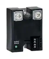
MCSS1225ES
Solid State Relay, Soft Start / Soft Stop, SPST-NO, 25 A, 140 VAC, Panel Mount, Screw
⚠️ Reference pricing provided. In case of supply shortages, we will connect you with our trusted procurement partners to ensure your project's continuity.
- Manufacturer: SENSATA/CRYDOM
- Product type:
- SVHC: No SVHC (21-Jan-2025)
- Load Current: 25A
- Product Range: MCS Series
- Relay Mounting: Panel Mount
- Switching Mode: -
- Relay Terminals: Screw
- Control Voltage Max: 32VDC
- Control Voltage Min: 8VDC
- Contact Configuration: SPST-NO
- Operating Voltage Max: 140VAC
- Operating Voltage Min: 90VAC
| Delivery and price | |
|---|---|
| Units per pack | 1 |
| Price | 131.34 € |
| Current stock | 10+ |
| Lead time | 22 days |
Datasheet

## **| MCS SERIES**

SOFT START/SOFT STOP SOLID STATE RELAY

## Features

- Microcontroller based soft start/soft stop SSR

- Ratings from 25 A to 90 A @ 48-530 VAC

- Low-voltage, current or potentiometer control

- Output status indicator

- Adjustable ramp rates • For use with a wide range of resistive loads

## **PRODUCT SELECTION**

|**Line Voltage**|**25 A**|**50 A**|**90 A**|
|---|---|---|---|
|**120 VAC**|MCST1225|MCST1250|MCST1290|
|**240 VAC**|MCST2425|MCST2450|MCST2490|
|**480 VAC**|MCST4825|MCST4850|MCST4890|


## **SPECIFICATIONS**

## Output (voltage)

|**Description**|**120 VAC**|**240 VAC**|**480 VAC**|
|---|---|---|---|
|**Operating Voltage (47-63Hz) [Vrms]**|48-140|180-280|300-530|
|**Transient Overvoltage [Vpk]**|400|600|1200|
|**Maximum Off-State Leakage Current @ Rated Voltage [mArms]**|5|7|12|
|**Minimum Off-State dv/dt @ Maximum Rated Voltage [V/μsec]**|200|200|200|


Page 1

Copyright © 2024 Sensata Technologies, Inc.

www.sensata.com

## Output (current)

**==> picture [541 x 118] intentionally omitted <==**

**----- Start of picture text -----**<br>
Description 25A 50A 90A<br>Maximum Load Current [Arms] 25 50 90<br>Minimum Load Current [mArms] 150 150 150<br>Maximum Surge Current (16.6 msec) [Apk] 250 625 1200<br>Maximum On-State Voltage Drop @ Rated Current [Vpk] 1.6 1.6 1.6<br>Thermal Resistance Junction to Case (Rjc) [°C/W] 1.02 0.63 0.28<br>Maximum I² t for Fusing (8.3 msec) [A²sec] 260 1620 6000<br>**----- End of picture text -----**<br>


## Input[(1)]

**==> picture [541 x 208] intentionally omitted <==**

**----- Start of picture text -----**<br>
Description DC Control<br>DC Voltage Supply Range (VDC) [P1] 8-32<br>Input Current Range [mA] [P1] 28-30<br>Nominal Input Impedance [Ohm] [P3] 30K<br>Control Must Operate Voltage “On”[VDC][P3] 5-32<br>Control Must Release Voltage “Off” [VDC][P3] 0-4<br>Control Input Current [mA][P3]  0-2.6<br>PLV Range Option A [VDC][P4] 0.5-5<br>PLV Range Option B [VDC][P4] 1.25-7<br>PLV Range Option C [VDC][P4] 2-10<br>PLV Range Option D [VDC][P4] 4-20<br>Nominal Input Impedance Option A,B,C [Ohm][P4] 20K<br>Nominal Input Impedance Option D [Ohm][P4] 220<br>**----- End of picture text -----**<br>


## Output Status Functions

**==> picture [541 x 118] intentionally omitted <==**

**----- Start of picture text -----**<br>
Conditions<br>Initial Logic Supply Flash Once<br>Load Voltage Missing/Load Open (w/control disabled) Flash Once Intermittenly<br>Load Voltage Missing/Load Open (w/control enabled) Off<br>Ramp Time (Soft Start upon P3 Enabled) Off to Bright<br>Ramp Time (Soft Start upon P3 Disabled) Bright to Off<br>Output ON (Normally Steady Operation) On<br>**----- End of picture text -----**<br>


## General

**==> picture [541 x 118] intentionally omitted <==**

**----- Start of picture text -----**<br>
Description Parameters<br>Minimum Power Factor (with Maximum Load) 0.5<br>Dielectric Strength, Input/Output/Base (50/60 Hz) 4000 Vrms<br>Minimum Insulation Resistance (@ 500 VDC) 10 [9]   Ohms<br>Maximum Capacitance, Input/Output 10 pF<br>Ambient Operating Temperature Range  -20 to 80˚C<br>Ambient Storage Temperature Range  -40 to 125˚C<br>**----- End of picture text -----**<br>


Page 2

Copyright © 2024 Sensata Technologies, Inc.

www.sensata.com

**Weight (typical) Encapsulation Terminals-Power Terminals-Control Max. Terminal (Power) Screw Torque**

## 3.0 oz (86.5g)

Thermally Conductive Epoxy Screws and Saddle Clamps Furnished, Unmounted Barrier Strip Screw Terminals 20 lb-in (8-32 screws, dry without grease)

## **MECHANICAL SPECIFICATIONS**

Tolerances: ±0.02 in / 0.5 mm

All dimensions are in inches [millimeters]

**==> picture [371 x 136] intentionally omitted <==**

**----- Start of picture text -----**<br>
Analog Input OPTIONS: A, B, C, D Analog Input OPTIONS: E (Internal Potentiometer)<br>MOUNTING 1.10 MOUNTING 1.10<br>HOLE/SLOT (27.9) 8-32 TERMINAL HOLE/SLOT (27.9) 8-32 TERMINAL<br>0.17 (4.3) DIA. .45 (2 PLACES) 0.17 (4.3) DIA. .45 (2 PLACES)<br>(11.4) (11.4)<br>OUTPUT OUTPUT<br>1/L1 2/T1 1/L1 2/T1<br>2.30 2.30<br>1.87 [58.4] 1.87 [58.4]<br>[47.5] [47.5]<br>P4<br>OUTPUTSTATUS P3 OUTPUTSTATUS P3<br>P2 P2<br>P1 P1<br>.78 .78<br>BASE PL.125(3.2) ATE 1.80 (19.8) BASE PL.125(3.2) ATE 1.80 (19.8)<br>(45.7) “ | n s (45.7) _<br>**----- End of picture text -----**<br>


## **THERMAL DERATE INFORMATION**

**==> picture [525 x 339] intentionally omitted <==**

**----- Start of picture text -----**<br>
25A 50A 90A<br>30 95 60 120 90<br>1 1 .5 95 .2<br>25 2 100 1.5 .5 .4 100<br>20 40 100 80<br>3 2 1<br>15 110<br>110 110<br>10 20 40<br>NO HEATSINK<br>5 120 NO HEATSINK 120 120<br>0 Z S 0 A N 0 7 S<br>51 01 52 02 52 04 06 08 0 10 20 30 40 50 20 40 60 80 20 40 60 80 02 04 06 08 0<br>Load Current (Amps) Max Ambient Temp. (”C) Load Current (Amps) Max Ambient Temp. (”C) Load Current (Amps) Max Ambient Temp. (”C)<br>WIRING DIAGRAM<br>AC<br>me P4<br>+ P1 P2<br>OUTPU T<br>1/L1 2/T1<br>10K - 50K<br>For A,B or C Option<br>OUTPU T<br>STATUS<br>°<br>+<br>P1  8-32Vdc (+)<br>P2  Ground (-)<br>P3  ON/OFF Contro l<br> 0-5V, 0-7V, 0-10V, 4-20mA<br>Note: P2 is also 4-20mA return<br>C) C)<br>C)<br>Power Dissipation<br>Base Plate Temp ( Power Dissipation Base Plate Temp ( Power Dissipation<br>Base Plate Temp (<br>**----- End of picture text -----**<br>


Page 3

Copyright © 2024 Sensata Technologies, Inc.

www.sensata.com

## **RAMP TIME IN SECONDS**

**==> picture [358 x 249] intentionally omitted <==**

**----- Start of picture text -----**<br>
Option S (1 sec) Option S (1 sec)<br>1.1 1.1<br>1.0 1.0<br>0.9 0.9<br>0.8 0.8<br>0.7 0.7<br>0.6 0.6<br>0.5 0.5<br>0.4 0.4<br>0.3 0.3<br>0.2 0.2<br>0.1 0.1<br>0 0<br>0 24 68 10 12 0 48 12 16 20<br>Analog Input Voltage P4 Analog Input Current P4<br>Option A 5Vdc Option B 7Vdc Option C 10Vdc Option D 4-20mA<br>Option M (10 sec) Option M (10 sec)<br>11 11<br>0 0<br>9 9<br>8 8<br>7 7<br>6 6<br>5 5<br>4 4<br>3 3<br>2 2<br>1 1<br>0 0<br>0 24 68 10 12 0 48 12 16 20<br>Analog Input Voltage P4 Analog Input Current P4<br>Option A 5Vdc Option B 7Vdc Option C 10Vdc Option D 4-20m A<br>Ramp Time in Seconds Ramp Time in Seconds<br>Ramp Time in Seconds Ramp Time in Seconds<br>**----- End of picture text -----**<br>


**==> picture [93 x 172] intentionally omitted <==**

**----- Start of picture text -----**<br>
Soft Start<br>100%<br>0%<br>Ramp time<br>Soft Stop<br>100%<br>0%<br>Ramp time<br>Soft Start/Stop<br>100%<br>0%<br>Ramp time Ramp time<br>Load Voltage<br>Load Voltage<br>Load Voltage<br>**----- End of picture text -----**<br>


**ORDERING OPTIONS** Example : MCST2425CS **MC ST 24 25 C S Series MC Product Type ST:** Soft Start **SP:** Soft Stop **SS:** Soft Start/Soft Stop **Operating Voltage 12:** 90-140 Vrms **24:** 180-280 Vrms **48:** 300-530 Vrms **Rated Load Current 25:** 25 Amps **50:** 50 Amps **90:** 90 Amps **Analog Input A:** 0-5 VDC **B:** 0-7 VDC **C:** 0-10 VDC **D:** 4-20 mA **E:** Internal Potentiometer **Ramp Time On/Off S:** 100 msec - 1 sec Required for valid part number For options only and not required for valid part **M:** 1 sec - 10 sec number

NOTE: Not all combinations are available.

Page 4

Copyright © 2024 Sensata Technologies, Inc.

www.sensata.com

## **GENERAL NOTES**

(1) (2) Voltages are reference to GND (Ground = 0 VDC) P2

## **AGENCY APPROVALS & CERTIFICATIONS**

E116949

## **WARNINGS**

RISK OF MATERIAL DAMAGE AND HOT ENCLOSURE

- The product’s side panels may be hot, allow the product to cool before touching

- Follow proper mounting instructions including torque values

- Do not allow liquids or foreign objects to enter this product

**Failure to follow these instructions can result in serious injury, or equipment damage.**

HAZARD OF ELECTRIC SHOCK, EXPLOSION OR ARC FLASH

- Disconnect all power before installing or working with this equipment

- Verify all connections and replace all covers before turning on power **Failure to follow these instructions will result in death or serious injury.**

Page 5

parties (“Buyers”) who are developing systems that incorporate Sensata products (also referred to herein as “components”). Buyer understands and agrees that Buyer remains responsible for using its independent analysis, valuation, and judgment in designing Buyer’s systems and products. Sensata datasheets have been created using standard laboratory conditions and engineering practices. Sensata has not conducted any testing other than that specifically described in the published documentation for a particular datasheet. Sensata may make corrections, enhancements, improvements, and other changes to its datasheets or components without notice. Buyers are authorized to use Sensata datasheets with the Sensata component(s) identified in each particular datasheet. HOWEVER, NO OTHER LICENSE, EXPRESS OR IMPLIED, BY ESTOPPEL OR OTHERWISE TO ANY OTHER SENSATA INTELLECTUAL PROPERTY RIGHT, AND NO LICENSE TO ANY THIRD PARTY TECHNOLOGY OR INTELLECTUAL PROPERTY RIGHT, IS GRANTED HEREIN. SENSATA DATASHEETS ARE PROVIDED “AS IS”. SENSATA MAKES NO WARRANTIES OR REPRESENTATIONS WITH REGARD TO THE DATASHEETS OR USE OF THE DATASHEETS, EXPRESS, IMPLIED, OR STATUTORY, INCLUDING ACCURACY OR COMPLETENESS. SENSATA DISCLAIMS ANY WARRANTY OF TITLE AND ANY IMPLIED WARRANTIES OF MERCHANTABILITY, FITNESS FOR A PARTICULAR PURPOSE, QUIET ENJOYMENT, QUIET POSSESSION, AND NON-INFRINGEMENT OF ANY THIRD PARTY INTELLECTUAL PROPERTY RIGHTS WITH REGARD TO SENSATA DATASHEETS OR USE THEREOF.

All products are sold subject to Sensata’s terms and conditions of sale supplied at www.sensata.com. SENSATA ASSUMES NO LIABILITY FOR APPLICATIONS ASSISTANCE OR THE DESIGN OF BUYERS’ PRODUCTS. BUYER ACKNOWLEDGES AND AGREES THAT IT IS SOLELY RESPONSIBLE FOR COMPLIANCE WITH ALL LEGAL, REGULATORY, AND SAFETY-RELATED REQUIREMENTS CONCERNING ITS PRODUCTS, AND ANY USE OF SENSATA COMPONENTS IN ITS APPLICATIONS, NOTWITHSTANDING ANY APPLICATIONSRELATED INFORMATION OR SUPPORT THAT MAY BE PROVIDED BY SENSATA.

## **CONTACT US**

## **Americas**

+1 (800) 350 2727 sales.crydom@sensata.com

**Europe, Middle East & Africa**

+44 (1202) 416170 ssr-info.eu@sensata.com

##

sales.isasia@list.sensata.com China +86 (21) 2306 1500 Japan +81 (45) 277 7117 Korea +82 (31) 601 2004 India +91 (80) 67920890 Rest of Asia +886 (2) 27602006 ext 2808

Mailing Address: Sensata Technologies, Inc., 529 Pleasant Street, Attleboro, MA 02703, USA.

www.sensata.com

Rev:07/24/2024

Copyright © 2024 Sensata Technologies, Inc.
Updated at June 5, 2026
About Novapart
Novapart is a B2B electronic component broker specialising in stock shortages and cost reduction. We source hard-to-find parts and identify compliant alternatives across a catalogue of 410,000+ components from 500+ manufacturers.
Learn more →Stock Shortage Specialist
When a component is unavailable, discontinued or has an unacceptable lead time, we tap into our network of vetted European and Asian distributors to source what you need — without compromising on quality or traceability.
Request a quote →Compliant Alternatives
We identify pin-to-pin, electrically equivalent substitutes that meet the same certifications (RoHS, AEC-Q100, REACH) as your original specification — validated against datasheets, not just part numbers. Often at a lower cost.
BOM Analysis service →