
Image not available
Illustrative purposes only

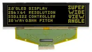
MCOT256064A1A-YM
Graphic OLED, 256 x 64 Pixels, Yellow on Black, 5V, Parallel, Serial, 84mm x 25.8mm, -35 °C
⚠️ Reference pricing provided. In case of supply shortages, we will connect you with our trusted procurement partners to ensure your project's continuity.
- Manufacturer: MIDAS
- Product type: Graphic OLED Displays
- Resolution: 256 x 64 Pixels
- Module Size: 84mm x 25.8mm
- Logic Voltage: 5V
- Interface Type: Parallel, Serial
- Display Appearance: Yellow on Black
- Display Construction: TAB
- Operating Temperature Max: 85°C
- Operating Temperature Min: -35°C
| Delivery and price | |
|---|---|
| Units per pack | 50 |
| Price | 29.62 € |
| Current stock | 10+ |
| Lead time | 30 days |
Datasheet

Electra House, 32 Southtown Road Great Yarmouth, Norfolk NR31 0DU, England

Telephone +44 (0)1493 602602 Fax +44 (0)1493 665111 Email:sales@midasdisplays.com www.midasdisplays.com

**==> picture [408 x 139] intentionally omitted <==**

**----- Start of picture text -----**<br>
MCOT256064A1A-YM 256 x 64 Yellow<br>Specification<br>Version:   4 Date: 03/10/2017<br>Revision<br>1 02/02/2015<br>First Revision.<br>2 02/07/2015 Modify Life Time.<br>3 22/12/2015 Modify Life Time.<br>4 01/06/2016 Modify Static Electricity Test.<br>**----- End of picture text -----**<br>


**==> picture [327 x 71] intentionally omitted <==**

**----- Start of picture text -----**<br>
COCO‘; 256 x 64<br>Yellow on Black<br>Logic Voltage<br>Parallel / Serial<br>Module Size Po 84.00 x 25.80 x 2.05<br>**----- End of picture text -----**<br>


- - For full design functionality, please use this

> ~~[PartNumber] | Description~~ Interface board compatible with any display that requires a direct solder MPBV4-Iss2 connection to 0.7, 0.8 , 0.845 or 1 mm. Supports any driver board that can be wired to a 2mm pitch 44-way DIL.

Green on Black Blue on Black Red on Black

## **Mechanical Specifications**

|**Mechanical Specifications**|**Mechanical Specifications**|**Mechanical Specifications**|**Mechanical Specifications**|**Mechanical Specifications**|**Mechanical Specifications**|
|---|---|---|---|---|---|
|Module Size|84.00 x 25.80 x 2.05 (With��� Backlight)||||W x H x D mm|
|Active Area|69.098 x 17.258|W x H mm|Hole-to-Hole|---|W x H mm|
|Dot Size|0.248 x 0.248|W x H mm|Dot Pitch|0.27 x 0.27|W x H mm|


**==> picture [512 x 583] intentionally omitted <==**

**----- Start of picture text -----**<br>
NC(GND) VSS VCC VCOMH VLSS D7 D6 D5 D4 D3 D2 D1 D0 E/RD# R/W# BS0 BS1 DC# CS# RES# FR IREF NC VDDIO VDD VCI VSL VLSS VCC NC(GND)<br>1 2 3 4 5 6 7 8 9 10 11 12 13 14 15 16 17 18 19 20 21 22 23 24 25 26 27 28 29 30<br>0.3mm.<br>Common B0 (Row 64) Common B63   (Row 1)<br>2.05 Stiffener Segment 240 (Column 129)<br>Segment 357 (Column 256)<br>0.7 1.1<br>Polarizer  Ó0.05 Segment 112 (Column 1)<br>¡ Segment 239 (Column 128)<br>0.3 Common A0 (Row 64) Common A63 (Row 1)<br>7.451 REMOVE TAPE T=0.15Max Contact Side<br>The non-specified tolerance of dimension is<br>2-R0.5¡ Ó0.05<br>30<br>SSD1322U 0.3 40.0¡ Ó0.160.0¡ Ó0.2<br>71.104(VA) 69.098(AA)<br>1 P0.5*29=15.5 0.27 0.248<br>Active Area 2.8" 256*64 Pixels<br>84.0¡ Ó0.3(Panel Size) 84.0¡ Ó0.3(Cap Size) 83.0¡ Ó0.3 (Polarizer)<br>DOT SIZE SCALE 30/1<br>12.0<br> Ó0.5¡ 6.45 7.451<br>0.5<br>4.0<br>0.248<br>0.27<br>3.0<br>4.66<br>2.8 17.258(AA) 9.0<br>1.8 19.264(VA) 9.5<br>0.5¡ Ó0.5 22.8¡ Ó0.3 (Polarizer) 10.62<br>23.8(Cap Size)  Ó0.3¡20.0<br>25.8¡ Ó0.3(Panel Size)<br>**----- End of picture text -----**<br>


|MCOT256064A1A-YM|256 x 64|256 x 64|Yellow|���� Module|
|---|---|---|---|---|
|**Specification**|||||
|Version:   4||Date:  03/10/2017|||
|**Revision**|||||
||||||


|||**Pin layout**|**Pin layout**|**Pin layout**|**Pin layout**||
|---|---|---|---|---|---|---|
|**Pin**|**Symbol**|**Description**||||**Remarks**|
|1|NC|No Connection. Must connect to external Ground.|||||
|2|VSS|**Ground of Logic Circuit.**<br>Ground pin, also acts as a reference for logic pins. Must<br>connect to external ground.|||||
|3|VCC|**Power Supply for OLED Panel.**<br>Most positive voltage supply pin of the chip. They must be<br>connected to external source.|||||
|4|VCOMH|**Voltage Output High Level for COM Signal.**<br>Input pin for the voltage output high level for COM signals. A<br>tantalum capacitor should be connected between this pin and<br>VSS.|||||
|5|VLSS|**Ground of Analogue Circuit.**<br>These are the analogue ground pins. They should be<br>connected to VSS externally.|||||
|6~13|D7~D0|**Host Data Input / Output Bus.**<br>8-bit bi-directional data bus pins to be connected to the<br>microprocessor’s data bus. When serial mode is selected, D1<br>will be the serial data input SDIN and D0 will be the serial<br>clock input SCLK. Unused pins must be connected to VSS<br>except for D2 in serial mode|||||
|14|E/RD#|**Read / Write Enable or Read.**<br>MCU interface input. When interfacing to a 6800<br>microprocessor, this pin will be used as the Enable (E)<br>signal. Read/write operation is initiated when this pin is<br>pulled high and the CS# is pulled low.<br>When connecting to an 8080 microprocessor, this pin<br>receives the Read (RD#) signal. Data read operation is<br>initiated when this pin is pulled low and CS# is pulled low.<br>When serial mode is selected, this pin must be connected to<br>VSS.|||||
|15|R/W#|**Read / Write Select or Write.**<br>MCU interface input. When interfacing to a 6800 series<br>microprocessor, this pin will be used as Read/Write (R/W#)<br>selection input. Pull this pin to “High” for read mode and pull<br>it to “Low” for write mode.<br>When 8080 interface mode is selected, this pin will be the<br>Write (WR#) input. Data write operation is initiated when this<br>pin is pulled low and the CS# is pulled low. When serial<br>mode is selected, this pin must be connected to VSS.|||||
|16|BS0|**Communicating Protocol Select.**<br>MCU interface selection input. See below table:<br>3-Wire SPI: BS0=1 BS1=0<br>4-Wire SPI: BS0=0 BS1=0<br>6800 Parallel: BS0=1 BS1=1<br>8080 Parallel: BS0=0 BS1=1|||||
|17|BS1||||||
|18|D/C#|**Data / Command Control.**<br>When the pin is pulled high, the input at D7~D0 is treated as<br>display data. When the pin is pulled low, the input at D7~D0<br>will be transferred to the command register.|||||
|19|CS#|**Chip Select.**<br>Chip Select Input. The chip is enabled for MCU<br>communication only when CS# is pulled low.|||||
|20|RES#|**Power Reset for Controller and Driver.**<br>Reset signal input. When the pin is low, initialization of the<br>chip is executed.|||||
|21|FR|**Frame Frequency Triggering Signal.**|||||
||||||||
|MCOT256064A1A-YM|||256 x 64||Yellow|����Module|
|||**Specification**|||||
|Version:   4||||Date:  03/10/2017|||
|||**Revision**|||||
||||||||


|||This pin will send out a signal that could be used to identify<br>the driver status. Nothing should be connected to this pin. It<br>should be left open individually.||
|---|---|---|---|
|22|IREF|**Current Reference for Brightness Adjustment.**<br>Segment current reference pin. A resistor should be<br>connected between this pin and VSS. Set the current lower<br>than 10uA.||
|23|NC|No Connection. Reserved for compatible and flexible design.||
|24|VDDIO|**Power Supply for I/O Pin**<br>Power supply pin of I/O buffer. It should be connected to<br>VDD or external source. All I/O signal should have VIH<br>reference to VDDIO. When I/O signal pins (BS0~BS1,<br>D0~D7, control signals…) pull high, they should be<br>connected to VDDIO.||
|25|VDD|**Power Supply for Core Logic Circuit.**<br>Voltage supply pin. It can be supplied externally (within the<br>range of 2.4~2.6V) or regulated internally from VCI. A<br>capacitor should be connected between this pin & VSS under<br>all circumstances.||
|26|VCI|**Power Supply for Operation.**<br>This is a voltage supply pin. It must be connected to external<br>source & always be equal to or higher than VDD & VDDIO.||
|27|VSL|**Voltage Output Low Level for SEG Signal.**<br>This is segment voltage reference pin.<br>When external VSL is not used, this pin should be left open.<br>When external VSL is used, this pin should connect with<br>resistor and diode to ground.||
|28|VLSS|**Ground of Analogue Circuit.**<br>These are the analogue ground pins. They should be<br>connected to VSS externally.||
|29|VCC|**Power Supply for OLED Panel.**<br>Most positive voltage supply pin of the chip. They must be<br>connected to external source.||
|30|NC|No Connection. Must connect to external Ground.||


|MCOT256064A1A-YM|256 x 64|256 x 64|Yellow|����Module|
|---|---|---|---|---|
|**Specification**|||||
|Version:   4||Date:  03/10/2017|||
|**Revision**|||||
||||||


## **Absolute Maximum Ratings**

|**Absolute Maximum Ratings**|**Absolute Maximum Ratings**|**Absolute Maximum Ratings**|**Absolute Maximum Ratings**|**Absolute Maximum Ratings**|**Absolute Maximum Ratings**|**Absolute Maximum Ratings**|**Absolute Maximum Ratings**|
|---|---|---|---|---|---|---|---|
|**Item**<br>~~ee~~|**Symbol**<br>~~ee~~|**Condition**<br>~~cc~~|**Min**<br>~~cc~~|**Typ**<br>~~cc~~|**Max**|**Unit**|**Unit**|
|Power Supply (Logic)<br>~~ee~~|VDD<br>~~ee~~<br>~~2~~|~~cc~~<br>~~2~~|-0.5<br>~~cc~~|---<br>~~cc~~|2.75|V||
|Power Supply (Display)<br>~~ee~~<br>~~re~~|VCC<br>~~ee ~~<br>~~re~~<br>~~2~~|~~cc~~<br>~~re~~<br>~~2~~|-0.5<br>~~cc~~<br>~~re~~|---<br>~~cc~~<br>~~re~~|20.00<br>~~re~~|V<br>~~re~~||
|SupplyOperation Voltage<br>~~re~~|VCI<br>~~re~~<br>~~2~~|---<br>~~re~~<br>~~2~~|-0.3<br>~~re~~|---<br>~~re~~|4.00<br>~~re~~|V<br>~~re~~||
|SupplyVoltage for I/O Pins<br>~~a~~|VDDIO<br>|---<br>|-0.5<br>|---<br>|VCI<br>|V<br>||
|Operating Temperature<br>~~a~~|TOP<br>|---<br>||---<br>||°C<br>||
|Storage Temperature<br>~~aes~~|TSTG<br>~~es~~|---<br>~~es~~|~~es~~|---<br>~~es~~|80<br>~~es~~|°C<br>~~es~~||


|Electronic Characteristics|Electronic Characteristics|Electronic Characteristics|Electronic Characteristics|Electronic Characteristics|Electronic Characteristics|Electronic Characteristics|
|---|---|---|---|---|---|---|
|ltem|Symbol ||| Condition |||Minimum ||| Typical ||| Maximum ||Unit|
|||---|||||
||||||||
|||---|||||
|||---|||0.1xVDDIO||
||||2.80|3.00|3.30||
|Display<br>Supply Voltage for|VCC|—|10.00|12.00|15.00|V|
|Yellow|||45||49||
|Yellow|||8|50|52||
|50% Check Board<br>Operating Current.<br>~~|~~|~~IDD~~|VCI=3.0V|23.00|25.00|32.00|~~na~~<br>~~|~~|


||||||**OLED Characteristics**|**OLED Characteristics**|**OLED Characteristics**|**OLED Characteristics**|||||
|---|---|---|---|---|---|---|---|---|---|---|---|---|
|**Item**||**Symbol**||**Symbol**|**Condition**|**Minimum**|||**Typical**||**Maximum**|**Unit**|
|Viewing Angle||(V)θ<br>(H)φ|||---<br>---|160<br>160|||---<br>---||---<br>---|Deg<br>Deg|
|ContrastRatio||CR|||Dark|2000:1|||---||---|---|
|Response Time|Response Time|T Rise<br>T Fall|||---<br>---|---<br>---|||10<br>10||---<br>---|µs<br>µs|
|Display with 50% check<br>board brightness.|||||---|80|||100||---|Nits|
||||||||||||||
||||||**OLED Life Time**||||||||
|**Item**|||||**Conditions**||**Typical**||||**Remark**||
|Operating Life Time||||Ta=25°C. Initial<br>checkboard brightness,.<br>50,000 Hours|||||0,000 Hours||---||


MCOT256064A1A-YM 256 x 64 Yellow ~~CSS PC —T oY ee~~ **Specification** ~~ate~~ Version:  4 ~~0810/2077 |~~ **Revision**
Updated at February 9, 2023
About Novapart
Novapart is a B2B electronic component broker specialising in stock shortages and cost reduction. We source hard-to-find parts and identify compliant alternatives across a catalogue of 410,000+ components from 500+ manufacturers.
Learn more →Stock Shortage Specialist
When a component is unavailable, discontinued or has an unacceptable lead time, we tap into our network of vetted European and Asian distributors to source what you need — without compromising on quality or traceability.
Request a quote →Compliant Alternatives
We identify pin-to-pin, electrically equivalent substitutes that meet the same certifications (RoHS, AEC-Q100, REACH) as your original specification — validated against datasheets, not just part numbers. Often at a lower cost.
BOM Analysis service →