
Image not available
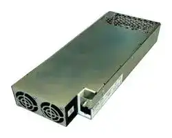
Illustrative purposes only

MBE1200-1T24
AC/DC Enclosed Power Supply (PSU), Medical, 1 Outputs, 1.2 kW, 24 VDC, 50 A
⚠️ Reference pricing provided. In case of supply shortages, we will connect you with our trusted procurement partners to ensure your project's continuity.
- Manufacturer: BEL POWER SOLUTIONS
- Product type: AC / DC Enclosed Power Supplies
- SVHC: To Be Advised
- Product Range: MBE1200 Series
- No. of Outputs: 1Outputs
- Output Power Max: 1.2kW
- Current, Output 4: -
- Input Voltage VAC: 85V AC to 305V AC
- Power Supply Output Type: Adjustable, Fixed
- Output Current - Output 1: 50A
- Output Current - Output 2: -
- Output Current - Output 3: -
- Output Voltage - Output 1: 24VDC
- Output Voltage - Output 2: -
- Output Voltage - Output 3: -
- Output Voltage - Output 4: -
- Power Supply Applications: Medical
| Delivery and price | |
|---|---|
| Units per pack | 1 |
| Price | 656.2 € |
| Current stock | 10+ |
| Lead time | 30 days |
Datasheet

The MBC1200 / MBE1200 Series of AC-DC power supplies provides a steady 1200 W of regulated DC power through 180-305 VAC and 1000 W through 85-137 VAC input voltage ranges in a single output of 24 or 48 VDC, offering 12 and 5 VSB standby outputs and a full set of protection features.

The MBC1200 / MBE1200 Series is available in three compact 1U height compatible packages; one, enclosed with a built-in front mounted pair of fans and two (available only 24 V variant), U-shaped chassis with or without protective cover, to facilitate system integration.

The MBC1200 / MBE1200 Series supports digital power management over the Power Management Bus communications protocol. Multiple units may be connected in parallel for redundancy and / or higher power, enabled with the internal OR-ing and current sharing functions.

The MBC1200 / MBE1200 Series complies with the latest edition of the IEC/EN 60601-1 safety standards for medical equipment requiring 2x MoPP protection grade and displays the CE-Mark for the European Low Voltage Directive (LVD).

- Universal input voltage range

   - 90 – 305 VAC, MoOP; 90 – 264 VAC, MoPP

- Input inrush current limiting

- 1200 W rated power

- High efficiency up to 94%

- Single 24 VDC / 48 VDC output voltages available

- Active PFC, EN61000-3-2 compliant (Class C, >25% load)

- Low earth / touch leakage current

- Fan speed control function

- 800 LFM airflow for MBC1200 models

- Over temperature, OV, OC and SC protections

- +12 V, 0.5 A; +5 V, 1 A Stand by outputs

- Built-in current sharing and OR-ing for parallel operation and N+1 redundancy

- Remote On / Off signal

- Power good and remote sense signals

- Power Management Bus communication protocol supported

- Medical safety approval to IEC 60601-1 3rd edition, 2x MoPP rated and BF appliances compatible

- IEC 60601-1-2 4th edition EMC compliant

- RoHS 3 compliant (Directive 2015/863/EU)

- X-Ray / CT Scanner

- Dental Equipment

- Laboratory / Analysis Equipment

- Medical Devices / Applications

Please read our datasheet & drawing disclaimer here.

MBC1200 / MBE1200 Series

2

|**MODEL NUMBER**|**PACKAGE &**<br>**COOLING**|**INPUT VOLTAGE**<br>**RANGE**<br>**[VAC]**|**INPUT VOLTAGE**<br>**NOM. OUTPUT**<br>**VOLTAGE**<br>**[VDC]**|**MAX. OUTPUT**<br>**POWER**<br>**[W]**|**MAX. OUTPUT**<br>**MAX. OUTPUT**<br>**CURRENT**<br>**[A]**|**MAX. OUTPUT**<br>**DIMENSIONS**|
|---|---|---|---|---|---|---|
|MBC1200-1T24-UCF|U-chassis,<br>external air flow|85 - 305|24|1200|50|101.6 x 234.0 x 41.0 mm<br>4.00 x 9.21 x 1.61 in|
|MBC1200-1T24-PCF|Protective cover,<br>external air flow|85 - 305|24|1200|50|101.6 x 234.7 x 41.0 mm<br>4.00 x 9.24 x 1.61 in|
|MBE1200-1T24|Enclosed,<br>front mounted fan|85 - 305|24|1200|50|101.6 x 264.1 x 41.0 mm<br>4.00 x 10.4 x 1.61 in|
|MBE1200-1T48|Enclosed,<br>front mounted fan|85 - 305|48|1200|25|101.6 x 264.1 x 41.0 mm<br>4.00 x 10.4 x 1.61 in|


|**PARAMETER**|**DESCRIPTION / CONDITION**|**MIN**|**NOM**|**MAX**|**UNIT**|
|---|---|---|---|---|---|
||PS starts at 85 VACat all load conditions|||||
|AC Input Voltage|Operating input voltage range<br>MBC1200 / MBE1200 Series is designed to operate with a square or|85|100-277|100-277<br>305|VRMS|
||trapezoidal input voltage wave form (i.e. from UPS)|||||
|DC Input Voltage|Built in fuses safety certified up to 250 VDC. Operating the 1200 W Series<br>above that limit up to 300 VDC, does require an external fuse protection *|120|-|300|VDC|
|Input Frequency||47|50/60|63|Hz|
|Input Current|At 180 VAC, maximum load, 50 / 60 Hz<br>At 85 VAC, 1000 W load, 50 / 60 Hz<br>163 VDC, maximum load<br>120 VDC, 1000 W|-|-|8.0<br>14.5<br>9.0<br>10.0|ARMS<br>A|
||At power-on asserted|||||
|Inrush Current|Cold start, 25 °C ambient, full load<br>Any point of the AC input sine                         230 VAC<br>277 VAC|-<br>-|-<br>-|30<br>50|A|
|Fusing|High breaking, 16 / 20 A, 277 VAC(250 VDC) on each AC line.|-|-|16 / 20|A|
||20% rated load|88|-|-||
||At 120 VAC<br>50% rated load|92|-|-||
||100% rated load|92|-|-||
|Efficiency|||||%|
||20% rated load|90|-|-||
||At 230 VAC<br>50% rated load|93|-|-||
||100% rated load|94|-|-||
||At power on, no load, 100-277 VACrange (MBE1200-1T24 / -1T48)|-|7.0|-||
|Input Power Consumption|At power on, no load, 100-277 VACrange (MBC1200-1T24-UCF / -PCF)|-|6|-|W|
||Stand by, no load, nominal 100-277 VACrange|-|4.0|-||
|Power Factor|Any nominal input line voltage, 50/60 Hz, from 50 to 100% maximum load|0.95|-|-|-|
|THDi|From 50 to 100% rated load, 100-277 VAC,50/60 Hz.|-|-|20|%|
|Harmonic Current<br>Fluctuations and Flicker|Complies with EN 61000-3-2 at 230 VAC, 50/60 Hz, Class A, D.<br>Complies with EN 61000-3-2 Class C at 230 VAC, 50/60 Hz, >300 W load.<br>Complies with EN 61000-3-3 at nominal voltages and full load.|||||
||Normal conditions|||||
|Earth Leakage Current|115 VRMS, 60 Hz<br>230 VRMS, 50 Hz|-<br>-|130<br>240|-<br>-|µA|
||264 VRMS, 60 Hz (worst case)|-|-|400||
||264 VRMS, 60 Hz|||||
|Touch Leakage Current|Normal Condition (NC)|-|-|100|µA|
||Single Fault Condition (SFC)|-|-|500||
||264 VRMS, 60 Hz|||||
|Patient Leakage Current|Normal Condition (NC)|-|-|100|µA|
||Single Fault Condition (SFC)|-|-|500||


* Suggested fuse SIBA 5012434.16 and fuse holder SIBA 5105805.1

tech.support@psbel.com |

MBC1200 / MBE1200 Series

3

|**PARAMETER**|**DESCRIPTION / CONDITION**||**MIN**|**NOM**|**MAX**|**UNIT**|
|---|---|---|---|---|---|---|
|V1 Output Voltages|±0.5% set point accuracy<br>RS+ closed on +V1, RS- closed on V1 RTN, at 6% load.||-|24<br>48|-|V|
|V1 Output Power Rating|85 – 137 VAC<br>(120-163 VDC)<br>MBC1200-1T24-UCF / -PCF (800 LFM);<br>MBE1200-1T24 / MBE1200-1T48<br>180 – 305 VAC<br>(163-300 VDC)<br>MBC1200-1T24-UCF / -PCF (800 LFM);<br>MBE1200-1T24 / MBE1200-1T48||||1000<br>1200|W|
||85 – 137 VAC<br>MBC1200-1T24-UCF / -PCF; MBE1200-1T24||||41.7||
|V1 Output Current|(120-163 VDC)<br>MBE1200-1T48<br>180 – 305 VAC<br>MBC1200-1T24-UCF / -PCF; MBE1200-1T24||||20.8<br>50|A|
||(163-300 VDC)<br>MBE1200-1T48||||20||
|V1 Voltage Adjustment Range|Manually by push up and down buttons||-|±5|-|%V1|
|V1 Line Regulation|VAC:   85 – 305 VRMS||-|-|±0.1|%V1|
|V1 Load-Line-Cross Regulation|VAC:   85 – 305 VRMS; I1: 0 – 100%||-|-|±2|%V1|
|V1 Ripple and Noise|Rated load, Peak-to-peak, 20 MHz BW.<br>(100 nF ceramic, 10 µF tantalum at load)||-|-|1|%V1|
|Transient Response:|25% load changes at 1 A/µs||||||
|V1, 12VSB, 5VSB<br>Voltage Deviation|24 V at 1000 µF load / IOUT> 2.5 A<br>48 V at 560 µF load / IOUT> 1.25 A||-|-|±5|%V1<br>%VSB|
||12 VSB, 5 VSBat 0-2200 µF load||||||
|V1 Start-up Rise Time|85<VIN<305, any load conditions.||10|-|150|ms|
||At nominal VIN, full load||10|-|-||
||SEMI F47-0706 compliant at≥208 VAC||||||
|V1 Hold-up Time||50% sag (104 V)|200|-|-|ms|
|||30% sag (145 V)|500|-|-||
|||20% sag (166 V)|1000|-|-||
||Parallel operation up to four units.||||||
||Two units in parallel at I1 rated load.||||||
|V1 Current Sharing Accuracy|I-Share signals connected together.<br>RS+, RS-signals connected together and to the load.||40|-|60|%I1|
||Max load at start up 1200 W, operating 2000 W, 180 ÷305 V|Max load at start up 1200 W, operating 2000 W, 180 ÷305 VAC.|||||
||Max load at start up 1000 W, operating 1667 W, 85 ÷ 137 V|Max load at start up 1000 W, operating 1667 W, 85 ÷ 137 VAC.|||||
|V1 Remote Sense|RS+and RS-power path voltage loss compensation||-|-|0.36|V|
||V1 in regulation after de-asserting PS_Inhibit||-|-|1700||
||V1 in regulation after AC is applied||-|-|2200||
|Start-up Delay|(worst case: 85 VAC)|||||ms|
||5VSBin regulation after AC is applied||-|-|500||
||(worst case: 85 VAC)||||||
|Turn-on Overshoot|||-<br>-|-<br>-|10<br>10|%V1<br>%VSB|
|Minimum Load|V1, 12VSB, 5VSB||0|-|-|A|
|Maximum Load Capacitance|V1: 24 VDC<br>V1: 48 VDC||-<br>-|-<br>-|16000<br>8000|µF|
|V1 Over Current Protection|V1: 24 VDC<br>V1: 48 VDC||||75<br>37.5|A|
|12 VSBOutput Voltage|VSBoutput voltage is referred to the same V1 output voltage return||-|12|-|V|
|12 VSBOutput Current|All models up to 70 °C||-|-|0.5|A|
|12 VSBRipple & Noise|Peak-to-peak||||120|mV|
|12 VSBLine Cross Regulation|VAC: 85 – 305 VRMS; ISB: 0 – 100%||-|-|±5|%VSB|
|5 VSBOutput Voltage|VSBoutput voltage is referred to the same V1 output voltage return||-|5|-|V|
|5 VSBOutput Current|All models up to 70 °C||-|-|1|A|
|5 VSBRipple & Noise|Peak-to-peak||||50|mV|
|5 VSBLoad, line cross Regulation|VAC: 85 – 305 VRMS; ISB: 0 – 100%||-|-|±5|%VSB|


**==> picture [51 x 30] intentionally omitted <==**

**----- Start of picture text -----**<br>
rete st<br>c@%SO ee,<br>**----- End of picture text -----**<br>


**Asia-Pacific Europe, Middle East North America** +86 755 298 85888 +353 61 49 8941 +353 61 49 8941

© 2022 Bel Power Solutions & Protection

BCD.01054_C

4

## MBC1200 / MBE1200 Series

Front Fan (Models MBE1200-1T24 / MBE1200-1T48) Any orientation, V1 nominal

## U-Chassis and Perforated Cover

Forced Air Cooling (Models MBC1200-1T24-UCF / -PCF) Air flow from top, V1 nominal

## U-Chassis and Perforated Cover

Forced Air Cooling (Models MBC1200-1T24-UCF / -PCF) Air flow from AC side, V1 nominal

**==> picture [17 x 10] intentionally omitted <==**

**----- Start of picture text -----**<br>
baa<br>**----- End of picture text -----**<br>


tech.support@psbel.com

MBC1200 / MBE1200 Series

5

The MBC1200 / MBE1200 Series does support communication according to the Power Management Bus 1.2 protocol via SDA, SCL and #SMBALERT signals as defined in the SMBus Specification version 2.0.

The power supply shall not load the SMBus if it has no input power (SCL & SDA lines should go to High-Z).

The pull-up resistors (2.2 k Ω ) for these signals shall be external to the power supply and referenced to an external +3.3 V bus voltage.

The DSP circuits inside the power supply are powered by the standby output.

The Power Management Bus is active whatever input power is applied to the power supply or a parallel redundant power supply in the system, provided that their 12VSB are connected in parallel.

Maximum speed of SMBus is 100 kHz.

The ADDR0 and ADDR1 signals, are inputs to the power supply that control the Power Management Bus address assigned to the power supply.

On the system side, the ADDR0 and ADDR1 signals will either be connected to return through a 1 k Ω pull-down resistor or connected to +3.3 V external bus voltage through a 1 k Ω pull-up resistor.

The address shall be derived from the logic of this pin as indicated on Outline Drawing and Connections section. The power supply is a slave only on SMBus device.

For a comprehensive description of MBC1200 / MBE1200 Series Power Management Bus management, do refer to the application note, “MBC1200 / MBE1200 Series Power Management Bus Mgt”. Examples of 1200 W Series parameters available through communication bus are:

- Input voltage status

- Output voltages +V1 measured value

- Output current on +V1 measured value

- Current sharing status

- Thermal health measured value

- Fan health status

- Power-On / Working hours

- Product information

- Status information

Failures shall be reported by Power Management Bus for all failure types:

- Fan fault

- Protections failure (OV, OC, OT)

- Voltages out of specification

## meeeeya bel SOLUTIONSPOWER &

**Asia-Pacific Europe, Middle East North America** +86 755 298 85888 +353 61 49 8941 +353 61 49 8941

© 2022 Bel Power Solutions & Protection

BCD.01054_C

6

## MBC1200 / MBE1200 Series

Base signals and controls are accessible from signal connector P204.

|**SIGNAL**|**DESCRIPTION / CONDITION**|**MIN**||**NOM**|**MAX**|**UNIT**|
|---|---|---|---|---|---|---|
|+PS_Inhibit<br>(Active High)|Input low voltage (IIN= 0 µA)<br>Input high voltage (IIN= 500 µA at 5.5 V)<br>V1 disabled when PS_Inhibit is pulled high<br>V1 enabled when PS_Inhibit is floating or low|0<br>2.5||-<br>-|0.8<br>5.5|V|
||5VSBand 12VSBnot affected by PS_Inhibit||||||
||Input low voltage  (IIN= -800 µA at 0 V)<br>Input high voltage (IIN= -200 µA at 2.5 V)|0<br>2.5||-<br>-|0.8<br>5.5|V|
|-PS_Inhibit|(IIN= 700 µA at 5.5 V)||||||
|(Active Low)|V1 disabled when -PS_Inhibit is pulled low||||||
||V1 enabled when -PS_Inhibit is floating or high||||||
||5VSBand 12VSBnot affected by -PS_Inhibit||||||
||Logic level low (<10 mA sinking)|-||-|0.7|V|
|Power_OK *|Logic level high (200 µA sourcing)|2.4||-|3.45||
|(PS_OK)|Low to high time after V1 in regulation<br>Power down warning time|150<br>2||-<br>-|350<br>-|ms|
||The I_SHARE signals shall be daisy chained among power supplies operating in parallel.||||||
|I_Share|On a single power supply operating it provides current measurement on V1 output.||||||
||On multiple power supplies operating in parallel, it provides current measurement on master V1output.||On multiple power supplies operating in parallel, it provides current measurement on master V1output.||||
|SDA, SCL, #SMBALERT,|These are signals which support Power Management Bus communication protocol as specified in the application||||||
|ADDR0, ADDR1|note MBC1200 / MBE1200 Series Power Management Bus Mgt.||||||
||Mainly intended for internal use, these RX and TX signals - available at the output signal connector||||||
|RSVD RX, RSVD TX|P204 - may be used to access some DSP functions (monitoring, threshold settings, debug functions).<br>These signals work as an UART Rx/Tx port and can also work as a RS-232 Rx/Tx port by building in the||||||
||“RS-232 LINE DRIVERS/RECEIVERS” IC||||||
|5VSBOutput **|Active and in regulation after an 85<VAC<305 is applied<br>Not affected by PS_Inhibit. Available on P204, pin#4|-||-|500|ms|
|12VSBOutput ***|Active and in regulation after an 85<VAC<305 is applied<br>Not affected by PS_Inhibit. Available on P204, pin#16|-||-|500|ms|


* When V1 is On, a P_OK low may indicates V1 under voltage condition. When two 1200 W models operate in parallel, P_OK low in one unit indicates that it is not sharing the expected amount of current (current sharing fault). A 3.3 k Ω internal pull up to a 3.3 V internal reference voltage is used; do not add any other external pull up.

** The 5VSB outputs of two or more 1200 W models operating in parallel, cannot be connected in parallel in turn, since doing so results in power supplies damage.

*** The 12VSB outputs of two or more 1200 W models operating in parallel can be connected in parallel in turn, taking into account that the maximum available power will not be higher of a single operating power supply one.

tech.support@psbel.com

7

## MBC1200 / MBE1200 Series

## 5.1 BASE SIGNALS / CONTROLS TIMING

## **AC/DC INPUT OFF-TO-ON AND ON-TO-OFF TIMINGS**

12VSB/5VSB On to V1 On 250 ms ≤ T1 ≤ 1700 ms V1 rise time 10 ms ≤ T2 ≤ 150 ms 12VSB/5VSB rise time 3 ms ≤ T10 ≤ 150 ms V1 On – POWER_OK delay 150 ms ≤ T3 ≤ 350 ms Power down warning T4 ≥ 2 ms V1 Off to 12VSB/5VSB Off T5 ≥ 0.5 s (V1 load > 25 W) AC Off to POWER_OK low T6 ≥ 8 ms AC_On to 12VSB/5VSB On T7 ≤ 500 ms

## **PS_INHIBIT OFF-TO-ON AND ON-TO-OFF TIMINGS**

V1 rise time 10 ms ≤ T2 ≤ 150 ms V1 On – POWER_OK delay 150 ms ≤ T3 ≤ 350 ms Turn-Off warning T11 ≥ 1 ms PS_Inhibit – POWER_OK low delay T8 ≤ 3 ms PS_Inhibit – V1 On delay T9 ≤ 1700 ms

**==> picture [205 x 35] intentionally omitted <==**

**----- Start of picture text -----**<br>
AREER » POWER<br>Fe.Sain, bel SOLUTIONSPROTECTION &<br>**----- End of picture text -----**<br>


**Asia-Pacific Europe, Middle East North America** +86 755 298 85888 +353 61 49 8941 +353 61 49 8941

© 2022 Bel Power Solutions & Protection

BCD.01054_C

8

## MBC1200 / MBE1200 Series

|**PARAMETER**|**DESCRIPTION / CONDITION**|**MIN**|**NOM**|**MAX**|**UNIT**|
|---|---|---|---|---|---|
|Input Under Voltage|Auto-recovering, hiccup mode.|58|75|82|VAC|
|Input Fuse|High breaking, 16 / 20 A, 277 VAC(250 VDC)<br>on each AC lines.|-|-|16/20|A|
||At nominal input voltages|||||
|Over Current|V1: Hiccup mode, auto-recovering<br>5VSB: Auto-recovering|-<br>-|-<br>-|150<br>-|%I1Rated<br>A|
||12VSB: Hiccup mode, auto-recovering|-|-|-|A|
||At nominal input voltages|||||
|Short Circuit|V1: Hiccup mode or latch<br>5VSB: Auto-recovery|-|-|-||
||12VSB: Hiccup mode, auto-recovering.|||||
|Over Voltage|V1, Power shut down, latch off.<br>12VSB, Hiccup mode, auto-recovering.|116<br>-|-<br>-|145<br>150|%VNOM|
|Over Temperature<br>(ambient)|Hiccup mode, auto-recovering.|70|-|-|°C|
|Over Temperature<br>(on secondary side)|Hiccup mode, auto-recovering.|-|-|-|°C|
||Relevant to the MBE1200-1T24 / MBE1200-1T48 models.|||||
||The DSP monitors the signals (frequency generator) provided by both fans. If one fan fails, the DSP asserts||||The DSP monitors the signals (frequency generator) provided by both fans. If one fan fails, the DSP asserts|
|Fan Fault Protection|maximum speed the other fan and provides an alarm indication through Power Management Bus.<br>If both fans fail, the DSP provides an alarm indication through LED and through Power Management Bus and|||||
||after 20 s, does shut down V1.|||||
||PS INHIBIT or AC/DC input have to be cycled to resume operations, after removed the fault.|||||
|Isolation: Primary-to-Secondary|Reinforced|5660<br>4000|-<br>-|-<br>-|VDC<br>VAC|
|Isolation: Input-to-Earth|Basic<br>Production tested at 2642 VDC|2642<br>1865|-<br>-|-<br>-|VDC<br>VAC|
|Isolation: Output-to-Earth|Basic|1500|-|-|VAC|
|Means of Protection:|2x MoPP (IEC 60601-1 3rd edition) at 90 – 264 VAC, 50/60 Hz (120-300 VDC) up to 4000 m|||2x MoPP (IEC 60601-1 3rd edition) at 90 – 264 VAC, 50/60 Hz (120-300 VDC) up to 4000 m||
|Primary to secondary|2x MoOP (IEC 60601-1 3rd edition) at 90 – 305 VAC, 50/60 Hz (120-300 VDC) up to 4000 m|||||
|Means of Protection:|1x MoPP (IEC 60601-1 3rd edition) at 90 – 264 VAC, 50/60 Hz (120-300 VDC) up to 4000 m|||1x MoPP (IEC 60601-1 3rd edition) at 90 – 264 VAC, 50/60 Hz (120-300 VDC) up to 4000 m||
|Input to Protection Earth|1x MoOP (IEC 60601-1 3rd edition) at 90 – 305 VAC, 50/60 Hz (120-300 VDC) up to 4000 m|||||
|Means of Protection:|1x MoPP (IEC 60601-1 3rd edition) at 100 – 250 VAC, 50/60 Hz up to 4000 m|||||
|Output to Protection Earth||||||
|Equipment Protection Class|Class I, compatible with BF (Body Floating) ME (Medical Equipment)|||||


|**PARAMETER**|**DESCRIPTION / CONDITION**|**MIN**|**NOM**|**MAX**|**UNIT**|
|---|---|---|---|---|---|
||No derating up to 60 °C (MBE1200) and up to 55 °C (MBC1200)|-20|-|60||
|Operating Temperature Range|See derating curves above||||°C|
||MBC1200 / MBE1200 Series starts at -40 °C upon warm up delay|||||
|Operating Temperature Range<br>with Derating|See derating curves and conditions in the Output Specifications<br>section|-|-|70|°C|
|Storage Temperature<br>Transportation Temperature|As per IEC/EN 60721-3-1 Class 1K4<br>As per IEC/EN 60721-3-2 Class 2K4|-40|-|85|°C|
|Humidity|RH, Non-condensing Operating.<br>Non-operating|-|-|90<br>95|%<br>%|
|Operating Altitude|MoPP (90 – 264 VAC, 50/60 Hz, 120 – 300 VDC)<br>MoOP (90 – 305 VAC, 50/60 Hz)<br>Power derating above 1800 m|-<br>-|-<br>-|4000<br>4000|m|
||**EN 60068-2-27**|||||
|Shock|Operating:           Half sine, 30 g, 18 ms, 3 axes, 6x each (3 positive and 3 negative).|||||
||Non-Operating:   Half sine, 50 g, 11 ms, 3 axes, 6x each (3 positive and 3 negative).|||||
||**EN 60068-2-64**|||||
|Vibration|Operating:           Sine,10 – 500 Hz, 1 g, 3 axes, 1 oct/min., 60 min.<br>Random, 5 – 500 Hz, 0.02 g2/Hz, 1 gRMS, 3 axes, 30 min.||, 3 axes, 30 min.|||
||Non-Operating:   5 – 500 Hz, 2.46 gRMS(0.0122 g2/Hz), 3 axes, 30 min.|/Hz), 3 axes, 30 min.||||


**==> picture [204 x 36] intentionally omitted <==**

**----- Start of picture text -----**<br>
re.eZsees  bel SOLUTIONSPOWERPROTECTION&<br>**----- End of picture text -----**<br>


tech.support@psbel.com .

9

## MBC1200 / MBE1200 Series

Full load, 25 °C ambient, 100% duty cycle, 700000 - - Hours MTBF Full load, 40 °C ambient, 75% duty cycle 600000 - - Telcordia SR-332 Issue 2 Useful Life Nominal VIN, 80% load, 40 °C ambient (IPC9592) - 7 - Years

|**PARAMETER**|**DESCRIPTION / CONDITION**|**STANDARD**|**PERFORMANCE**<br>**CLASS**|
|---|---|---|---|
|Conducted|115, 230 VRMS, Maximum load|EN 60601-1-2 (Medical)|B|
|Radiated||EN 60601-1-2 (Medical)|B *|
|Line Voltage Fluctuation & Flicker|Line Voltage Fluctuation & Flicker<br>At 20%, 50% and 100% maximum load<br>Nominal input voltages|EN 61000-3-3||
|Harmonic Current Emission|230 VAC input voltage, 50 / 60 Hz<br>230 VAC  50 / 60 Hz, >300 W load|EN 61000-3-2<br>EN 61000-3-2|A, D<br>C|


* Performance referred to the enclosed package with additional HF chokes on input, output power and signal cables. Radiated emission relevant to the UCF and PCF package variants, should be assessed at system level.

|**PARAMETER**|**DESCRIPTION / CONDITION**|**STANDARD**|**TEST LEVEL**|**CRITERIA**|
|---|---|---|---|---|
||Reference standard for the medical version|EN 60601-1-2, 4th Edition|||
|ESD|15 kV air discharge, 8 kV contact,<br>at any point of the system.|EN 61000-4-2|4|A|
|Radiated Field|10 V/m, 20 – 2700 MHz, 1 kHz, 80% AM|EN 61000-4-3|3|A|
|Electric Fast Transient|±2 kV on AC power port for 1 minute|EN 61000-4-4|3|A|
|Surge|±2 kV line to line; ± 4 kV line to earth on AC power port|±2 kV line to line; ± 4 kV line to earth on AC power port<br>EN 61000-4-5|4|A|
|Conducted RF Immunity|10 VRMS, 0,15 – 80 MHz, 1 kHz, 80% AM|EN 61000-4-6|3|A|
|Dips and Interruptions|200 – 264 VAC:<br>Drop-out to 0% for 10 ms<br>Dip to 40% for 5 cycles (100 ms)<br>Dip to 70% for 25 cycles (500 ms)<br>Drop-out to 0% for 5 s|EN61000-4-11<br>EN61000-4-11<br>EN61000-4-11<br>EN61000-4-11||A *<br>A (derate to 900 W)<br>A<br>B|
||100 – 127 VAC:<br>Drop-out to 0% for 10 ms<br>Dip to 40% for 5 cycles (100 ms)<br>Dip to 70% for 25 cycles (500 ms)<br>Drop-out to 0% for 5 s|EN 61000-4-11<br>EN 61000-4-11<br>EN 61000-4-11<br>EN 61000-4-11||A *<br>A (derate to 400 W)<br>A (derate to 700 W)<br>B|


- Performance referred to +5VSB, +12VSB and V1 (PS_OK goes to low level after 8 ms as per timing described at page 8

## 10. SAFETY AGENCIES APPROVALS

|**CERTIFICATION BODY**|**SAFETY STANDARDS**|**CATEGORY**|
|---|---|---|
|CSA / UL|CSA C22.2 No.60601-1, ANSI/AAMI ES60601-1 3rd Edition + A1|Medical|
||IEC/EN 60601-1 3rd edition+A1|Medical|
||Directive 93/42/CEE: Safety Requirement of the Medical Device|Medical|
||Directive 2014/30/EU: Electromagnetic Compatibility (EMC)||
||Directive 2015/863/EU: RoHS 3||
||Meets all essential requirements of the standard IEC/EN/UL/CSA 61010-1 2nd edition||


**==> picture [205 x 38] intentionally omitted <==**

**----- Start of picture text -----**<br>
HORsees  bel SOLUTIONSPOWER  &<br>**----- End of picture text -----**<br>


**Asia-Pacific Europe, Middle East North America** +86 755 298 85888 +353 61 49 8941 +353 61 49 8941

© 2022 Bel Power Solutions & Protection

BCD.01054_C

MBC1200 / MBE1200 Series

10

## 11. CONNECTIONS AND PIN DESCRIPTION

|**CONNECTIONS**<br>**CONNECTOR**<br>**REFERENCE**<br>**FUNCTION**<br>~~ee~~|**CONNECTIONS**<br>**CONNECTOR**<br>**REFERENCE**<br>**FUNCTION**<br>~~ee~~|**CONNECTIONS**<br>**CONNECTOR**<br>**REFERENCE**<br>**FUNCTION**<br>~~ee~~|**CONNECTIONS**<br>**CONNECTOR**<br>**REFERENCE**<br>**FUNCTION**<br>~~ee~~|**CONNECTIONS**<br>**CONNECTOR**<br>**REFERENCE**<br>**FUNCTION**<br>~~ee~~|**CONNECTIONS**<br>**CONNECTOR**<br>**REFERENCE**<br>**FUNCTION**<br>~~ee~~|
|---|---|---|---|---|---|
|**AC Input Connections**|**P1:**AMTEK TB25C-B02P-13-00A-L|1||Line 1||
||M4 GROUND STUD|2||Line 2||
|||3||Protection Earth||
|||||||
|**DC Input Connections**|**P200, P201, P202, P203:**<br>BRASS M4 THREADED TERMINALS|P200|**24 V Optional**<br>**24 / 48 V**<br>+V1<br>+V1<br>~~ee~~|||
||(tight to 0.8-1 Nm,<br>max. deep screws 7 mm)|P201||+V1|-|
|||P202||V1 RTN|V1 RTN|
|||P203||V1 RTN|-|
|||||||
|**Signal Connector**|**P204:**|1||RMT (-)||
||MOLEX 501876-1640|2||RMT (+)||
|||3||I-SHARE||
|||4||+5VSB||
|||5||PS_INHIBIT||
|||6||PS_OK||
|||7||SCL||
|||8||SDA||
|||9||#SMBALERT||
|||10||ADDR0||
|||11||-PS_INHIBIT||
|||12||ADDR1||
|||13||RSVD_RX (OUT)||
|||14||RSVD_TX (OUT)||
|||15||RTN||
|||16||+12VSB||
|||||||
|**Additional Control Functions**||SW600||V1_ADJ (UP)||
|||SW601||V1_ADJ (DOWN)||
|||DL600||Bi-colour LED||
|||Off||No AC/DC input power provided||
|||Blinking Green||Input power good, standby active,|Input power good, standby active,|
|||||V1 inhibited||
|||Steady Green||V1 Active||
|||Steady or Blinking red||Power Supply Fault||


## 12. MECHANICAL SPECIFICATIONS

|**PARAMETER**|**DESCRIPTION / CONDITION**|
|---|---|
||1150 g (2.53 lb) – MBC1200-1T24-UCF|
|Weight|1250 g (2.75 lb) – MBC1200-1T24-PCF|
||1550 g (3.42 lb) – MBE1200-1T24 / MBE1200-1T48|
||101.6 x 234.0 x 41.0 mm (4.00 x 9.21 x 1.61 in) – MBC1200-1T24-UCF|
|Overall Dimensions|101.6 x 234.7 x 41.0 mm (4.00 x 9.24 x 1.61 in) – MBC1200-1T24-PCF|
||101.6 X 264.1 x 41.0 mm (4.00 x 10.4 x 1.61 in) – MBE1200-1T24 / MBE1200-1T48|


tech.support@psbel.com

11

## MBC1200 / MBE1200 Series

Figure 1. Mechanical Drawing - MBC1200-1T24-UCF Model

Figure 2. Front View - MBC1200-1T24-UCF Model

Figure 6. Rear View - MBC1200-1T24-UCF Model

**==> picture [32 x 28] intentionally omitted <==**

**----- Start of picture text -----**<br>
i @<br>**----- End of picture text -----**<br>


**Asia-Pacific Europe, Middle East North America** +86 755 298 85888 +353 61 49 8941 +353 61 49 8941

© 2022 Bel Power Solutions & Protection

BCD.01054_C

12

## MBC1200 / MBE1200 Series

Figure 4. Mechanical Drawing - MBC1200-1T24-PCF Model

Figure 5. Front View - MBC1200-1T24-PCF Model

Figure 6. Rear View - MBC1200-1T24-PCF Model

**==> picture [52 x 33] intentionally omitted <==**

**----- Start of picture text -----**<br>
eSct © #5<br>**----- End of picture text -----**<br>


tech.support@psbel.com

13

## MBC1200 / MBE1200 Series

Figure 7. Mechanical Drawing - MBE1200-1T24 / MBE1200-1T48 Models

Figure 8. Front View - MBE1200-1T24 / MBE1200-1T48 Models

Figure 9. Rear View - MBE1200-1T24 / MBE1200-1T48 Models

**Asia-Pacific Europe, Middle East North America** +86 755 298 85888 +353 61 49 8941 +353 61 49 8941

© 2022 Bel Power Solutions & Protection

BCD.01054_C

14

## MBC1200 / MBE1200 Series

**NUCLEAR AND MEDICAL APPLICATIONS** - Products are not designed or intended for use as critical components in life support systems, equipment used in hazardous environments, or nuclear control systems.

**TECHNICAL REVISIONS** - The appearance of products, including safety agency certifications pictured on lMBEls, may change depending on the date manufactured. Specifications are subject to change without notice.

**==> picture [51 x 39] intentionally omitted <==**

**----- Start of picture text -----**<br>
wer.ASRS »<br>TH Ang<br>**----- End of picture text -----**<br>


tech.support@psbel.com
Updated at June 4, 2026
About Novapart
Novapart is a B2B electronic component broker specialising in stock shortages and cost reduction. We source hard-to-find parts and identify compliant alternatives across a catalogue of 410,000+ components from 500+ manufacturers.
Learn more →Stock Shortage Specialist
When a component is unavailable, discontinued or has an unacceptable lead time, we tap into our network of vetted European and Asian distributors to source what you need — without compromising on quality or traceability.
Request a quote →Compliant Alternatives
We identify pin-to-pin, electrically equivalent substitutes that meet the same certifications (RoHS, AEC-Q100, REACH) as your original specification — validated against datasheets, not just part numbers. Often at a lower cost.
BOM Analysis service →