
Image not available
Illustrative purposes only

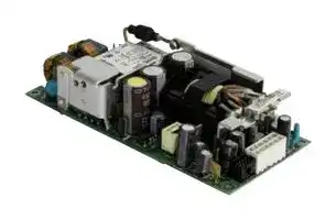
MBC401-1024
AC/DC Open Frame Power Supply (PSU), Medical, 1 Output, 400W @ 400LFM, 250 W, 90V AC to 264V AC
⚠️ Reference pricing provided. In case of supply shortages, we will connect you with our trusted procurement partners to ensure your project's continuity.
- Manufacturer: BEL POWER SOLUTIONS
- Product type: AC / DC Open Frame Power Supplies
- SVHC: To Be Advised
- Product Range: MBC401 Series
- No. of Outputs: 1 Output
- Current, Output 4: -
- Input Voltage VAC: 90V AC to 264V AC
- Power Supply Output Type: Adjustable, Fixed
- Output Current - Output 1: 16.7A
- Output Current - Output 2: -
- Output Current - Output 3: -
- Output Voltage - Output 1: 24VDC
- Output Voltage - Output 2: -
- Output Voltage - Output 3: -
- Output Voltage - Output 4: -
- Power Supply Applications: Medical
- Power Rating (Forced Cooling): 400W @ 400LFM
- Power Rating (Convection Cooling): 250W
| Delivery and price | |
|---|---|
| Units per pack | 5 |
| Price | 218.65 € |
| Current stock | 10+ |
| Lead time | 30 days |
Datasheet

The MBC401 Series of AC-DC power supplies provides up to 400 W of regulated output power through wide input voltage range 90 – 264 VAC in single outputs of 12, 24, 28, 36 or 48 VDC. The MBC401 Series comes in five different low-profile packages, offering 12 and 5 VSB standby outputs and a full set of protection features. Available control signals include Power Good (P_OK), Remote On/Off (PS_ON) and remote sense compensation on the (+) load line. The MBC401 Series complies with the latest international safety standards for medical equipment, offers 2xMoPP means of patient > protection, is suitable for BF rated applied parts and displays the CE-Mark for the European Low Voltage Directive (LVD). —— Key Features & Benefits • Universal input voltage range (90 – 264 VAC) a EG •• Active PFC, EN 61000-3-2 Class C compliant400 W rated output power (440 W peak) • High efficiency (94% typical) • Low stand by power consumption (<0.5 W) • 12, 24, 28, 36, 48 VDC standard output voltages • +5V stand by, 2 A and 12 V auxiliary, 1 A outputs • Low earth leakage current • Fan speed control function (Off at <50 W) • Over temperature protection • Over current and short circuit protection • Remote On/Off and power good signal • 5 available packages all fit 1U installation a • IEC/EN 60601-1 3rd ed. compliant • ANSI/AAMI ES60601-1 3rd ed. compliant • 4000 m operation without de-rating Applications RolniS • Diagnostic equipment • Imaging equipment • Respiratory devices • Therapy appliances • Dental equipment Wis CE

- Dermatology aesthetic medicine

MBC401 Series

**==> picture [491 x 693] intentionally omitted <==**

**----- Start of picture text -----**<br>
||||||||
|---|---|---|---|---|---|---|
|2|
|MODEL|SELECTION|
|INPUT VOLTAGE|NOM. OUTPUT|MAX. OUTPUT|MAX. OUTPUT|
|MODEL NUMBER|PACKAGE & COOLING|RANGE|VOLTAGE|POWER|CURRENT|DIMENSIONS|
|[VAC]|[VDC]|[W]|[A]|
|MBC401-1012|Open Frame|90 - 264|12|400|33.3|76.0 x 164.2 x 37.7 mm|
|Convection / Forced Air|(2.99 x 6.46 x 1.48 in)|
|U-Chassis|84.4 x 166.5 x 40.0 mm|
|MBC401-1012-UC|90 - 264|12|400|33.3|
|Convection / Forced Air|(3.32 x 6.55 x 1.57 in)|
|Perforated Cover|84.4 x 166.5 x 41.0 mm|
|MBC401-1012-PC|90 - 264|12|400|33.3|
|Convection / Forced Air|(3.32 x 6.55 x 1.61 in)|
|Vented Cover|84.4 x 183.0 x 41.0 mm|
|MBC401-1012-T|90 - 264|12|400|33.3|
|Top Fan|(3.32 x 7.20 x 1.61 in)|
|Enclosed|84.4 x 183.0 x 41.0 mm|
|MBC401-1012-S|90 - 264|12|400|33.3|
|Front Mounted Fan|(3.32 x 7.20 x 1.61 in)|
|MBC401-1024|Open Frame|90 - 264|24|400|16.7|76.0 x 164.2 x 37.7 mm|
|Convection / Forced Air|(2.99 x 6.46 x 1.48 in)|
|U-Chassis|84.4 x 166.5 x 40.0 mm|
|MBC401-1024-UC|90 - 264|24|400|16.7|
|Convection / Forced Air|(3.32 x 6.55 x 1.57 in)|
|Perforated Cover|84.4 x 166.5 x 41.0 mm|
|MBC401-1024-PC|90 - 264|24|400|16.7|
|Convection / Forced Air|(3.32 x 6.55 x 1.61 in)|
|Vented Cover|84.4 x 183.0 x 41.0 mm|
|MBC401-1024-T|90 - 264|24|400|16.7|
|Top Fan|(3.32 x 7.20 x 1.61 in)|
|Enclosed|84.4 x 183.0 x 41.0 mm|
|MBC401-1024-S|90 - 264|24|400|16.7|
|Front Mounted Fan|(3.32 x 7.20 x 1.61 in)|
|U-Chassis|84.4 x 166.5 x 40.0 mm|
|MBC401-1028-UC|90 - 264|28|400|14.3|
|Convection / Forced Air|(3.32 x 6.55 x 1.57 in)|
|MBC401-1036|Open Frame|90 - 264|36|400|11.1|76.0 x 164.2 x 37.7 mm|
|Convection / Forced Air|(2.99 x 6.46 x 1.48 in)|
|U-Chassis|84.4 x 166.5 x 40.0 mm|
|MBC401-1036-UC|90 - 264|36|400|11.1|
|Convection / Forced Air|(3.32 x 6.55 x 1.57 in)|
|Perforated Cover|84.4 x 166.5 x 41.0 mm|
|MBC401-1036-PC|90 - 264|36|400|11.1|
|Convection / Forced Air|(3.32 x 6.55 x 1.61 in)|
|Vented Cover|84.4 x 183.0 x 41.0 mm|
|MBC401-1036-T|90 - 264|36|400|11.1|
|Top Fan|(3.32 x 7.20 x 1.61 in)|
|Enclosed|84.4 x 183.0 x 41.0 mm|
|MBC401-1036-S|90 - 264|36|400|11.1|
|Front Mounted Fan|(3.32 x 7.20 x 1.61 in)|
|MBC401-1048|Open Frame|90 - 264|48|400|8.3|76.0 x 164.2 x 37.7 mm|
|Convection / Forced Air|(2.99 x 6.46 x 1.48 in)|
|U-Chassis|84.4 x 166.5 x 40.0 mm|
|MBC401-1048-UC|90 - 264|48|400|8.3|
|Convection / Forced Air|(3.32 x 6.55 x 1.57 in)|
|Perforated Cover|84.4 x 166.5 x 41.0 mm|
|MBC401-1048-PC|90 - 264|48|400|8.3|
|Convection / Forced Air|(3.32 x 6.55 x 1.61 in)|
|Vented Cover|84.4 x 183.0 x 41.0 mm|
|MBC401-1048-T|90 - 264|48|400|8.3|
|Top Fan|(3.32 x 7.20 x 1.61 in)|
|Enclosed|84.4 x 183.0 x 41.0 mm|
|MBC401-1048-S|90 - 264|48|400|8.3|
|Front Mounted Fan|(3.32 x 7.20 x 1.61 in)|
|see|POWER|
|tage enn|tech.support@psbel.com|||

**----- End of picture text -----**<br>


MBC401 Series

3

|**PARAMETER**|**DESCRIPTION / CONDITION**|**MIN**|**NOM**|**MAX**<br>**UNIT**|
|---|---|---|---|---|
|AC Input Voltage|PS starts and operates at 90 VACat all load conditions|90|100-240|100-240<br>264<br>VRMS|
|DC Input Voltage||170|-|270<br>VDC|
|Input Frequency<br>47<br>50/60<br>440<br>Hz<br>Input Current<br>RMS at 180 VAC, maximum load, 50 / 60 Hz<br>RMS at 90 VAC, maximum load, 50 / 60 Hz<br>-<br>-<br>2.5<br>5.0<br>A<br>Inrush Current<br>265 VAC, 25 °C ambient, cold start.<br>24, 28, 36, 48 V, no damage<br>12 V<br>-<br>-<br>-<br>-<br>-<br>20<br>A<br>Fusing<br>2x Time Lag 6.3 A, 250 V on both L and N<br>-<br>-<br>6.3<br>A<br>Efficiency<br>At 115 VAC<br>20% rated load<br>90<br>-<br>-<br>%<br>50 – 100 % rated load<br>92<br>-<br>-<br>At 230 VAC<br>20% rated load<br>90<br>-<br>-<br>50 – 100 % rated load<br>94<br>-<br>-<br>Input Power Consumption<br>Power on, 115-230 VRMS, no load<br>Stand by, 115-230 VRMS, no load<br>-<br>-<br>1<br>0.4<br>1.5<br>0.5<br>W<br>Power Factor<br>At full rated load, 115 VAC, 60 Hz and 230 VAC, 50 Hz input voltages<br>0.95<br>-<br>-<br>-<br>Harmonic Current<br>Fluctuations and Flicker<br>Complies with EN-61000-3-2 Class C at 230 VAC50 Hz, load >50 W.<br>Complies with EN-61000-3-3 at nominal voltages and full load.<br>Leakage Current<br>Normal conditions, 240 VRMS, 60 Hz.<br>300<br>µA<br>END OF LIFE|||||
||**Asia-Pacific**<br>**Europe, Middle East**||**Europe, Middle East**|**North America**|
|+86 755 298 85888<br>SOE<br>a bel group||+353 61 49 8941|+353 61 49 8941|+353 61 49 8941|
||© 2022 Bel Power Solutions & Protection|||BCD.01061_C|


BCD.01061_C

MBC401 Series

4

|**PARAMETER**<br>**DESCRIPTION / CONDITION**<br>**MIN**<br>**NOM**<br>**MAX**<br>**UNIT**<br>-<br>12<br>-<br>~~a~~|
|---|
|-<br>24<br>-|
|V1 Output Voltage<br>0.5% set point accuracy for all voltage variants<br>-<br>28<br>-<br>V|
|-<br>36<br>-|
|-<br>48<br>-<br>V1 Output Power Rating<br>All voltages, convection cooled models only<br>All voltages, fan cooled + forced air cooled (> 400 LFM) models<br>All models, peak power (≤10 s)<br>250<br>400<br>440<br>W<br>V1 Output Current<br>* Fan cooled + forced air cooled (> 400 LFM)<br>(All models)<br>V1: 12 VDC<br>V1: 24 VDC<br>V1: 28 VDC<br>V1: 36 VDC<br>V1: 48 VDC<br>33.3<br>16.7<br>14.3<br>11.1<br>8.3<br>A<br>** Convection cooled:<br>((-), -UC, -PC models)<br>V1: 12 VDC<br>V1: 24 VDC<br>V1: 28 VDC<br>V1: 36 VDC<br>V1: 48 VDC<br>20.8<br>10.4<br>8.9<br>6.9<br>5.2<br>A<br>V1 Voltage Adjustment Range<br>-<br>-<br>±5<br>%V1<br>V1 Load-Line-Cross Regulation<br>VAC: 90 – 264 VRMS<br>V1 Load:   0 – 33.3 A (12 V)<br>0 – 16.7 A (24 V)<br>0 – 14.3 A (28 V)<br>0 – 13.9 A (36 V)<br>0 – 8.3 A (48 V)<br>V2 Load:   0 – 1 A<br>5VSBLoad: 0 – 2 A<br>-<br>-<br>±2<br>%V1<br>V1 Line Regulation<br>VAC: 90 – 264 VRMS<br>-<br>-<br>±0.1<br>%V1<br>Transient Response<br>(Voltage Deviation)<br>V1, 5VSB<br>25% load changes at 1 A/µs<br>12V at 2200 µF Load / IOUT> 0.5 A<br>24 V at 1000 µF Load / IOUT> 0.5 A<br>28 V at 1000 µF Load / IOUT> 0.5 A<br>36 V at 820 µF Load / IOUT> 0.5 A<br>48V at 560 µF Load / IOUT> 0.5 A<br>5VSBat 560 µF Load / IOUT> 0.1 A<br>-<br>-<br>±5<br>%V1<br>%5VSB<br>V1 Ripple and Noise<br>All models, Peak-to-peak, 20 MHz BW.<br>100 nF ceramic and 10 µF tantalum caps at the load.<br>-<br>-<br>1<br>%V1<br>Start-up Rise Time<br>90<VIN<264, any load conditions.<br>5<br>-<br>85<br>ms<br>Start-up Delay<br>V1 in regulation after PS_ON is asserted<br>V1 in regulation after AC is applied<br>5VSBin regulation after AC is applied<br>-<br>-<br>200<br>750<br>500<br>ms<br>Turn-on Overshoot<br>At I1 = 500 mA, V1 in regulation within 50 ms.<br>-<br>10<br>10<br>10<br>-<br>%V1<br>%V2<br>%VSB<br>Hold-up Time<br>At nominal VIN, 400 W, for all models<br>At nominal VIN, 365 W, for all models<br>At nominal VIN, 200 W, for all models<br>-<br>-<br>-<br>16<br>20<br>35<br>-<br>-<br>-<br>ms<br>Minimum Load ***<br>All models; V1, V2 and 5 VSB<br>0<br>-<br>-<br>A<br>Maximum Load Capacitance<br>At nominal VIN, 25 °C ambient<br>12 V<br>24 V<br>28 V<br>36 V<br>48 V<br>-<br>-<br>-<br>-<br>-<br>-<br>-<br>-<br>-<br>33000<br>16000<br>14300<br>10000<br>7000<br>µF<br>Temperature Drift<br>-1.2<br>-<br>+1.2<br>mV/°C<br>V2 Output Voltage ***<br>All models.<br>Load on V2: from 5 to 1000 mA<br>Load on V1: from 0.1 to I1 rated<br>11.35<br>11.5<br>12.65<br>V<br>V2 Output Current (I2)<br>Convection / forced air cooling<br>-<br>-<br>1<br>A<br>END OF LIFE<br>~~a~~<br>~~es~~|
|V2 Ripple<br>Peak-to-Peak measured at 20 MHz Bandwidth.<br>-<br>-<br>240<br>mV<br>~~ee~~|


## : “@eS

tech.support@psbel.com

5

## MBC401 Series

|5VSBOutput Voltage<br>3% set point accuracy<br>-<br>5<br>-|V|
|---|---|
|5VSBOutput Current (I5VSB)<br>Convection cooled models<br>Fan cooled + forced air cooled (> 400 LFM) models<br>-<br>-<br>-<br>-<br>1.5<br>2|A|
|V1 Load:   0 – 33.3 A (12 V)||
|0 – 16.7 A (24 V)||
|0 – 14.3 A (28 V)||
|5VSBLoad-Line-Cross regulation<br>VAC: 90 – 264 VRMS<br>0 – 13.9 A (36 V)<br>-<br>-<br>±5|%5VSB|
|0 – 8.3 A (48 V)<br>V2 Load:   0 – 1 A<br>5VSBLoad: 0 – 2 A<br>5VSBRipple<br>Peak-to-Peak measured at 20 MHz Bandwidth.<br>-<br>-<br>50<br>mV<br>* The combined output power of V1, V2 and 5 VSBfor -T and -S models, must not exceed 400 W up to 50 °C, and 280 W at 70 °C<br>ambient temperature. See de-rating curves below.<br>** The combined output power of V1, V2 and 5VSBfor (-), -UC, -PC models, must not exceed 400 W when cooled by 400 LFM air<br>flow, and 250 W when natural convection cooled, up to 50 °C. Above 50 °C output de-rating applies. See de-rating curves below.<br>In any case, the heat sink maximum temperature should not exceed +110 °C at 50 °C ambient temperature.<br>*** When the load on the main output is less than 100 mA, V2 output voltage might regulate below its minimum value.<br>Contact Bel for details.<br> <br>Figure 1. Power Derating Curves for Open Frame, U-Chassis and Perforated Cover Models<br>END OF LIFE<br>3.1<br>OUTPUT POWER DE-RATING CURVES<br>Pow[WI<br>OutputPowerDe-rating at Vac:90vans<br>400—<br>—SSS<br>CRETE ESS<br>~ACOCEEC**S**<br>O<br>Pt tT tt tT tT tTTA EI<br>PCEEEEErerer<br>tt.<br>Pitt;<br>| tT tt tt tf<br>20<br>30<br>40<br>50<br>60<br>70<br>Pou [WI<br>OutputPowerDe-rating at Vac:90vams<br>400<br>wit<br>tt tt tt<br>| A<br>Pt te<br>te de dE dE tt<br>Pt tt<br>|<br>thEhE rE Et<br>ECE<br>||<br>|<br>|<br>ft tt<br>PT ee te tt tt tf<br>tars||
|20<br>30<br>40<br>50<br>60<br>70||
|Figure 2. Power Derating Curves for Top Fan and Front Mounted Fan Models||
|**Asia-Pacific**<br>**Europe, Middle East**<br>**North America**||
|+86 755 298 85888<br>+353 61 49 8941<br>+353 61 49 8941<br>*S8hEe"<br>a bel group|+353 61 49 8941|
|© 2022 Bel Power Solutions & Protection<br>BCD.01061_C|BCD.01061_C|


BCD.01061_C

MBC401 Series

6

Base signals and controls are accessible from signal connector P204. **SIGNAL DESCRIPTION / CONDITION MIN NOM MAX UNIT PS_ON** Active low, +5 V TTL signal compatible. Input low voltage 0 - 2.0 V Input high voltage (IIN = 200 µA) 3.0 - - V V1 and V2 disabled when PS_ON is open 5 VSB not affected by PS_ON V1 and V2 enabled with PS_ON connected to RTN **P_OK** +5 V TTL compatible Logic level low (<10 mA sinking) - - 0.7 V Logic level high (100µA sourcing) 2.4 - 5 V Low to high time after V1 in regulation 0.05 - 0.1 s Power down warning time 1 - - ms **5VSB output** Active and in regulation after a 90<VAC<264 is applied - - 200 ms 5 VSB not affected by PS_ON PS_ON~ on ~~a~~ * 47 AC_VIN ort | ' es ese 95% San=¢ ST EEE EERE Se Cy! ™1 a mm TS <> 95% Saaiatt et ene ee OUTPUTS 10% a ; ¢--L--------------------------------4-----4--+ — POWER_OK ee ee ee i i<TS | <4 > T2 + +! <6 i Above waveforms are expected with AC Input ON/OFF: Standby on - Main outputs on 50 ms ≤ T1 ≤ 250 ms Main output Rise Time 5 ms ≤ T2 ≤ 85 ms 5 VSB rise time 4 ms ≤ T10 ≤ 20 ms Main outputs On – P_OK delay 40 ms ≤ T3 ≤ 100 ms Power down warning[1] T4 ≥ 1 ms Main Output off – Standby off[ 2] T5 ≥ 1.2 s Hold-up time (AC off – P_OK low) T6 ≥ 15 ms (115/ 230 VAC) AC_ON - Standby turn on time T7 ≤ 500 ms

tech.support@psbel.com

7

## MBC401 Series

|Above waveforms are expected with PS_ON Signal ON/OFF state change:<br>Main Output Rise Time<br>5 ms≤T2≤85 ms<br>Main Outputs on – P_OK delay<br>50 ms≤T3≤100 ms<br>Power down warning1<br>1 ms≤T4≤5 ms<br>PS_ON - Main Output(off)Timing<br>T8≤1 ms<br>PS_ON - Main Output(on)Timin<br>T9≤200 ms<br>1T4 parameter measurement setup will assume at least 10% of the maximum load on each output.<br>2T5 parameter measurement setup will assume at least 50% of the maximum load on main output.<br>**PARAMETER**<br>**DESCRIPTION / CONDITION**<br>**MIN**<br>**NOM**<br>**MAX**<br>**UNIT**<br>Input Under Voltage Lockout<br>Auto recovery, Hiccup Mode<br>60<br>75<br>-<br>VAC<br>Input Fuse<br>2x Time Lag 6.3 A, 250 V on L1 and L2<br>-<br>-<br>6.3<br>A<br>Over Current<br>At nominal input voltages.<br>V1: Hiccup mode, auto-recovering.<br>V2: PTC limiting, auto-recovering.<br>5 VSB: Hiccup mode, auto-recovering.<br>110<br>-<br>150<br>%I1MAX<br>Short Circuit<br>At nominal input voltages.<br>V1: Hiccup mode, auto-recovering.<br>V2: PTC limiting, auto-recovering<br>5 VSB: Hiccup mode, auto-recovering.<br>-<br>-<br>-<br>Over Voltage<br>12 V<br>24 V<br>28 V<br>36 V<br>48 V<br>5 VSB<br>Unit shut down and latch off<br>110<br>-<br>136<br>%VNOM<br>Over Temperature (on primary stage)<br>Shut down, latch off.<br>-<br>-<br>-<br>Over Temperature (on secondary side)<br>Hiccup mode, auto-recovering.<br>-<br>-<br>-<br>Isolation Primary-to- Secondary<br>Reinforced (2x MoPP)<br>4000<br>-<br>-<br>VAC<br>Isolation Input-to-PE<br>Basic (1x MoPP)<br>1500<br>VAC<br>Isolation V1-to-V2<br>100<br>-<br>-<br>VDC<br>END OF LIFE<br>95%ee<br>ouTPUTS<br>190%rs Coapnananan2ananan nnnnnannannnopp<br>====<br>I<br>|<br>wee<br>it<br>POWER_OK<br>es ee oe<br>'<br>l<br>i<br>| a + 73<br>>i i<—t4<br>POWER_OK Sense Level =95% ofNom>|<br><< Te<br>>!i T8<br>5.<br>PROTECTION SPECIFICATIONS|Above waveforms are expected with PS_ON Signal ON/OFF state change:<br>Main Output Rise Time<br>5 ms≤T2≤85 ms<br>Main Outputs on – P_OK delay<br>50 ms≤T3≤100 ms<br>Power down warning1<br>1 ms≤T4≤5 ms<br>PS_ON - Main Output(off)Timing<br>T8≤1 ms<br>PS_ON - Main Output(on)Timin<br>T9≤200 ms<br>1T4 parameter measurement setup will assume at least 10% of the maximum load on each output.<br>2T5 parameter measurement setup will assume at least 50% of the maximum load on main output.<br>**PARAMETER**<br>**DESCRIPTION / CONDITION**<br>**MIN**<br>**NOM**<br>**MAX**<br>**UNIT**<br>Input Under Voltage Lockout<br>Auto recovery, Hiccup Mode<br>60<br>75<br>-<br>VAC<br>Input Fuse<br>2x Time Lag 6.3 A, 250 V on L1 and L2<br>-<br>-<br>6.3<br>A<br>Over Current<br>At nominal input voltages.<br>V1: Hiccup mode, auto-recovering.<br>V2: PTC limiting, auto-recovering.<br>5 VSB: Hiccup mode, auto-recovering.<br>110<br>-<br>150<br>%I1MAX<br>Short Circuit<br>At nominal input voltages.<br>V1: Hiccup mode, auto-recovering.<br>V2: PTC limiting, auto-recovering<br>5 VSB: Hiccup mode, auto-recovering.<br>-<br>-<br>-<br>Over Voltage<br>12 V<br>24 V<br>28 V<br>36 V<br>48 V<br>5 VSB<br>Unit shut down and latch off<br>110<br>-<br>136<br>%VNOM<br>Over Temperature (on primary stage)<br>Shut down, latch off.<br>-<br>-<br>-<br>Over Temperature (on secondary side)<br>Hiccup mode, auto-recovering.<br>-<br>-<br>-<br>Isolation Primary-to- Secondary<br>Reinforced (2x MoPP)<br>4000<br>-<br>-<br>VAC<br>Isolation Input-to-PE<br>Basic (1x MoPP)<br>1500<br>VAC<br>Isolation V1-to-V2<br>100<br>-<br>-<br>VDC<br>END OF LIFE<br>95%ee<br>ouTPUTS<br>190%rs Coapnananan2ananan nnnnnannannnopp<br>====<br>I<br>|<br>wee<br>it<br>POWER_OK<br>es ee oe<br>'<br>l<br>i<br>| a + 73<br>>i i<—t4<br>POWER_OK Sense Level =95% ofNom>|<br><< Te<br>>!i T8<br>5.<br>PROTECTION SPECIFICATIONS|Above waveforms are expected with PS_ON Signal ON/OFF state change:<br>Main Output Rise Time<br>5 ms≤T2≤85 ms<br>Main Outputs on – P_OK delay<br>50 ms≤T3≤100 ms<br>Power down warning1<br>1 ms≤T4≤5 ms<br>PS_ON - Main Output(off)Timing<br>T8≤1 ms<br>PS_ON - Main Output(on)Timin<br>T9≤200 ms<br>1T4 parameter measurement setup will assume at least 10% of the maximum load on each output.<br>2T5 parameter measurement setup will assume at least 50% of the maximum load on main output.<br>**PARAMETER**<br>**DESCRIPTION / CONDITION**<br>**MIN**<br>**NOM**<br>**MAX**<br>**UNIT**<br>Input Under Voltage Lockout<br>Auto recovery, Hiccup Mode<br>60<br>75<br>-<br>VAC<br>Input Fuse<br>2x Time Lag 6.3 A, 250 V on L1 and L2<br>-<br>-<br>6.3<br>A<br>Over Current<br>At nominal input voltages.<br>V1: Hiccup mode, auto-recovering.<br>V2: PTC limiting, auto-recovering.<br>5 VSB: Hiccup mode, auto-recovering.<br>110<br>-<br>150<br>%I1MAX<br>Short Circuit<br>At nominal input voltages.<br>V1: Hiccup mode, auto-recovering.<br>V2: PTC limiting, auto-recovering<br>5 VSB: Hiccup mode, auto-recovering.<br>-<br>-<br>-<br>Over Voltage<br>12 V<br>24 V<br>28 V<br>36 V<br>48 V<br>5 VSB<br>Unit shut down and latch off<br>110<br>-<br>136<br>%VNOM<br>Over Temperature (on primary stage)<br>Shut down, latch off.<br>-<br>-<br>-<br>Over Temperature (on secondary side)<br>Hiccup mode, auto-recovering.<br>-<br>-<br>-<br>Isolation Primary-to- Secondary<br>Reinforced (2x MoPP)<br>4000<br>-<br>-<br>VAC<br>Isolation Input-to-PE<br>Basic (1x MoPP)<br>1500<br>VAC<br>Isolation V1-to-V2<br>100<br>-<br>-<br>VDC<br>END OF LIFE<br>95%ee<br>ouTPUTS<br>190%rs Coapnananan2ananan nnnnnannannnopp<br>====<br>I<br>|<br>wee<br>it<br>POWER_OK<br>es ee oe<br>'<br>l<br>i<br>| a + 73<br>>i i<—t4<br>POWER_OK Sense Level =95% ofNom>|<br><< Te<br>>!i T8<br>5.<br>PROTECTION SPECIFICATIONS|
|---|---|---|
|Isolation Output-to-PE<br>Basic (1x MoPP)|1500<br>-<br>-|VAC|
|Touch Current<br>Normal Condition (NC)<br>Single Fault Condition (SFC)|-<br>-<br>-<br>-<br>100<br>500|μA|


**==> picture [40 x 13] intentionally omitted <==**

**----- Start of picture text -----**<br>
EES<br>**----- End of picture text -----**<br>


**Asia-Pacific Europe, Middle East North America** +86 755 298 85888 +353 61 49 8941 +353 61 49 8941

© 2022 Bel Power Solutions & Protection

BCD.01061_C

MBC401 Series

8

|**PARAMETER**<br>**DESCRIPTION / CONDITION**<br>**MIN**<br>**NOM**<br>**MAX**<br>**UNIT**|
|---|
|Operating Temperature Range<br>No de-rating up to 50 °C<br>PS starts up at -30 °C<br>-20<br>-<br>50<br>°C|
|Natural convection cooling: Linearly de-rate from 250 W at 50 °C, to|
|De-rated Operating<br>Temperature Range<br>100 W at 70 °C<br>Forced air cooling: Linearly de-rate from 400 W at 50 °C, to 280 W at<br>70 °C.<br>See graphs below.<br>-<br>-<br>70<br>°C<br>Storage Temperature Range<br>-40<br>-<br>85<br>°C<br>Humidity<br>RH, Non-condensing Operating<br>Non-operating<br>-<br>-<br>90<br>95<br>%<br>%<br>Operating Altitude<br>-<br>-<br>4000<br>m<br>Shock<br>**EN 60068-2-27**<br>Operating:            Half sine, 30 g, 18 ms, 3 axes, 6x each (3 positive and 3 negative).<br>Non-Operating:    Half sine, 50 g, 11 ms, 3 axes, 6x each (3 positive and 3 negative).<br>Vibration<br>**EN 60068-2-64**<br>Operating:            Sine,10 – 500 Hz, 1 g, 3 axes, 1 oct/min., 60 min.<br>Random, 5 – 500 Hz, 0.02 g2/Hz, 1 gRMS, 3 axes, 30 min.<br>Non-Operating:    5 – 500 Hz, 2.46 gRMS(0.0122 g2/Hz), 3 axes, 30 min.<br>MTBF<br>Full Load, 120 VAC, 40 °C ambient<br>80% Duty cycle, Telcordia SR-332 Issue 2<br>400000<br>-<br>-<br>Hours<br>Useful Life<br>Low line range, 200 W, 40 °C ambient, natural convention.<br>-<br>4<br>-<br>Years<br>Thermal Considerations<br>The output power de-rating curves are herein provided. These curves can be used as a guideline to assess the<br>limit in performance of a power supply once installed in a system providing controlled air flow at a certain input<br>voltage and ambient temperature.<br>**PARAMETER**<br>**DESCRIPTION / CONDITION**<br>**STANDARD**<br>**PERFORMANCE**<br>**CLASS**<br>Conducted<br>115 VRMS, 230 VRMS. Maximum load<br>4 dB minimum margin<br>EN 60601-1-2 (Medical)<br>B<br>Radiated<br>At 10 m distance (-T, -S models)<br>EN 60601-1-2 (Medical)<br>B<br>Line Voltage Fluctuation and<br>Flicker<br>At 20%, 50% and 100% maximum load<br>Nominal input voltages<br>EN 61000-3-3<br>Harmonic Current Emission<br>Nominal input voltages<br>Output load > 50 W<br>EN 61000-3-2<br>C<br>**PARAMETER**<br>**DESCRIPTION / CONDITION**<br>**STANDARD**<br>**TEST LEVEL**<br>**CRITERIA**<br>Reference standard for the medical version<br>EN 60601-1-2, 4thedition<br>ESD<br>15 kV air discharge, 8 kV contact,<br>at any point of the system.<br>EN 61000-4-2<br>4<br>A<br>Radiated Field<br>3 V/m, 80-1000 MHz, 1 KHz / 2 Hz 80% AM.<br>Dwell time is 3 sec for 2 Hz modulation<br>Dwell time is 1 sec for 1 kHz modulation<br>EN 61000-4-3<br>3<br>A<br>Electric Fast Transient<br>±2 kV on AC power port for 1 minute;<br>±1 kV on signal/control lines<br>EN 61000-4-4<br>3<br>A<br>Surge<br>±2 kV line to line;<br>± 4 kV line to earth on AC power port<br>EN 61000-4-5<br>4<br>A<br>B<br>Conducted RF Immunity<br>3 VRMS, 0.15-80 MHz, 1 KHz/2 Hz 80% AM<br>EN 61000-4-6<br>3<br>A<br>Dip to 30% for 0.5 cycle (10 ms)<br>Dip to 40% for 5 cycles (100 ms)<br>EN61000-4-11<br>EN61000-4-11<br>A<br>B<br>END OF LIFE<br>7.<br>ELECTROMAGNETIC COMPATIBILITY (EMC) —- EMISSIONS<br>8.<br>ELECTROMAGNETIC COMPATIBILITY (EMC) - IMMUNITY|
|Dips and Interruptions<br>Dip to 70% for 25 cycles (500 ms)<br>EN61000-4-11<br>B|
|Drop-out to 5% for 10 ms<br>EN61000-4-11<br>B|
|Interrupts > 95% for 5 s<br>EN61000-4-11<br>B|
|tech.support@psbel.com<br>Aieeeee<br>POWER<br>ees.bel SOLUTIONS&<br>BOE<br>PROTECTION<br>Seer<br>.|


tech.support@psbel.com .

9

## MBC401 Series

**==> picture [494 x 654] intentionally omitted <==**

**----- Start of picture text -----**<br>
CERTIFICATION BODY  SAFETY STANDARDS   CATEGORY<br>CSA/UL  CSA C22.2 No.60601-1, ANSI/AAMI ES60601-1 3rd Edition + A1  Medical<br>IEC IECEE<br>IEC/EN 60601-1 3rd edition+A1  Medical<br>CB Certification<br>CE  Directive 93/42/CEE: Safety Requirement of the Medical Device  Medical<br>Directive 2014/30/EU: Electromagnetic Compatibility (EMC)<br>Directive EU 2015/863: RoHS 3<br>Designed to meet IEC/EN/UL/CSA 61010-1 2nd edition<br>10. MECHANICAL SPECIFICATIONS<br>PARAMETER  DESCRIPTION / CONDITION<br>410 g (0.90 lb)<br>525 g (1.16 lb) – UC model<br>Weight  575 g (1.43 lb) – PC model<br>670 g (1.48 lb) – T model<br>525 g (1.16 lb) – S model<br>76.0 x 164.2 x 37.7 mm (2.99 x 6.46 x 1.48 in)<br>84.4 x 166.5 x 40.0 mm (3.32 x 6.55 x 1.57 in) – UC model<br>Overall Dimensions  84.4 x 170.5 x 41.0 mm (3.32 x 6.71 x 1.61 in) – PC model<br>84.4 x 166.5 x 41.0 mm (3.32 x 6.55 x 1.61 in) – T model<br>84.4 x 183.0 x 41.0 mm (3.32 x 7.20 x 1.61 in) – S model<br>10.1 OUTLINE DRAWING & CONNECTIONS - OPEN FRAME MODEL<br>Overall Dimensions:  76.0 x 164.2 x 37.7 mm (2.99 x 6.46 x 1.48 in)<br>Weight:  410 g (0.90 lb)<br>[—)8 o——1‘98 oO]i >)itCormcod<br>A| Nore© UietUa ET<br>oop yao ort LE wu nd = = —— Sn eee" a<br>©<br>S 4.05 SMD components<br>in<br>= Recommended Airflow Direction<br>A<br>ACI ; |_| pF —<br>Molex p/n'3930300 Hele pee | = Hf the) i ‘ _--DC Output connector:<br>a| 2 cf ahs IHS si roe Molex p/n 39288120<br>2 i | ped id, ET i Mates with: Molex p/n 39012120<br>8) [| DS] oc po)<br>at [6D] I Lbp O RUO tiebe je  *287OaG| ~aes P Molexignal  p/nOutput 901301connector:108<br>Fe.eee. bel SOLUTIONSPOWER  & Asia-Pacific  Europe, Middle East  North America<br>“She” ~~ q bel group +86 755 298 85888 +353 61 49 8941 +353 61 49 8941<br>© 2022 Bel Power Solutions & Protection BCD.01061_C<br>END OF LIFE<br>**----- End of picture text -----**<br>


MBC401 Series

10

**==> picture [494 x 647] intentionally omitted <==**

**----- Start of picture text -----**<br>
10.2 OUTLINE DRAWING & CONNECTIONS - U-CHASSIS MODEL (-UC)<br>Overall Dimensions:  84.4 x 166.5 x 40.0 mm (3.32 x 6.55 x 1.57 in)<br>Weight:          525 g (1.16 lb)<br>155,68<br>Description label Area<br>PEM S-M3-1-ZI (2x)<br>| 84,40 |<br>|<br>166,50<br>Signal Output connector:<br>Molex p/n 901301108<br>Mates with: Molex p/n 901420008 —————_—<br>DCO} <- ‘esoie; oe OC),°° 1059 i!a©| ——————<br>items AOS: | AC) ine<br>Mates re yy O”—K os 4<br>with: Molex p/n 39012120 ioral H (- [i ©<br>2 Ape ps BSP<br>(010) (a | ts<br>Eby we: : — |<br>4 ee eeeeeEeeeeeeeeaea=hmanananaanaaaR™]™>IHa"”DaRRRaR>™a ||} a<br>PS AC Input connector:<br>Molex p/n 26604030<br>a<br>2a Mates with: Molex p/n 9930300<br>12 silicic \edeies” ie ©<br>PEM S-M3-1-ZI (2x) ( © ©<br>ser bel SOLUTIONS & tech.support@psbel.com<br>END OF LIFE<br>**----- End of picture text -----**<br>


11

## MBC401 Series

10.3 OUTLINE DRAWING & CONNECTIONS - PERFORATED MODEL (-PC) Overall Dimensions:  84.4 x 170.5 x 41.0 mm (3.32 x 6.71 x 1.61 in) Weight: 575 g (1.43 lb) 4,76 155,68 Description label area g fe.LO A Poear eeree O| L Aina Oooomor a | a i Mis 170,504 1,00 —nmitmem=:Molex p/n 901301108 |*__re-SEs siceloosnees | ceteiger tenet) ry j APIOOUU4ANODADLULOULo of Molex p/n 39288120 —\ DNODOSSINAW-“ODSSODREEE fi Mates es [pay MOLE JLSRaDWOU I with: Molex p/n 39012120 = ia) AS DASHA §MOOooOoOoo il Bee Gi SOOOG=sTooROUDeeS i | ASIGOOUGS Ieee—— 4 | RBs DSR fAILOOU es NSOWODOBOGE! HOO OW a) 166,50 Mates with: Molex p/n 9930300 PEM S-M3-1-ZI (2x) R —,-_ | ° ° | 4,76 BOseee. bel SOLUTIONSPOWER & **Asia-Pacific Europe, Middle East North America** +86 755 298 85888 +353 61 49 8941 +353 61 49 8941

© 2022 Bel Power Solutions & Protection

BCD.01061_C

MBC401 Series

12 10.4 OUTLINE DRAWING & CONNECTIONS - VENTED COVER MODEL (-T) Overall Dimensions:  84.4 x 166.5 x 41.0 mm (3.32 x 6.55 x 1.61 in) Weight: 670 g (1.48 lb) PEM S-M3-1-ZI (2x) 4,76 155,68 —— a || 2[ee ee — a L ga @ © Ti =n eS ie | I] G in mE, o \ Co fat ae | OF LI yo [Sm == Se 84,40 Signal Outpu connector: : 166,50 Molex p/n 901301108 Description label Area Mates with: Molex p/n 901420008 el —-DCMolex Outputp/n connector:39288120 jotr: 3 _ Pa oo ( Mates with: Molex p/n 39012120 © [er ( eal:joalapisa wl7)Law Ry \ OOo TEU al wy es ~ iES. ———! AC Input connector: y Molex p/n 26604030 PS_/ Mates with: Molex p/n 9930300 166,50 PEM S-M3-1-ZI (2x) r zy NG Sece ° ° 4,76 155,68 wentPasseieagea" bel SOLUTIONS & tech.support@psbel.com

MBC401 Series 13 10.5 OUTLINE DRAWING & CONNECTIONS —- FRONT FAN MODEL (-S) Overall Dimensions:  84.4 x 183.0 x 41.0 mm (3.32 x 7.20 x 1.61 in) Weight: 625 g (1.416lb) PEM S-M3-1-ZI (2x) 155,68 1A EN \g © 4) int | fal AZoM , MICO eS \al WW Fe a a | firey lie a WIZ o a ee 180,50 Signal Outpu connector: Mokexpén201 901108 Description label Area 2,50 Mates with: Molex p/n 901420008 Molex p/n 39288120 rh ( — | DC Output connector: -ac rei Mates with: Molex p/n 39012120 see)_ jo XN S| =|il 2 Dek Hr BD) ——— use Ea ___ pow O) ACI ¢ PEM S-M3-1-ZI (2x) Mates with: Molex p/n 9930300 a es N@— -—-—-—-—--—--—-—--—--—--—--—--—--—--—-----—® | ° ° | EERE POWER eg I, ante enieat **Asia-Pacific Europe, Middle East North America** +86 755 298 85888 +353 61 49 8941 +353 61 49 8941

© 2022 Bel Power Solutions & Protection

BCD.01061_C

MBC401 Series

14

## 11. CONNECTIONS AND PIN DESCRIPTION

## **AC INPUT CONNECTOR – P1**

**==> picture [491 x 536] intentionally omitted <==**

**----- Start of picture text -----**<br>
Molex 26-60-4030  or equivalent ee PIN REF.  FUNCTION<br>Mating Connector:   P5 1 2  Not Present Line 1<br>Molex 09-93-0300 (Crimp Terminal Housing)<br>Molex 08-50-0105 (Crimp Terminal, 18-24 AWG)  3  Line 2<br>PROTECTION EARTH CONNECTOR - P5<br>PIN REF.  FUNCTION<br>GDN  AC Ground<br>Tyco 63849-1  equivalent P41 fyai aEr. Lee<br>Mating Connector:<br>Any tin finished 6.35 x 0.81 mm receptacle<br>DC OUTPUT CONNECTOR – P4<br>PIN REF.  FUNCTION<br>1 – 6   V1<br>Molex 39-28-8120  or equivalent<br>7 – 12   DC Return<br>é ao<br>Mating Connector:<br>Molex 39-01-2120 (Crimp Terminal Housing)   i oo<br>Molex 39-00-0039 (Crimp Terminal, 18-24 AWG)<br>qe) P4<br>SIGNAL CONNECTOR – P6 ) qo I PIN REF. FUNCTION<br>“lan 1  +5VSB<br>Molex 90130-1108  or equivalent 2  P_OK<br>LeRell<br>3  -V2<br>Mating Connector<br>Molex 90142-0008 (Crimp Terminal Housing)  4  PS_ON<br>Molex 90119-0109 (Crimp Terminal, 22-24 AWG)  5  RS+<br>6  RTN<br>Wiles<br>Smeal / 7  +V2<br>8  RTN<br>For more information on these products consult: tech.support@psbel.com<br>NUCLEAR AND MEDICAL APPLICATIONS  - Products are not designed or intended for use as critical components in life support systems,<br>equipment used in hazardous environments, or nuclear control systems.<br>TECHNICAL REVISIONS  - The appearance of products, including safety agency certifications pictured on labels, may change depending on the<br>date manufactured. Specifications are subject to change without notice.<br>END OF LIFE<br>**----- End of picture text -----**<br>


ees POWER iat Pee bel SOLUTIONSPROTECTION pe &

tech.support@psbel.com
Updated at April 29, 2026
About Novapart
Novapart is a B2B electronic component broker specialising in stock shortages and cost reduction. We source hard-to-find parts and identify compliant alternatives across a catalogue of 410,000+ components from 500+ manufacturers.
Learn more →Stock Shortage Specialist
When a component is unavailable, discontinued or has an unacceptable lead time, we tap into our network of vetted European and Asian distributors to source what you need — without compromising on quality or traceability.
Request a quote →Compliant Alternatives
We identify pin-to-pin, electrically equivalent substitutes that meet the same certifications (RoHS, AEC-Q100, REACH) as your original specification — validated against datasheets, not just part numbers. Often at a lower cost.
BOM Analysis service →