
Image not available
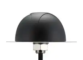
Illustrative purposes only

MA710.A.ABI.001
Combo Antenna, 2.6GHz to 3.5GHz, 2.5 VSWR, 3.2dBi Gain, 50ohm, Vertical Polarisation, Screw
⚠️ Reference pricing provided. In case of supply shortages, we will connect you with our trusted procurement partners to ensure your project's continuity.
- Manufacturer: TAOGLAS
- Product type:
- Antenna Type:Combo; Frequency Min:2.6GHz; Frequency Max:3.5GHz; Antenna Mounting:Screw; Gain:3.2dBi; VSWR:2.5; Input Power:-; Input Impedance:50ohm; Antenna Polarisation:Vertical; Produ
- Gain: 3.2dBi
- SVHC: To Be Advised
- VSWR: 2.5
- Input Power: -
- Antenna Type: Combo
- Frequency Max: 3.5GHz
- Frequency Min: 2.6GHz
- Product Range: Pantheon
- Input Impedance: 50ohm
- Antenna Mounting: Screw
- Antenna Polarisation: Vertical
| Delivery and price | |
|---|---|
| Units per pack | 50 |
| Price | 153.71 € |
| Current stock | 10+ |
| Lead time | 30 days |
Datasheet

## **SPECIFICATION**
Part No. : **MA710.A.ABI.001**
Product Name : Pantheon Antenna 3in1 MA.710 Screw-Mount (Permanent Mount)
2 x 4G/3G/2G LTE MIMO Cellular Antenna 1 x GPS/GLONASS/GALILEO Antenna
Feature
: 2 x Cellular 2G/3G/4G Antennas (MIMO) LTE / HSPA / GSM / GPRS / CDMA / UMTS 698~960MHz / 1710~2170MHz / 2300~2700MHz / 2900-3500MHz
1 x GPS/GLONASS/GALILEO 1575.42/1602MHz Active Antenna IP67 Waterproof
High Efficiency / Peak Gain Outdoor Antenna RoHS Compliant
SPE-13-8-073/D/SS Page 1 of 20
## **1. Introduction**
The MA710 Pantheon antenna is an omnidirectional heavy-duty, fully IP67 waterproof external M2M antenna for use in telematics, transportation and remote monitoring applications. It includes two LTE MIMO antennas and one GPS/GLONASS/GALILEO antenna, in the highest efficiency and peak gain possible. This antenna particularly finds its application in mobile video, vehicle communications, location and fleet management, safety & security, remote industrial equipment monitoring. The antenna consists of two LTE MIMO elements 698-960MHz, 1710-2170MHz, 2300~2700MHz, 2900-3500MHz. The antennas are designed to work equally well on LTE to deliver maximum data rates, or on legacy 3G and 2G frequencies where LTE is not available.
The GNSS antenna is a wide-band GPS/GLONASS/GALILEO element tuned to have optimum gain at 1575.42 MHz GPS/GALILEO and 1602MHz GLONASS frequencies.
Mechanically, we have packed 3 high efficiency and gain antennas in an extremely robust IP67 direct mount antenna package with excellent isolation (20dB+). The strengthened domed housing is designed to deflect tree branches and wires that tend to catch and break shark fin or rigid whip antennas. The Pantheon has its own internal ground-plane and can radiate on any mounting environment such as metal or plastic without affecting performance. The internal components are individually screwed down onto a robust plate, preventing damage from regular vehicle vibrations. A completely waterproof mounting seal prevents water from leaking under the housing.
The connectors and cable length are customizable. It is also available in White (MA710W).
SPE-13-8-073/D/SS Page 2 of 20
## **2. Specification Table**
|4G/3G/2G MIMO|4G/3G/2G MIMO|4G/3G/2G MIMO|4G/3G/2G MIMO|4G/3G/2G MIMO|4G/3G/2G MIMO|4G/3G/2G MIMO|4G/3G/2G MIMO|4G/3G/2G MIMO|4G/3G/2G MIMO|4G/3G/2G MIMO|4G/3G/2G MIMO|4G/3G/2G MIMO|4G/3G/2G MIMO|4G/3G/2G MIMO|4G/3G/2G MIMO|4G/3G/2G MIMO|4G/3G/2G MIMO|
|---|---|---|---|---|---|---|---|---|---|---|---|---|---|---|---|---|---|
||LTE|GSM<br>850||GSM<br>900||DCS||PCS|||WCDMA<br>I||ISM||LTE|||
|Frequency|698<br>~787|824<br>~896||880<br>~960||1710<br>~1880||1850<br>~1990|||1920<br>~2170||2400<br>~2500||2600~3500||MHz|
|MIMO 1||||||||||||||||||
|VSWR(max.)|2.5|2.5||3||2.5||2.5|||2.5||3||2.5|||
|Efficiency|66.17|51.88||47.87||39.97||47.67|||45.97||28.73||38.35||%|
|Peak Gain|2.52|1.48||1.15||1.03||1.22|||1.22||0.15||3.20||dBi|
|MIMO 2||||||||||||||||||
|VSWR(max.)|3.5|3.5||3.5||2.5||2.5|||2.5||2||2.5|||
|Efficiency|35.98|18.41||20.24||40.85||35.42|||37.68||42.27||35.24||%|
|Peak Gain|1.56|-2.08||-2.31||1.69||0.86|||2.06||2.99||2.97||dBi|
|Polarization|Vertical|||||||||||||||||
|Impedance|50||||||||||||||||Ω|
|GPS-GLONASS-GALILEO||||||||||||||||||
|Centre<br>Frequency|1575.42MHz / 1602MHz|||||||||||||||||
|Bandwidth|10MHz|||||||||||||||||
|Radiation<br>Efficiency|50 % (without cable)|||||||||||||||||
|Passive Gain<br>@Zenith|4.0 dBi typ. (with ψ=140mm ground)|||||||||||||||||
|VSWR|2|||||||||||||||||
|Impedance|50Ω|||||||||||||||||
|DC Power<br>Input Range|1.8V ~ 5V|||||||||||||||||
|DC input|**1.8V**||||**3.3V**||||**4.0V**|||||**5.5V**||||
|MHz|**1575.42**||**1602**||**1575.42**||**1602**||**1575.42**|||**1602**||**1575.42**||**1602**||
|VSWR|2||2||2||2||2|||2||2||2||
|LNA Gain|17||17||29.2||29||31|||31||32.3||32||
|Noise Figure|3.4||3.4||3.1||3.1||3.2|||3.2||3.4||3.4||
|Power<br>Consumption|3.2||3.2||7.5||7.5||9.4|||9.4||15||15||
|Band<br>Attenuation|1535MHz: -20dB<br>1642MHz: -20dB|||||1520MHz: -20dB<br>1642MHz: -20dB||||1520MHz: -20dB<br>1642MHz: -20dB||||1520MHz: -20dB<br>1642MHz: -20dB||||
|Cable|3m RG174 standard|||||||||||||||||
|Connector|SMA(M)standard|||||||||||||||||
SPE-13-8-073/D/SS Page 3 of 20
|Antenna Dimensions|Height 85.7mm x Diameter 145.6mm|
|---|---|
|Casing|Wonderloy PC-540 PC/ABS Alloy|
|Waterproof|IP67|
|4G/3G/2G MIMO 1|3M Low Loss CFD-200 SMA(M)|
|4G/3G/2G MIMO 2|3M Low Loss CFD-200 SMA(M)|
|GPS/GLONASS/GALILEO|3M RG-174 SMA(M)|
|ENVIRONMENTAL||
|Operation Temperature|-40°C to 85°C|
|Storage Temperature|-40°C to 90°C|
|Humidity|Non-condensing65°C 95% RH|
- all measurements were conducted with 3m low loss CFD200 cable on cellular and RG-174 cable on GPS/GLONASS/GALILEO
SPE-13-8-073/D/SS Page 4 of 20
|LTE BANDS|LTE BANDS|LTE BANDS|LTE BANDS|LTE BANDS|
|---|---|---|---|---|
|Band Number<br>~~a~~|LTE/LTE-Advanced/WCDMA/HSPA/HSPA+/TD-SCDMA||||
||**Uplink**|**Downlink**|**MIMO 1**|**MIMO 2**|
|**1**|UL: 1920 to 1980|DL: 2110 to 2170|✓|✓|
|**2**|UL: 1850 to 1910|DL: 1930 to 1990|✓|✓|
|**3**|UL: 1710 to 1785|DL: 1805 to 1880|✓|✓|
|**4**|UL: 1710 to 1755|DL: 2110 to 2155|✓|✓|
|**5**|UL: 824 to 849|DL: 869 to 894|✓||
|**7**|UL: 2500 to 2570|DL:2620 to 2690|✓|✓|
|**8**|UL: 880 to 915|DL: 925 to 960|✓||
|**9**|UL: 1749.9 to 1784.9|DL: 1844.9 to 1879.9|✓|✓|
|**11**|UL: 1427.9 to 1447.9|DL: 1475.9 to 1495.9|||
|**12**|UL: 699 to 716|DL: 729 to 746|✓|✓|
|**13**|UL: 777 to 787|DL: 746 to 756|✓|✓|
|**14**|UL: 788 to 798|DL: 758 to 768|✓|✓|
|**17**|UL: 704 to 716|DL: 734 to 746 (LTE only)|✓|✓|
|**18**|UL: 815 to 830|DL: 860 to 875 (LET only)|✓||
|**19**|UL: 830 to 845|DL: 875 to 890|✓||
|**20**|UL: 832 to 862|DL: 791 to 821|✓||
|**21**|UL: 1447.9 to 1462.9|DL: 1495.9 to 1510.9|||
|**22**|UL: 3410 to 3490|DL: 3510 to 3590|||
|**23**|UL:2000 to 2020|DL: 2180 to 2200 (LTE only)|✓|✓|
|**24**|UL:1625.5 to 1660.5|DL: 1525 to 1559 (LTE only)|✓|✓|
|**25**|UL: 1850 to 1915|DL: 1930 to 1995|✓|✓|
|**26**|UL: 814 to 849|DL: 859 to 894|✓||
|**27**|UL: 807 to 824|DL: 852 to 869 (LTE only)|✓||
|**28**|UL: 703 to 748|DL: 758 to 803 (LTE only)|✓||
|**29**|UL: -|DL: 717 to 728 (LTE only)|✓|✓|
|**30**|UL: 2305 to 2315|DL: 2350 to 2360 (LTE only)|✓|✓|
|**31**|UL: 452.5 to 457.5|DL: 462.5 to 467.5 (LTE only)|||
|**32**|UL: -|DL: 1452 - 1496|||
|**35**|1850 to 1910||✓|✓|
|**38**|2570 to 2620||✓|✓|
|**39**|1880 to 1920||✓|✓|
|**40**|2300 to 2400||✓|✓|
|**41**|2496 to 2690||✓|✓|
|**42**|3400 to 3600||✓||
|**43**|3600 to 3800||||
*Covered bands represent an efficiency greater than 20%
SPE-13-8-073/D/SS Page 5 of 20
## **3. LTE MIMO**
## **3.1. LTE MIMO 1 and LTE MIMO 2 Specification**
## 3.1.1. Return Loss
|LTE MIMO 1|LTE MIMO 1|
|---|---|
|LTE MIMO 2|LTE MIMO 2|
## 3.1.2. Maximum Gain
|LTE MIMO 1|LTE MIMO 1|
|---|---|
|LTE MIMO 2|LTE MIMO 2|
SPE-13-8-073/D/SS Page 6 of 20
## 3.1.3. Average Gain
——LTE LTE MIMO 1 Main LTE MIMO 2 Diversity —LTE
## 3.1.4. Efficiency
**==> picture [72 x 64] intentionally omitted <==**
**----- Start of picture text -----**<br>
LTE MIMO 1<br>LTE MIMO 2<br>**----- End of picture text -----**<br>
SPE-13-8-073/D/SS Page 7 of 20
## **3.2. Radiation Patterns**
**==> picture [112 x 56] intentionally omitted <==**
**----- Start of picture text -----**<br>
Y<br>Z X<br>**----- End of picture text -----**<br>
SPE-13-8-073/D/SS Page 8 of 20
## 3.2.1. 3.2.1 LTE MIMO 1 Radiation Pattern
XY plane
**==> picture [380 x 349] intentionally omitted <==**
**----- Start of picture text -----**<br>
X X<br>0 0<br>——__ 49 ———__<br>30 330 30<br>—— ;<br>So oS<br>60 300 / 60<br>/ S 20-—-—L<br>— | [—~ 30<br>Y Y<br>} | 90 270 | {1 | -4o i | | 199<br>Y —~ 704M 2 N a<br>120 ozs 4mHe 240. / | \ yy, 7 120<br>nt —824MHz —— —<br>150 —880MHz 210 150 ~~<br>180 —960MHz 180<br>(dBi) (dBi)<br>X X<br>0 0<br>——__ 49<br>30 330 30<br>o—_<br>NSS 60 300 . L- su0 — S\~\ \ 60<br>N .20.—-~<br>| | tf 23054 |<br>Y Y<br>**----- End of picture text -----**<br>
SPE-13-8-073/D/SS Page 9 of 20
## XZ Plane
**==> picture [379 x 350] intentionally omitted <==**
**----- Start of picture text -----**<br>
Z Z<br>0 0<br>10<br>30 330 \ 30<br>[ Q :<br>= ( \ = =<br>X<br>60 300 i \ \ 60<br>\) \205 .<br>Y 90 X 270 40 } 90 X<br>~x >,<br>—751MHz . y<br>py 120 240 Sy Y 120<br>—824MHz Ss . —<br>\ 150 — 880MHz 210 / \ "450 ——<br>—960MH<br>api z 180 api)<br>Z Z<br>0 0<br>10<br>30 330 \ | 30<br>cle \o y<br>| ™ \ Ay<br>I~ \ 60 300 , / 60<br>a) a _ “3204 ——<br>X X<br>**----- End of picture text -----**<br>
SPE-13-8-073/D/SS Page 10 of 20
## 3.2.2. LTE MIMO 2 Radiation Pattern
## XY Plane
## **X**
**==> picture [114 x 250] intentionally omitted <==**
**----- Start of picture text -----**<br>
Y<br>—_ ) 90<br>T 4p<br>| \ / 7 120<br>YY<br>150<br>180<br>(dBi)<br>X<br>0<br>30<br>60<br>|<br>Y<br>**----- End of picture text -----**<br>
**==> picture [14 x 10] intentionally omitted <==**
**----- Start of picture text -----**<br>
X<br>**----- End of picture text -----**<br>
**==> picture [114 x 251] intentionally omitted <==**
**----- Start of picture text -----**<br>
Y<br>a | 90<br>Wy<br>120<br>/<br>| 150 ~~<br>180<br>(dBi)<br>X<br>0<br>30<br>——<br>60<br>r |<br>Y<br>**----- End of picture text -----**<br>
SPE-13-8-073/D/SS Page 11 of 20
## XZ Plane
**==> picture [379 x 349] intentionally omitted <==**
**----- Start of picture text -----**<br>
Z Z<br>0 0<br>10<br>] 30 330 \ 30<br>; Ty . =iad ssf ~ ;<br>60 300 Za aN sp<br>\\ b P20. \<br>X X<br>— A 50 _ NN | 7<br>AZ / 409. 7S MHz 240 NES 7. A 4190<br>—824MHz 7 \<br>\ 60 —880MHz 210 / \ “450<br>180 (dBi) — 960MH2 180 ei<br>Z Z<br>0 0<br>10<br>30 330 \ 30<br>/ e— y<br>60 300 / ve’ 60<br>\ — e804MWK \20, \No<br>X X<br>**----- End of picture text -----**<br>
SPE-13-8-073/D/SS Page 12 of 20
## **4. GPS/GLONASS/GALILEO**
## **4.1. Block diagram**
## **4.2. Return Loss**
SPE-13-8-073/D/SS Page 13 of 20
## **4.3. Radiation pattern**
XZ Plane Free Space @1575.42MHz
SPE-13-8-073/D/SS Page 14 of 20
YZ Plane Free Space @1575.42MHz
XZ Plane Free Space @1602MHz
SPE-13-8-073/D/SS Page 15 of 20
## YZ Plane Free Space @1602MHz
SPE-13-8-073/D/SS Page 16 of 20
## **4.4 GPS/GLONASS/GALILEO LNA**
SPE-13-8-073/D/SS Page 17 of 20
## **5. Mechanical Drawing (Unit: mm)**
SPE-13-8-073/D/SS Page 18 of 20
## **6. Packaging**
SPE-13-8-073/D/SS Page 19 of 20
Taoglas makes no warranties based on the accuracy or completeness of the contents of this document and reserves the right to make changes to specifications and product descriptions at any time without notice. Taoglas reserves all rights to this document and the information contained herein.
Reproduction, use or disclosure to third parties without express permission is strictly prohibited.
Copyright © Taoglas Ltd.
SPE-13-8-073/D/SS Page 20 of 20
Updated at June 9, 2026
About Novapart
Novapart is a B2B electronic component broker specialising in stock shortages and cost reduction. We source hard-to-find parts and identify compliant alternatives across a catalogue of 410,000+ components from 500+ manufacturers.
Learn more →Stock Shortage Specialist
When a component is unavailable, discontinued or has an unacceptable lead time, we tap into our network of vetted European and Asian distributors to source what you need — without compromising on quality or traceability.
Request a quote →Compliant Alternatives
We identify pin-to-pin, electrically equivalent substitutes that meet the same certifications (RoHS, AEC-Q100, REACH) as your original specification — validated against datasheets, not just part numbers. Often at a lower cost.
BOM Analysis service →