
Image not available
Illustrative purposes only

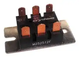
M252512F
THYRISTOR DIODE MODULE, 600V, 25A
⚠️ Reference pricing provided. In case of supply shortages, we will connect you with our trusted procurement partners to ensure your project's continuity.
- Manufacturer: SENSATA/CRYDOM
- Product type: Thyristors - SCR Modules
- SCR Module Type:Bridge Rectifier, Single Phase - SCR / Diode; Peak Repetitive Off State Voltage:600V; Gate Trigger Current Max:50mA; Average Forward Current:25A; On 73M3260
- SVHC: No SVHC (12-Jan-2017)
- No. of Pins: 6Pins
- Product Range: M25 Series
- SCR Module Type: Bridge Rectifier, Single Phase - SCR / Diode
- Thyristor Mounting: Panel
- On State RMS Current: -
- Thyristor Case Style: Module
- Average Forward Current: 25A
- Gate Trigger Current Max: 50mA
- Gate Trigger Voltage Max: 2.5V
- Operating Temperature Max: 125°C
- Repetitive Peak Reverse Voltage: 600V
- Peak Repetitive Off State Voltage: 600V
| Delivery and price | |
|---|---|
| Units per pack | 1 |
| Price | 92.83 € |
| Current stock | 10+ |
| Lead time | 30 days |
Datasheet

/4er\ SILICON M25 SERIES Toe i 6) POWER 25A/40A POWER | jA<>4 CUBE SCR/DIODE MODULES [| FEATURES oe ak abe Eight standard circuit configurations available _ fe: en Ultra-High surge current cababilities 2 wa FO 2500VAC RMS terminal-to-base isolation 8 r £ 4g 2 ‘nal ba **r** ier avai _ — 2 og Insulated terminal barrier available, M25E case. . “ ae lna Utilizeshighly efficient SPC’s powerthermalhybridmanagement. technology for ga UL Component Recognition a Available in standard 120VAC, 240 VAC, | 320VAC, 440VAC and 480VAC ratings. a

a 7 aa i :: i | i | j : :

**==> picture [506 x 407] intentionally omitted <==**

**----- Start of picture text -----**<br>
PARAMETER = Sm. | UNITS |. SPECIFICATIONLIMITS |. =, ~GONDITIONS<br>(Ciouils 1.2.9 86)<br>D6 Output Current (Max) Po fA fs| 40 | Te = 85°C<br>One-Cycle Surge Current (Peak) 60Hz Sine Wave, Non-Repetitive (Fig. 6)<br>I*t for;  Fusing (Max.) it2 ASS; 370 | 0 60HzReapplied Voltage Sine Wave with Full<br>Rate-of-Rise of On-State . Max. Vorm, Peak On-State<br>CurrentRate-of-Rise(Max.of Off-State ue . CurrentExponential= 9 RiseX lo (Avg)to 80% Vorm,<br>300V for 120Vams (- 1)<br>aye Voam 600V for 240Vams (-2)<br>g voneg 7 Vanna 1000V for 440Vanas (4)<br>*4200V for 480Vams (-5)<br>—<br>lsolation Voltage (Min.) 2500 Any Terminal-to-Base<br>Thermal Resistance (Case-to-Sink) With Thermal Grease<br>hermal Resistance Rc | °C/W 1.15 0.75 Per Device<br>(Junction-to-Case)<br>Reverse Gate Voltage (Peak)<br>Gate Current Required to Fire , A<br>all Devices (Max ) Sr m 80<br>Gate Voltage Required to Fire aro<br>DM<br>Case Style M25 or M25E See following page for circuit<br>configurations and outline dimensions<br>**----- End of picture text -----**<br>


* Higher vatues are available. Consult Factory.

34

» (@AA ;: | ti i

**==> picture [520 x 99] intentionally omitted <==**

**----- Start of picture text -----**<br>
PART NUNIBER DESIGNATION CODE<br>ivi25 40 3 2 FV<br>M25 OR M25E (INSULATED TERMINAL BARRIER) y . LONE NEE ELNG ODE<br>:2 [(] CASE STYLE _| | [ -<br>DC OUTPUT CURRENT FV - BOTH<br>25 OR 40A (M25 or M25E CASE) *VOLTS AC (RMS)<br>1-120V 4-440V<br>2-240V 5-480V<br>CIRCUIT DESIGNATION 3-320V * Consult Factory for higher voltages<br>**----- End of picture text -----**<br>


## M25/M25E CIRCUIT CONFIGURATIONS

## (See page 50 for characteristic curves)

**==> picture [540 x 583] intentionally omitted <==**

**----- Start of picture text -----**<br>
COMMONHYBRIDCATHODEBRIDGE SCRS CIRCUIT 1 AC)aam a A| VOLTAGEFREE WHEELING SUPPRESSOR Aci G1 =<br>AG? a DIODE Ace G2 +<br>Aci LW a<br>rt Gr DIODE ace G2 +<br>ink AC2 G2 =~<br>FULL SCR oe<br>BRIDGE CIRCUIT 3 Acacan = ee, . VOLTAGE SUPPRESSOR Aci—G1 G30Giob<br>& Ati G2 AG<br>AC SWITCH CIRCUIT 4 Gt VOLTAGE SUPPRESSOR<br>ACY AG?<br>» ge x GOT<br>(@AA DOUBLERSch CIRCUITS ro]lay eo<br>HYBRIDQR BRIDGE arTy AL Of + a7~<br>DOUBLER CIRCUIT 6 a e — VOLTAGE SUPPRESSOR<br>AC2 _ 4 ACZ G2 ca<br>Pa ==<br>SCR CENTER TAP faa Ac) 1<br>COMMON CATHODE CIRCUIT] kw M2 G2 +<br>ACZ eS,<br>DOUBLERHYBRID CIRCUIT 8 ” G2a ok<br>_<br>M25 /M2S5E OUTLINE/MOUNTING DIMENSIONS<br>|<br>M25 CASE DIMENSIONS M25E CASE DIMENSIONS Case M2SE, which features an insulated ler-<br>t minal barrier, can be substituted for case M25 as<br>| [_ INCHES tI | all alactrical specifications are identical.<br>i 3 esfentcoeyS fom | = ee<br>>)<br>PO | = cates a | A | 2510 | 2490 FL [Se ea == | Ll | A__| 2.510<br>i Ne seteLicence ritLU | c__{a | os10-|0.860 | 0. 4086 0 21.80 ~PJALIEKSL. es\[= [=>] pot | § | [re 0.880Poste<br>i jpeg | po | 1.265 | 1.245 | 31.90 | 31.66 — a 7 |p [|] [1.255] 31.90<br>' i h- 0.205 | 0.195 | 5.20 ne abe bs | | e€ | [0208][|][ o195] [|] [5.20]<br>; 7.010 | 0.940 | 25.60 | 23.90 $1, 1.010 | 0.940 | 25.60<br>7 ae ee v4.99 [1422 Le [080<br>ble 3 FASTONS 7.940 | 50.00 | 49.30 oe de 28 Hy 1,970 50.00<br>: 8 eni of? lal*| K— 1.930 | 1.900 48.20 cer [SRN] [uisaeiciere] [2.] [FASTONS] 1.930 49.00<br>p= ee ees 3067 | 0.087 ad Pe Sentey ee eae<br>: Tr MOUNTING TORQUE REQUIRED y nn a te<br>i (A) Mounting Screws..............20 in-lb. int= et : | _m | 0052 | oova | ta2) 1.22<br>i ql MOUNTING TORQUE REQUIRED<br>5 Mounting Screws................20 Inst.<br>i<br>i<br>:<br>i<br>**----- End of picture text -----**<br>


**==> picture [6 x 19] intentionally omitted <==**

**----- Start of picture text -----**<br>
L<br>**----- End of picture text -----**<br>


35

**==> picture [315 x 9] intentionally omitted <==**

**----- Start of picture text -----**<br>
N25 CHARACTERISTIC CURVES (See page 46 & 47 for product data)<br>**----- End of picture text -----**<br>


**==> picture [557 x 665] intentionally omitted <==**

**----- Start of picture text -----**<br>
PPSARGE<br>E40 ys iE: | *<br>: DONGP aK 82 we =eee100 Y, mS NEReg Ft |i<br>— NON 2 002COG ANN 45 :<br>rr I N 104 2s fe 20 y No N 97 sO a<br>é |i | eS ne 4s<br>%9 40 20 30 40 500 25 50 75 100 125 °9 40 20 30 40 500 25 50 75 100 125<br>LOAD CURRENT AMBIENT TEMP. (°C) LOAD CURRENT AMBIENT TEMP. (°C) |<br>FIGURE1 — THERMAL DERATING CURVES, M2540 FIGURE2 — THERMAL DERATING CURVES, M2540 :<br>CIRCUITS 4,5,7 & 8 CIRCUITS 1,2,3 &6 i<br>PPAR:<br>= [25] \ a9 S44g |= FREER:50 i x ag aeg |:<br>wn \ i<br>b, a £5 o Z = Oo<br>eo Ne ee ee Ae NN ee |<br>. ac5 10 | TANSDN | Wes acPLA20  LANAsae NO 2s !<br>a oO5 5S 10 15 (20 250SERN«25 50 75iN100 125 WS &® 10oSALTFZ 10 15 20250 LILE25 |50i ON75ESN100 125Ww<br>LOAD CURRENT AMBIENT TEMP. (°C) LOAD CURRENT AMBIENT TEMP. (°C)<br>FIGURE 3 ~ THERMAL DERATING CURVES, M2525 FIGURE 4 — THERMAL DERATING CURVES, M2525<br>CIRCUITS 45,7 &8 CIRCUITS 1,2,3 & 6 e<br>=z ° a lll A Krowing maximum output current and maximum ambient<br>. use derati determi ired heat<br>c an power issipation curve, locate ne pain correspon ing<br>zt corresponding to maximum ambient temperature. From heat<br>3 (EI Extendthe line farther lo the right and read on the right hand<br>D a ll scale the maximum allowable base plate temperature.<br><= of1 eeLt | i<br>So Eeerci<br>. | HCH<br>aniiinn H A<br>PEAK CURRENT (AMPS) “me<br>FIGURE 5 — FORWARD VOLTAGE DROP VS.<br>PEAK CURRENT (@ 125°C)<br>| oo w [vetw]<br>< | | | |<br> @ EI -HAG 5." PR ILL<br>oe ee || HH 22 | _\\ —<br>zee ee ma |Ne<br>Se og wa AE z% °NR<br>So Fepbeo T TETT| Zz 4 DN<br>oe a | oe<br>eSo |_| [esaPE s * Jaw garetnicces [y= 7<br>1a 10 100 1000 9 0tS0.5 1.0 1.5 2.0 2.5 3.0 3.5 @)oe<br>NUMBER OF CYCLES AT 60 Hz Ig INSTANTANEOUS GATE CURRENT (AMPS)<br>FIGURE 6 ~ MAXIMUM NON-REPETITIVE SURGE FIGURE 7 — GATE CHARACTERISTICS<br>**----- End of picture text -----**<br>


**==> picture [163 x 15] intentionally omitted <==**

**----- Start of picture text -----**<br>
FIGURE 6 ~ MAXIMUM NON-REPETITIVE SURGE<br>CURRENT VS. DURATION<br>**----- End of picture text -----**<br>


aR
Updated at June 7, 2026
About Novapart
Novapart is a B2B electronic component broker specialising in stock shortages and cost reduction. We source hard-to-find parts and identify compliant alternatives across a catalogue of 410,000+ components from 500+ manufacturers.
Learn more →Stock Shortage Specialist
When a component is unavailable, discontinued or has an unacceptable lead time, we tap into our network of vetted European and Asian distributors to source what you need — without compromising on quality or traceability.
Request a quote →Compliant Alternatives
We identify pin-to-pin, electrically equivalent substitutes that meet the same certifications (RoHS, AEC-Q100, REACH) as your original specification — validated against datasheets, not just part numbers. Often at a lower cost.
BOM Analysis service →