
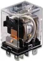


LY2-8 DC48
General Purpose Relay, LY Series, Power, Non Latching, DPDT, 48 VDC, 15 A
- Manufacturer: OMRON INDUSTRIAL AUTOMATION
- Product type: Power Relays
- Contact Configuration:DPDT; Coil Voltage:48VDC; Contact Current:15A; Product Range:LY Series; Relay Mounting:Socket; Coil Type:Non Latching; Contact Voltage VAC:120VAC; Relay Terminals:So
- SVHC: No SVHC (17-Dec-2014)
- Coil Type: Non Latching
- Coil Voltage: 48VDC
- Product Range: LY Series
- Relay Mounting: Socket
- Coil Resistance: 2.6kohm
- Contact Current: 10A
- Relay Terminals: Quick Connect
- Contact Material: Silver Alloy
- Contact Voltage VAC: 120VAC
- Contact Voltage VDC: 28VDC
- Approvals & Standards: CE, CSA, UL, VDE
- Contact Configuration: DPDT
| Delivery and price | |
|---|---|
| Units per pack | 50 |
| Price | 14.02 € |
| Current stock | 10+ |
| Lead time | 30 days |
## **General Purpose Relay LY**

- Arc barrier equipped.

- High dielectric strength (2,000 VAC).

- Long dependable service life assured by Ag-Alloy contacts.

- Choose models with single or  bifurcated contacts, LED indicator, diode surge suppression, push-to-test button, or RC circuit.

- UL, CSA, and TUV approvals on all standard  LY Relays.

- CE marks included on non-PCB mount versions.

## **Orderin Information g**

To Order: Select the part number and add the desired coil voltage rating (e.g., LY1- _DC6_ ).

|**Type**|**Terminal**|**Contact**<br>**form**<br>~~Cn~~|**Model**<br>~~Cn~~|**Model**<br>~~Cn~~|**Model**<br>~~Cn~~|**Model**<br>~~Cn~~|
|---|---|---|---|---|---|---|
||||**Single contact**<br>~~Cn~~||**Bifurcated contact**||
||||**Standard**<br>**bracket**<br>**mounting**|**Upper**<br>**mounting**<br>**bracket**|**Standard**<br>**bracket**<br>**mounting**|**Upper**<br>**mounting**<br>**bracket**|
|Standard|Plug-in/solder|SPDT<br>~~a~~<br>~~es~~|**LY1**<br>~~Qf~~|**LY1F**<br>~~Qf~~|**—**<br>~~Qf~~|**—**<br>~~Qf~~|
|||DPDT<br>~~es~~<br>~~es~~|**LY2**<br>~~Qf~~<br>~~Qf~~|**LY2F**<br>~~Qf~~<br>~~Qf~~|**LY2Z**<br>~~Qf~~<br>~~Qf~~|**LY2ZF**<br>~~Qf~~<br>~~Qf~~|
|||3PDT<br>~~es~~<br>~~es~~<br>~~Rs~~|**LY3**<br>~~Qf~~<br>~~Qf~~<br>~~GG~~|**LY3F**<br>~~Qf~~<br>~~Qf~~<br>~~GG~~|**—**<br>~~Qf~~<br>~~Qf~~<br>~~GG~~|**—**<br>~~Qf~~<br>~~Qf~~<br>~~GG~~|
|||4PDT<br>~~es~~<br>~~Rs~~<br>~~Rs~~|**LY4**<br>~~Qf~~<br>~~GG~~<br>~~GG~~|**LY4F**<br>~~Qf~~<br>~~GG~~<br>~~GG~~|**—**<br>~~Qf~~<br>~~GG~~<br>~~GG~~|**—**<br>~~Qf~~<br>~~GG~~<br>~~GG~~|
||PCB|SPDT<br>~~Rs~~<br>~~Rs~~<br>~~es~~|**LY1-0**<br>~~GG~~<br>~~GG~~<br>~~Qf~~|**—**<br>~~GG~~<br>~~GG~~<br>~~Qf~~|**—**<br>~~GG~~<br>~~GG~~<br>~~Qf~~|**—**<br>~~GG~~<br>~~GG~~<br>~~Qf~~|
|||DPDT<br>~~Rs~~<br>~~es~~<br>~~es~~|**LY2-0**<br>~~GG~~<br>~~Qf~~<br>~~Qf~~|**—**<br>~~GG~~<br>~~Qf~~<br>~~Qf~~|**LY2Z-0**<br>~~GG~~<br>~~Qf~~<br>~~Qf~~|**—**<br>~~GG~~<br>~~Qf~~<br>~~Qf~~|
|||3PDT<br>~~es~~<br>~~es~~<br>~~Rs~~|**LY3-0**<br>~~Qf~~<br>~~Qf~~<br>~~GG~~|**—**<br>~~Qf~~<br>~~Qf~~<br>~~GG~~|**—**<br>~~Qf~~<br>~~Qf~~<br>~~GG~~|**—**<br>~~Qf~~<br>~~Qf~~<br>~~GG~~|
|||4PDT<br>~~es~~<br>~~Rs~~<br>~~Rs~~|**LY4-0**<br>~~Qf~~<br>~~GG~~<br>~~GG~~|**—**<br>~~Qf~~<br>~~GG~~<br>~~GG~~|**—**<br>~~Qf~~<br>~~GG~~<br>~~GG~~|**—**<br>~~Qf~~<br>~~GG~~<br>~~GG~~|
|LED indicator|Plug-in/solder|SPDT<br>~~Rs~~<br>~~Rs~~<br>~~es~~|**LY1N**<br>~~GG~~<br>~~GG~~<br>~~Qf~~|**—**<br>~~GG~~<br>~~GG~~<br>~~Qf~~|**—**<br>~~GG~~<br>~~GG~~<br>~~Qf~~|**—**<br>~~GG~~<br>~~GG~~<br>~~Qf~~|
|||DPDT<br>~~Rs~~<br>~~es~~<br>~~es~~|**LY2N**<br>~~GG~~<br>~~Qf~~<br>~~Qf~~|**—**<br>~~GG~~<br>~~Qf~~<br>~~Qf~~|**LY2ZN**<br>~~GG~~<br>~~Qf~~<br>~~Qf~~|**—**<br>~~GG~~<br>~~Qf~~<br>~~Qf~~|
|||3PDT<br>~~es~~<br>~~es~~<br>~~es~~|**LY3N**<br>~~Qf~~<br>~~Qf~~<br>~~Qf~~|**—**<br>~~Qf~~<br>~~Qf~~<br>~~Qf~~|**—**<br>~~Qf~~<br>~~Qf~~<br>~~Qf~~|**—**<br>~~Qf~~<br>~~Qf~~<br>~~Qf~~|
|||4PDT<br>~~es~~<br>~~es~~<br>~~es~~|**LY4N**<br>~~Qf~~<br>~~Qf~~<br>~~Qf~~|**—**<br>~~Qf~~<br>~~Qf~~<br>~~Qf~~|**—**<br>~~Qf~~<br>~~Qf~~<br>~~Qf~~|**—**<br>~~Qf~~<br>~~Qf~~<br>~~Qf~~|
|Diode surge<br>suppression||SPDT<br>~~es~~<br>~~es~~<br>~~es~~|**LY1-D**<br>~~Qf~~<br>~~Qf~~<br>~~Qf~~|**—**<br>~~Qf~~<br>~~Qf~~<br>~~Qf~~|**—**<br>~~Qf~~<br>~~Qf~~<br>~~Qf~~|**—**<br>~~Qf~~<br>~~Qf~~<br>~~Qf~~|
|||DPDT<br>~~es~~<br>~~es~~<br>~~es~~|**LY2-D**<br>~~Qf~~<br>~~Qf~~<br>~~Qf~~|**—**<br>~~Qf~~<br>~~Qf~~<br>~~Qf~~|**LY2Z-D**<br>~~Qf~~<br>~~Qf~~<br>~~Qf~~|**—**<br>~~Qf~~<br>~~Qf~~<br>~~Qf~~|
|||3PDT<br>~~es~~<br>~~es~~<br>~~es~~|**LY3-D**<br>~~Qf~~<br>~~Qf~~<br>~~Qf~~|**—**<br>~~Qf~~<br>~~Qf~~<br>~~Qf~~|**—**<br>~~Qf~~<br>~~Qf~~<br>~~Qf~~|**—**<br>~~Qf~~<br>~~Qf~~<br>~~Qf~~|
|||4PDT<br>~~es~~<br>~~es~~<br>~~es~~|**LY4-D**<br>~~Qf~~<br>~~Qf~~<br>~~Qf~~|**—**<br>~~Qf~~<br>~~Qf~~<br>~~Qf~~|**—**<br>~~Qf~~<br>~~Qf~~<br>~~Qf~~|**—**<br>~~Qf~~<br>~~Qf~~<br>~~Qf~~|
|LED indicator<br>and diode surge<br>suppression<br>~~P|~~||SPDT<br>~~es~~<br>~~es~~<br>~~es~~|**LY1N-D2**<br>~~Qf~~<br>~~Qf~~<br>~~Qf~~|**—**<br>~~Qf~~<br>~~Qf~~<br>~~Qf~~|**—**<br>~~Qf~~<br>~~Qf~~<br>~~Qf~~|**—**<br>~~Qf~~<br>~~Qf~~<br>~~Qf~~|
|||DPDT<br>~~es~~<br>~~es~~<br>~~es~~|**LY2N-D2**<br>~~Qf~~<br>~~Qf~~<br>~~Qf~~|**—**<br>~~Qf~~<br>~~Qf~~<br>~~Qf~~|**LY2ZN-D2**<br>~~Qf~~<br>~~Qf~~<br>~~Qf~~|**—**<br>~~Qf~~<br>~~Qf~~<br>~~Qf~~|
|||4PDT<br>~~es~~<br>~~es~~<br>~~es~~|**LY4N-D2**<br>~~Qf~~<br>~~Qf~~<br>~~Qf~~|**—**<br>~~Qf~~<br>~~Qf~~<br>~~Qf~~|**—**<br>~~Qf~~<br>~~Qf~~<br>~~Qf~~|**—**<br>~~Qf~~<br>~~Qf~~|
|RC circuit<br>~~P|~~<br>~~|~~||SPDT<br>~~es~~<br>~~es~~<br>~~es~~|**LY1-CR**<br>~~Qf~~<br>~~Qf~~<br>~~Qf~~|**—**<br>~~Qf~~<br>~~Qf~~<br>~~Qf~~|**—**<br>~~Qf~~<br>~~Qf~~<br>~~Qf~~|**—**<br>~~Qf~~<br>~~Qf~~|
|||DPDT<br>~~es~~<br>~~es~~<br>~~es~~<br>~~Se~~|**LY2-CR**<br>~~Qf~~<br>~~Qf~~<br>~~Qf~~|**—**<br>~~Qf~~<br>~~Qf~~<br>~~Qf~~|**LY2Z-CR**<br>~~Qf~~<br>~~Qf~~<br>~~Qf~~|**—**<br>~~Qf~~<br>~~Qf~~|
|LED indicator<br>and RC circuit<br>~~P|~~<br>~~|~~||SPDT<br>~~es~~<br>~~es~~<br>~~Se~~|**LY1N-CR**<br>~~Qf~~<br>~~Qf~~|**—**<br>~~Qf~~<br>~~Qf~~|**—**<br>~~Qf~~<br>~~Qf~~|**—**<br>~~Qf~~<br>~~Qf~~|
|||DPDT<br>~~es~~<br>~~Se~~<br>~~a~~|**LY2N-CR**<br>~~Qf~~|**—**<br>~~Qf~~|**LY2ZN-CR**<br>~~Qf~~|**—**<br>~~Qf~~|


- **Note: 1.** Types with specifications other than those listed are available. Contact your Omron Sales representative.

   **2.** To order connecting sockets and mounting tracks, see “Accessories” section.

   **3.** Relays with RC circuit are only available in AC coil voltages of 100 VAC or greater.

General Purpose Relay **LY** 307

|**Type**<br>~~—_—=——~~|**Terminal**<br>~~—_—=——~~|**Contact**<br>**form**<br>~~—_—=——~~|**Model**<br>~~—_—=——~~|**Model**<br>~~—_—=——~~|**Model**<br>~~—_—=——~~|**Model**<br>~~—_—=——~~|
|---|---|---|---|---|---|---|
||||**Single contact**<br>~~—_—=——~~||**Bifurcated contact**<br>~~—_—=——~~||
||||**Standard**<br>**bracket**<br>**mounting**<br>~~—_—=——~~|**Upper**<br>**mounting**<br>**bracket**<br>~~—_—=——~~|**Standard**<br>**bracket**<br>**mounting**<br>~~—_—=——~~|**Upper**<br>**mounting**<br>**bracket**<br>~~—_—=——~~|
|Push-to-test<br>button<br>~~—_—=——~~|Plug-in/solder<br>~~—_—=——~~|SPDT<br>~~—_—=——~~|**LY1l4**<br>~~—_—=——~~|**—**<br>~~—_—=——~~|**—**<br>~~—_—=——~~|**—**<br>~~—_—=——~~|
|||DPDT<br>~~—_—=——~~|**LY2l4**<br>~~—_—=——~~|**—**<br>~~—_—=——~~|**LY2Zl2**<br>~~—_—=——~~|**—**<br>~~—_—=——~~|
|||3PDT<br>~~—_—=——~~|**LY3l4**<br>~~—_—=——~~|**—**<br>~~—_—=——~~|**—**<br>~~—_—=——~~|**—**<br>~~—_—=——~~|
|||4PDT<br>~~—_—=——~~|**LY4l4**<br>~~—_—=——~~|**—**<br>~~—_—=——~~|**—**<br>~~—_—=——~~|**—**<br>~~—_—=——~~|
|LED indicator and<br>push-to-test button<br>~~—_—=——~~|Plug-in/solder<br>~~—_—=——~~|DPDT<br>~~—_—=——~~|**LY2l4N**<br>~~—_—=——~~|**—**<br>~~—_—=——~~|**LY2Zl2N**<br>~~—_—=——~~|**—**<br>~~—_—=——~~|
|||4PDT<br>~~—_—=——~~|**LY4l4N**<br>~~—_—=——~~|**—**<br>~~—_—=——~~|**—**<br>~~—_—=——~~|**—**<br>~~—_—=——~~|


## ■ **Accessories**

## **Connecting Sockets**

To Order: Select the appropriate part numbers for sockets, clips, and mounting tracks (if required) from the following charts.

**Track Mounted Sockets Relay Socket* Relay hold-down clip Mounting track Standard RC circuit** SPDT **PTF08A-E PYC-A1 Y92H-3 PFP-100N/PFP-50N** & DPDT **PFP-M** or **PFP-100N2** 3PDT **PTF11A PFP-S** (Option spacer) 4PDT **PTF14A-E** ~~==~~ * Track mounted socket can be used as a front connecting socket. **Back Connecting Sockets Relay Solder Wire wrap Relay hold-down clip Socket Mounting Plate terminal terminal socket socket Standard Push-to-test RC circuit Mtg. plate 1 10 12 18** SPDT **PT08 PT08QN PYC-P PYC-P2 PYC-1 PYC-S PYP-1 – – PYP-18** DPDT 3PDT **PT11 PT11QN PTP-1-3 – PTP-12 –** 4PDT **PT14 PT14QN PTP-1 PTP-10 – –** ~~ann====~~ **Note:** Types PYP-18, PTP-12 and PTP-10 may be cut to any desired length. ~~===~~ **Relay PC terminal socket Relay hold-down clip Standard Push-to-test RC circuit** SPDT **PT08-0 PYC-P PYC-P2 PYC-1** DPDT 3PDT **PT11-0** 4PDT **PT14-0** ~~[——~~

General Purpose Relay **LY**

308

## **S ecifications p**

## ■ **Contact Data**

|**Load**|**Single contact**|**Single contact**|**Single contact**|**Single contact**|**Bifurcated contact**|**Bifurcated contact**|
|---|---|---|---|---|---|---|
||**SPDT**||**DPDT, 3PDT, 4PDT**||**DPDT**||
||**Resistive load**<br>**(p.f. = 1)**|**Inductive load**<br>**(p.f. = 0.4)**<br>**(L/R = 7 ms)**|**Resistive load**<br>**(p.f. = 1)**|**Inductive load**<br>**(p.f. = 0.4)**<br>**(L/R = 7 ms)**|**Resistive load**<br>**(p.f. = 1)**|**Inductive load**<br>**(p.f. = 0.4)**<br>**(L/R = 7 ms)**|
|**Rated load**|15 A at 110 VAC<br>15 A at 24 VDC|10 A at 110 VAC<br>7 A at 24 VDC|10 A at 110 VAC<br>10 A at 24 VDC|7.5 A at 110 VAC<br>5 A at 24 VDC|5 A at 110 VAC<br>5 A at 24 VDC|4 A at 110 VAC<br>4 A at 24 VDC|
|**Contact material**|Ag-Alloy||||||
|**Carry current**|15 A||10 A||7 A||
|**Max. operating**<br>**voltage**|250 VAC<br>125 VDC||||||
|**Max. operating**<br>**current**|15 A||10 A||7 A||
|**Max. switching**<br>**capacity**|1,700 VA<br>360 W|1,100 VA<br>170 W|1,100 VA<br>240 W|825 VA<br>120 W|550 VA<br>120 W|440 VA<br>100 W|
|**Min. permissible**<br>**load**|100 mA, 5 VDC||||10 mA, 5 VDC||


## ■ **Coil Data**

## **1- and 2-pole Types – AC**

|**1- and 2-pole Types – AC- and 2-pole Types – AC and 2-pole Types – AC-pole Types – ACpole Types – AC– AC AC**|**1- and 2-pole Types – AC- and 2-pole Types – AC and 2-pole Types – AC-pole Types – ACpole Types – AC– AC AC**||||||||
|---|---|---|---|---|---|---|---|---|
|**Rated**<br>**Rated current (mA)**||**Coil**|**Coil inductance**|**Pick-up**||**Dropout**|**Maximum**|**Power**|
|**voltage (V)**|**voltage (V)**|**resistance**|**(ref. value) (H)**|**voltage**||**voltage**|**voltage**|**consumption**|
||**50 Hz**<br>**60 Hz**|**(**Ω**)**|**Armature**<br>**Armature**|**(% of rated voltage)**|**(% of rated voltage)**|||**(VA, W)**|
||||**OFF**<br>**ON**||||||
|6|214.10<br>183|12.20|0.04<br>0.08|80% max.||30% min.|110%|Approx.|
|12<br>24|106.50<br>91<br>53.80<br>46|46<br>180|0.17<br>0.33<br>0.69<br>1.30|||||1.00 to 1.20<br>(60 Hz)|
|50|25.70<br>22|788|3.22<br>5.66||||||
|100/110|11.70/12.90<br>10/11|3,750|14.54<br>24.60|||||Approx.|
|110/120<br>200/220|9.90/10.80<br>8.40/9.20<br>6.20/6.80<br>5.30/5.80|4,430<br>12,950|19.20<br>32.10<br>54.75<br>94.07|||||0.90 to 1.10<br>(60 Hz)|
|220/240|4.80/5.30<br>4.20/4.60|18,790|83.50<br>136.40||||||
|**1- and 2-pole Types– DC**|||||||||
|**Rated**<br>**voltage (V)**<br>**Rated current (mA)**<br>**Coil**<br>**resistance**<br>**(**Ω**)**<br>**Coil inductance**<br>**(ref. value) (H)**<br>**Pick-up**<br>**voltage**<br>**Dropout**<br>**voltage**<br>**Maximum**<br>**voltage**<br>**Power**<br>**consumption**<br>**(VA, W)**<br>**Armature**<br>**OFF**<br>**Armature**<br>**ON**<br>**(% of rated voltage)**<br>6<br>150<br>40<br>0.16<br>0.33<br>80% max.<br>10% min.<br>110%<br>Approx.<br>0.90<br>12<br>75<br>160<br>0.73<br>1.37<br>24<br>36.90<br>650<br>3.20<br>5.72<br>48<br>18.50<br>2,600<br>10.60<br>21<br>100/110<br>9.10/10<br>11,000<br>45.60<br>86.20<br>~~=.~~|||||||||
|**Note: 1.**|The rated current and coil resistance are measured at a coil temperature of 23°C (73°F) with tolerances of +15%, -20% for AC rated|||The rated current and coil resistance are measured at a coil temperature of 23°C (73°F) with tolerances of +15%, -20% for AC rated|The rated current and coil resistance are measured at a coil temperature of 23°C (73°F) with tolerances of +15%, -20% for AC rated||||
||current, and ±15% for DC rated coil resistance.||||||||
|**2.**|The AC coil resistance and inductance are reference values at 60 Hz.||||||||


**3.** The performance characteristics are measured at a coil temperature of 23°C (73°F).

**4.** Class B coil insulation is available.

General Purpose Relay **LY** 309

## **- – 3 pole Type AC**

|**Rated**<br>**voltage (V)**|**Rated current (mA)**|**Rated current (mA)**|**Coil**<br>**resistance**<br>**(**Ω**)**|**Coil inductance**<br>**(ref. value) (H)**|**Coil inductance**<br>**(ref. value) (H)**|**Pick-up**<br>**voltage**|**Dropout**<br>**voltage**|**Maximum**<br>**voltage**|**Power**<br>**consumption**<br>**(VA, W)**|
|---|---|---|---|---|---|---|---|---|---|
||**50 Hz**|**60 Hz**||**Armature**<br>**OFF**|**Armature**<br>**ON**|**(% of rated voltage)**||||
|6|310|270|6.70|0.03|0.05|80% max.|30% min.|110%|Approx.<br>1.60 to 2.00<br>(60 Hz)|
|12|159|134|24|0.12|0.21|||||
|24|80|67|100|0.44|0.79|||||
|50|38|33|410|2.24|3.87|||||
|100/110|15.90/18.30|13.60/15.60|2,300|10.50|18.50|||||
|120|17.30|14.8|2,450|11.50|20.60|||||
|200/220|10.50/11.60|9.00/9.90|8,650|34.80|59.50|||||
|240|9.40|8|10,400|38.60|74.60|||||


## **- – 3 pole Type DC**

|**Rated**<br>**voltage**<br>**(V)**|**Rated current (mA)**|**Coil**<br>**resistance**<br>**(**Ω**)**|**Coil inductance**<br>**(ref. value) (H)**|**Coil inductance**<br>**(ref. value) (H)**|**Pick-up**<br>**voltage**|**Dropout**<br>**voltage**|**Maximum**<br>**voltage**|**Power**<br>**consumption**<br>**(VA, W)**|
|---|---|---|---|---|---|---|---|---|
||||**Armature**<br>**OFF**|**Armature**<br>**ON**|**(% of rated voltage)**||||
|6|234|25.70|0.11|0.21|80% max.|10% min.|110%|Approx.<br>1.40|
|12|112|107|0.45|0.98|||||
|24|58.60|410|1.89|3.87|||||
|48|28.20|1,700|8.53|13.90|||||
|100/110|12.70/13|8,500|29.60|54.30|||||


## **4-pole Type – AC**

|**Rated**|**Rated**|**Rated current (mA)**|**Coil**|**Coil inductance**|**Pick-up**|**Dropout**|**Maximum**<br>**Power**|
|---|---|---|---|---|---|---|---|
|**voltage (V)**|**voltage (V)**||**resistance**|**(ref. value) (H)**|**voltage**|**voltage**|**voltage**<br>**consumption**|
|||**50 Hz**<br>**60 Hz**|**(**Ω**)**|**Armature**<br>**Armature**|**(VA, W)**<br>**(% of rated voltage)**|||
|||||**OFF**<br>**ON**||||
|6||386<br>330|5|0.02<br>0.04|80% max.|30% min.|110%<br>Approx.|
|12<br>24||199<br>170<br>93.60<br>80|20<br>78|0.10<br>0.17<br>0.38<br>0.67|||1.95 to 2.50<br>(60 Hz)|
|50||46.80<br>40|350|1.74<br>2.88||||
|100/110||22.50/25.50<br>19/21.80|1,800|10.50<br>17.30||||
|120||19.00<br>16.40|2,200|9.30<br>19||||
|200/220||11.50/13.10<br>9.80/11.20|6,700|33.10<br>57.90||||
|240||11.00<br>9.50|9,000|33.20<br>63.40||||
|**4-pole Type– DC**||||||||
|**Note: 1.** The rated current and coil resistance are measured at a coil temperature of 23°C (73°F) with tolerances of +15%, -20% for AC rated<br>current, and ±15% for DC rated coil resistance.<br>**Rated**<br>**voltage (V)**<br>**Rated current (mA)**<br>**Coil**<br>**resistance**<br>**(**Ω**)**<br>**Coil inductance**<br>**(ref. value) (H)**<br>**Pick-up**<br>**voltage**<br>**Dropout**<br>**voltage**<br>**Maximum**<br>**voltage**<br>**Power**<br>**consumption**<br>**(VA, W)**<br>**Armature**<br>**OFF**<br>**Armature**<br>**ON**<br>**(% of rated voltage)**<br>6<br>240<br>25<br>0.09<br>0.21<br>80% max.<br>10% min.<br>110%<br>Approx.<br>1.50<br>12<br>120<br>100<br>0.39<br>0.84<br>24<br>69<br>350<br>1.41<br>2.91<br>48<br>30<br>1,600<br>6.39<br>13.60<br>100/110<br>15/15.90<br>6,900<br>32<br>63.70<br>~~=== TLL~~||||||||
|**2.**|The AC coil resistance and inductance are reference values at 60 Hz.|||||||
|**3.**|The performance characteristics are measured at a coil temperature of 23||||The performance characteristics are measured at a coil temperature of 23°C (73°F).|||


**4.** Class B coil insulation is available.

General Purpose Relay **LY**

310

## ■ **Characteristics**

|■**Characteristics**|■**Characteristics**||
|---|---|---|
|**Contact resistance**||50 mΩmax.|
|**Operate time**||25 ms max.|
|**Release time**||25 ms max.|
|**Operating frequency**|**Mechanically**|18,000 operations/hour|
||**Under rated load**|1,800 operations/hour|
|**Insulation resistance**||100 MΩmin. (at 500 VDC)|
|**Dielectric strength**||2,000 VAC, 50/60 Hz for 1 minute<br>1,000 VAC, 50/60 Hz for 1 minute between contacts of same polarity|
|**Vibration**|**Mechanical durability**|10 to 55 Hz, 1.00 mm (0.04 in) double amplitude|
||**Malfunction durability**|10 to 55 Hz, 1.00 mm (0.04 in) double amplitude|
|**Shock**|**Mechanical durability**|1,000 m/s2(approx. 100 G)|
||**Malfunction durability**|200 m/s2(approx. 20 G)|
|**Ambient temperature**|**Operating**|LY1, LY2, LY3:  -25°to 55°C; LY4 =-25°to 40°C|
|**Humidity**||35 to 85% RH|
|**Service Life**|**Mechanically**|AC: 50 million operations min. (at operating frequency of 18,000 operations/hour)<br>DC: 100 million operations min. (at operatingfrequency of 18,000 operations/hour)|
||**Electrically**|See “Characteristic Data”|
|**Weight**||SPDT, DPDT: Approx. 40 g (1.41 oz), 3PDT: Approx. 50 g (1.76 oz)<br>4PDT: Approx. 70g(2.47 oz)|


**Note:** Data shown are of initial value.

## ■ **Characteristic Data**

## **Maximum switching capacity**

**==> picture [487 x 303] intentionally omitted <==**

**----- Start of picture text -----**<br>
LY1 LY2 LY3, LY4 LY2Z<br>10 LISS5saestpenSeeaasstib [Vee] TAN [Seer] ~eh oeSseeeResistive.  load 10 MLL[pprehhpenenngteneiabeeien' a t+ eMResistiveHl loadH - 10Tepapnhppementnrntententntabetingfl ——-/ ResistiveA load 10 MUtteiTUTTItteiTUTTIeiTUTTI Ts<br>s SaHeAti [estes.] A HA Service lite| 5 FeHECT AotES + Service life= 5 HaSoeESSHassEST Service lite 5 SSCOCFoENSEANSSeSCOCFoENSEANSSeSFoENSEANSSeSENSEANSSeSEANSSeSSSeS roPf.<br>Po tT AC Hrd ante’ Cooper se rf 5x10 WT nt8 HN<br>Cro tN pt. =0, rT operations mani \ pf=0.4 qT “* eperations AK Jot =04 PTT | operations itl \ Oc ~ A A<br>ost1 RRAtemie EUa Tm AINE\ os1 EER TEEHRAFAH ocacreGetNAFShs \ EN1 SeepFed 0c ANA amQi1,= Sateen Soeeese em,11 ERRESASIEESASIESIE 4|| atuCANE4CANE44 HE<br>C oeO oe Hatt stra Pt | He U1 TT NMNNNN A<br>oo ED ZENE Le oe A BO a aRD<br>OHHHTiesistive etal TLload} ence Pe) Ra RD<br>SiaSeiiomeesmesttiiseet [tH] eesti meetsoei  teJtitfriiiems 0.1SeepPeet+} tett 4 ttei  |O.1 SetatammasmaesitEePS,  etoet SSSesstsoease HATeee!i 0.1 thtweenie=weenie== 5 os<br>03 10 30 100 300 1000 05 10 50 100 500 1000 05 10 50 100 500 1000 05 10 50 100 500<br>Rated operating voltage (V) Rated operating voltage (V) Rated operating voltage (V) Rated operating voltage (V)<br>Electrical service life<br>LY1 LY2 LY3, LY4 LY2Z<br>HAEAOGUSSURAOAAEAEAEEsseaeaeasSsSSSSssSSSSBERR=SSSS=>=S==—=====S===—]SSSSS5=S5==—-====—====—EER EEEERE (s=S==—>—S=S=S5==S=>==|Boa=<<< SS ==== BeeERR=ss=SSSSSS=S=S>===========e eee seaaeaseneannSS EEEFRREE<br>101=========ERSeS===S=S>===:EEEEE novac ======—==eeeace to5 EERE=========ASCTAABCARAOALEAAALLSSS 24Remtve V0 od HSE==== SSi| MSS59 PSL=S=S————=PPAASTLATAHASUAAAALL===— 2oeaveioeilae=========SSss=ss] fat=s=eeTy 05 SSF324Resstive VOC load<br>FREE Pesatne one FEE Roo BEER ER tenets Fae Atiqtiovac PEt<br>, SG [\SSSRESD] :S077 [4aeee |ReiioResistive vactoaa' | 4| la |iAovac”Resse load TT]TT| IN RYPf Resistive toad TT<br>03 ===5.2-—===BESa.SS~SS>  ~~SSs======S==S SSaeSS==SS=Resistive load os>SeeEEA==SFEES52>.iSSS-S=SS=====S==—SEEEeSSe| 051 REEFgPAA?pLiAeegis OCIpf=04pp-o4VAC ! ESERRERRRSEEE REE 1 XK!Feeme,==—— M0O-f =0.4VAC<br>FARASSS io vae EEE =8\S0. Sees °8<br>CATON Sh. “80 i- Li ZT pio. | PP TT] Sea. > 4, WR EReSEenes 24 VOC CPT<br>O01 Sanamsasassaseeaassess|==EU24 p=7 [VDC] ms) | Pfniovacan 20.4 |||=ssSS——— ee[| TTT 0.1 |py/R-7es)ky [24 voc: SSeS= ae===e e ee=== ayee OT oe!K+= 24Ee VDCR=7 =ms | LILLE=============-========—==—TTT TT O01 Eee(URS? ms<br>0 EERE REEF BER re ERE BERR EEREERR EERE<br>2 4 6 8 10 12 14 6 18 20 GO 2 4 6 8 10 12 14 16 18 20 0 2 4 6 8 10 12 14 16 18 20 0 2 ¢@ 6 8 1012 14 18<br>Switching current (A) Switching current (A) Switching current (A) Switching current (A)<br>Rated operating current (A) Rated operating current (A) Rated operating current (A) Rated operating current (A)<br>6Service Life (X10 operations) 6Service Life (X10 operations) 6Service Life (X10 operations) 6Service Life (X10 operations)<br>**----- End of picture text -----**<br>


**==> picture [102 x 133] intentionally omitted <==**

**----- Start of picture text -----**<br>
LY2Z<br>TUTTI Ts<br>10 Resistive<br>MUtteiTUTTItteiTUTTIeiTUTTI<br>5 SSCOCFoENSEANSSeSCOCFoENSEANSSeSFoENSEANSSeSENSEANSSeSEANSSeSSSeS roPf.<br>HN<br>itl \ Oc ~ A A<br>em,11 ERRESASIEESASIESIE 4|| atuCANE4CANE44 HE<br>U1 TT NMNNNN A<br>BO a aRD<br>0.1 5 os<br>thtweenie=weenie== se<br>05 10 50 100 500<br>Rated operating voltage (V)<br>Rated operating current (A)<br>**----- End of picture text -----**<br>


General Purpose Relay **LY** 311

## **Dimensions**

Unit: mm (inch) ■ **Relays**

**LY1 Terminal arrangement** (Bottom view)

**LY2 Terminal arrangement** (Bottom view)

## **LY3**

**Terminal arrangement** (Bottom view)

**LY4 Terminal arrangement** (Bottom view)

**LY1-0, LY2-0, LY3-0, LY4-0**

**Note:** The above drawing shows LY2-0. With LY1-0, dimension “*” should read as eight 6.35 (.25).

## **LY1F, LY2F**

**==> picture [301 x 177] intentionally omitted <==**

**----- Start of picture text -----**<br>
Mounting holes for LY1-0, LY2-0, LY3-0, LY4-0<br>(Bottom view)<br>1422(56) 1422(56) 9999 99 99 99<br>agI 99I (39)(39) (39) (39) (39)<br>46 yp ae cSclessoe tig<br>ae 1) IPO OCP OOae<br>| 132<br>Py aes e Ca ho : = a iit 8 (52)<br>PAT ~\ HW ago\ [sas \ D1 eas<br>330(13) (13) N21) 21) 425410<br>dia. holes dia. holes dia. holes °<br>SPTD DPDT 3PDT 4PDT<br>Mounting LY3F Mounting<br>holes 5-254(10)  8-2.54(10) 11-254(.10) dia, holes roles<br>**----- End of picture text -----**<br>


**Note:** The above drawing shows LY1F. With LY2F, dimension “*” should read as eight 3.05 mm (0.12 in) dia. holes.

General Purpose Relay **LY**

312

**LY4F**

## **Mounting holes**

**LY1S, LY2S**

**Round hole**

## **Rectangular hole**

**Note:** The above drawing shows LY2S-US. With LY1S-US, dimension “*” should read as eight 2.03 mm (0.08 in) dia. holes.

## **LY3S**

**LY4S**

## **Round hole**

**Round hole**

**Rectangular hole**

**Rectangular hole**

General Purpose Relay **LY** 313

## ■ **Accessories**

Unit: mm (inch)

## **Track mounted sockets (UL File No. E87929) (CSA Report No. LR31928)**

**PTF08A** (see note 3)

**Terminal arrangement/ PTF11A mounting holes** (Top view)

**Terminal arrangement/ mounting holes** (Top view)

## **Track mounting sockets (UL File No. E87929) (CSA Report No. LR31928)**

**Terminal arrangement/ mounting holes** (Top view)

**PTF14A**

(see note 3)

**Note: 1.** UL/CSA does not apply to wire wrap (Q) type sockets. **2.** Values in brackets for LY❏CR. **3.** PTF08A-E and PTF14A-E = touch safe screws. Height = 33 mm max. **Back connecting socket (UL File No. E87929) (CSA Report No. LR31928) PT08 Terminal arrangement/ PT11** (Bottom view) 23.87 41-1.77 (07) dia.

**Terminal arrangement/ PT11** (Bottom view) 41-1.77 (07) dia. x3.55 (14

**Mounting height of relay with socket** (Applies to all PTF❏A sockets)

**Terminal arrangement/** (Bottom view)

General Purpose Relay **LY**

314

## **Back connecting socket (UL File No. E87929) (CSA Report No. LR31928)**

**PT14 Terminal arrangement** (Bottom view)

**Mounting height of relay with socket** (Applies to all PT sockets)

**==> picture [11 x 7] intentionally omitted <==**

**----- Start of picture text -----**<br>
PT<br>**----- End of picture text -----**<br>


**Note:** Values in brackets for LY❏CR.

## **Back connecting socket (UL File No. E87929) (CSA Report No. LR31928)**

## **PT14QN**

**PT08QN PT11QN PT14QN** Panel cut-out and terminal Panel cut-out and terminal Panel cut-out and terminal arrangement are the same arrangement are the same arrangement are the same as Type PT08. as Type PT11. as Type PT14.

## **Back connecting socket (UL File No. E87929) (CSA Report No. LR31928)**

**PT08-0 Mounting holes PT11-0 Mounting holes** Terminal arrangement is (Bottom view) Terminal arrangement is (Bottom view) the same as Type PT08. the same as Type PT11.

## **Back connecting socket (UL File No. E87929) (CSA Report No. LR31928)**

**PT14-0 Mounting holes** Terminal arrangement is (Bottom view) the same as Type PT14.

General Purpose Relay **LY**

315

Unit: mm (inch)

## **Relay hold-down clips**

**PYC-A1** For PTF❏A socket

## **PYC-S**

For relay mounting plates (Applicable to Type PYP-1 and PYP-18 socket mounting plates only.)

## **PYC-P**

For PT❏ socket

## **Relay hold-down clips**

## **PYC-P2**

For push-to-test button type with PT❏ socket

## **Y92H-3**

For RC circuit type

**PYC-1** For RC circuit type

## **Mounting track/end plate/spacer**

**==> picture [448 x 139] intentionally omitted <==**

**----- Start of picture text -----**<br>
PFP-100N, PFP-50N  PFP-100N2<br>(Conforming to EN 50022)  (Conforming to EN 50022)<br>ee<br>16<br>7.3±0.15<br>4.5<br>4.5  ee tH —<br>35±0.3 27±0.15  35±0.3  [27 ] 24  29.2<br>r i efSP Fees) .==tf —-——|| 4<br>t 15  25  r 10  25  1000 (500)*  a 25  10  25 *  en 15 (5) 1  R 15 25  10  e 25  1000±4  SSS 25  10  25 15  1  1.5<br>* The figure in parenthesis is for PFP-50N.<br>**----- End of picture text -----**<br>


*This dimension is 14.99 mm (0.59 in) on both ends in the case of PFP-100N, but on one end in the case of PFP-50N.

** L  = Length

PFP-50N L = 497.84 mm (19.60 in) PFP-100N L = 990.60 mm (39.00 in) PFP-100N2 L = 990.60 mm (39.00 in)

***A total of twelve 24.89 x 4.57 mm (0.98 x 0.18 in) elliptic holes are provided, with six holes cut from each end of the track at a pitch of 9.91 (0.39) between holes.

General Purpose Relay **LY**

316

**PFP-S spacer**

## **PFP-M end plate**

## **Socket mounting plates** [t=1.52 (.06)]

## **PYP-1 PTP-1-3**

## **PTP-10**

||**Number of socket specs.**|**Number of socket specs.**|**Number of socket specs.**|**Number of socket specs.**|
|---|---|---|---|---|
|Socket needed|1|10|12|18|
|PT08, PT08QN|PYP-1|–|–|PYP-18|
|PT11, PT11QN|PTP-1-3|–|PTP-1-2|_|
|PT14, PT14QN|PTP-1|PTP-10|–|–|
|PTP-10|PTP-12||||


## **PTP-1**

## **PYP-18**

## **PTP-12**

General Purpose Relay **LY** 317

## ■ **Relay Options**

## **LED Indicator**

Specifications and dimensions same as the Standard Type with the following exception. With the LED indicator type, the rated current is approximately 0 to 5.0 mA higher than the Standard Type.

## **Terminal arrangement/Internal connections (Bottom view)**

## **LY2N**

**DC coil rating type**

## **AC coil rating type**

**==> picture [313 x 51] intentionally omitted <==**

**----- Start of picture text -----**<br>
1 2 1 2<br>3 4 3 4<br>1g 5 6 G4 5 6<br>7 8 7 8<br>**----- End of picture text -----**<br>


- **Note: 1.** The coil terminals 10 and 11 of Type LY3N become (-) and (+) and terminals 13 and 14 of Type LY4N become (-) and (+), respectively. **2.** Pay special attention to the polarities when using the DC type.

## **Diode Surge Suppression**

Specifications and dimensions same as the Standard Type with the following exception. Ambient operating temperature: -25° to 40°C (-13° to 104°F)

## **Without Diode**

## **With Diode**

## **Terminal arrangement/Internal connections (Bottom view)**

## **LY2(N)-D(2)**

**LY2-D LY2N-D2 LY2N-D2 6, 12, 24, 48 6, 12, 24, 48 VDC 100/110 VDC 100/110 VDC**

**Note: 1.** Pay special attention to the polarities when using the DC type.

**2.** The release time is somewhat longer, but satisfies the standard specifications of 25 ms.

**3.** The reverse-breakdown voltage of the diode is 1,000 VDC.

**4.** Available on DC versions only.

General Purpose Relay **LY**

318

## ■ **Relay Options**

## **RC Circuit**

Specifications and dimensions same as the Standard Type with the following exceptions.

## **Characteristic Data**

## **Without RC circuit**

## **With RC circuit**

**LY1-CR, LY2(Z)-CR**

**Terminal arrangement/Internal connections** (Bottom view) **LY1-CR LY2(Z)-CR**

- **Note: 1.** The above drawing shows LY2(Z)-CR. With LY1-CR, “*” should read eight 2.03 mm (0.08 in) dia. holes. **2.** Available on AC versions only.

## **Push-to-test Button**

Specifications and dimensions same as the Standard Type with the following exceptions.

**LY** ❏ **I2**

**LY1I2, LY2I2**

**Note:** Type LY1I2 has the same dimensions and appearances as Type LY2I2 shown except that dimensions “*” is 2.03 mm (0.08 in) dia. holes.

## **LY3I2**

**LY4I2**

General Purpose Relay **LY**

319

## ■ **Approvals**

## **UL Recognized Type (File No. E41643)**

|**Type**<br>**Contact form**<br>**Coil ratings**<br>**Contact ratings**|**Number of test operations**|
|---|---|
|LY1❏<br>SPDT<br>6 to 240 VAC<br>15A, 30VDC (Resistive), 40°C|6 x 10³|
|6 to 120 VDC<br>15A, 240VAC (General use), 40°C||
|TV-5, 120VAC, 40°C|25 x 103|
|1/2HP, 120VAC, 50°C||
|LY2❏<br>DPDT<br>15A, 28VDC (Resistive), 40°C|6 x 10³|
|15A, 120VAC (Resistive), 40°C||
|12A, 240VAC (General use), 40°C||
|1/2HP, 120VAC, 50°C|25 x 103|
|TV-3, 120VAC, 40°C||
|LY3❏<br>3PDT<br>10A, 30VDC (Resistive), 40°C (Same polarity)|6 x 10³|
|LY4❏<br>4PDT<br>10A, 240VAC (General use), 40°C (Same polarity)||
|1/2HP, 240VAC, 40°C||
|LY2Z❏<br>DPDT<br>7A, 240VAC (General use), 40°C|6 x 10³|
|(Bifurcated)<br>7A, 28VDC (Resistive), 40°C||
|**CSA Certified Type (File No. LR31928)**||
|**Type**<br>**Contact form**<br>**Coil ratings**<br>**Contact ratings**<br>LY1❏<br>SPDT<br>6 to 240 VAC<br>15 A, 120 VAC (Inductive)<br>6 to 120 VDC<br>10 A, 240 VAC (Inductive)<br>15 A, 28 VDC (Resistive)<br>TV-5 (ACTV)<br>LY2❏<br>DPDT<br>13 A, 28 VDC (Resistive)<br>12 A, 120 VAC (Inductive)<br>10 A, 240 VAC (Inductive)<br>1/3 HP, 120 VAC (Motor)<br>TV-3 (ACTV)<br>LY3❏<br>LY3❏<br>3PDT<br>10 A, 240 VAC (Inductive)<br>4PDT<br>10 A, 28 VDC (Resistive)<br>~~=n~~||
|**VDE Approved Type (File No. 9903 [SPDT, DPDT & 3PDT], File No. 9947 [4PDT])**||
|**LR (Lloyd's Register) Approved Type (File No. 562KOB-204523)**<br>**Type**<br>**Contact form**<br>**Coil ratings**<br>**Contact ratings**<br>LY❏-VD<br>SPDT<br>6, 12, 24, 50,<br>10 A, 220 VAC (Resistive)<br>110, 220 VAC<br>10 A, 28 VDC (Resistive)<br>and 6, 12, 24,<br>7 A, 220 VAC (Inductive)<br>48, 110 VDC<br>7 A, 28 VDC (Inductive)<br>LY❏-VD<br>DPDT<br>7 A, 220 VAC (Resistive)<br>3PDT<br>7 A, 28 VDC (Resistive)<br>4PDT<br>4 A, 28 VDC and 4A, 220 VAC (Inductive)<br>~~a=~~||
|**Type**<br>**Contact form**<br>**Coil ratings**<br>**Contact ratings**||
|LY❏<br>DPDT<br>6 to 240 VAC<br>7.5 A, 230 VAC (Inductive)||
|4PDT<br>6 to 110 VDC<br>5 A, 24 VDC (Inductive)||
|**SEV Listed Type (File No. D7 91/82 [2- & 4-pole], D 91/204a [1- & 3-pole])**||
|**Note: 1.** The rated values approved by each of the safety standards (e.g., UL, CSA, VDE, and SEV) may be different from the performance char-<br>acteristics individually defined in this catalog.<br>**2.** In the interest of product improvement, specifications are subject to change.<br>**Type**<br>**Contact form**<br>**Coil ratings**<br>**Contact ratings**<br>LY❏-SV<br>SPDT<br>6 to 240 VAC<br>15 A, 220 VAC (Resistive)<br>6 to 110 VDC<br>15 A, 24 VDC (Resistive)<br>LY❏-SV<br>DPDT<br>10 A, 220 VAC (Resistive)<br>3PDT<br>10 A, 24 VDC (Resistive)<br>4PDT<br>~~——~~||
|320<br>General Purpose Relay **LY**||


**==> picture [39 x 10] intentionally omitted <==**

**----- Start of picture text -----**<br>
MEMO<br>**----- End of picture text -----**<br>


General Purpose Relay **LY**

**All sales are subject to Omron Electronic Components LLC standard terms and conditions of sale, which can be found at http://www.components.omron.com/components/web/webfiles.nsf/sales_terms.html** ~~pt~~ **ALL DIMENSIONS SHOWN ARE IN MILLIMETERS.** To convert millimeters into inches, multiply by 0.03937. To convert grams into ounces, multiply by 0.03527. ~~pT~~

**OMRON ON-LINE** Global - http://www.omron.com USA - http://www.components.omron.com

**OMRON ELECTRONIC COMPONENTS LLC** 55 E. Commerce Drive, Suite B Schaumburg, IL 60173 **847-882-2288**

Printed in USA

Cat. No. X301-E-1b 09/11            Specifications subject to change without notice

General Purpose Relay **LY**
Updated at June 10, 2026
With a legacy spanning over 80 years, Omron Industrial Automation is a globally recognized leader in the manufacture of advanced industrial control and automation components. Renowned for their reliability and engineering excellence, Omron delivers comprehensive solutions that enhance efficiency, machine safety, and precision across a wide range of manufacturing environments. Our extensive portfolio of Omron products is heavily focused on their industry-leading sensing and switching technologies. We offer a vast selection of sensors, excelling specifically in high-performance proximity sensors, light sensors, and temperature sensors. Complementing this range are robust switching solutions, featuring a deep inventory of power relays, solid-state relays, safety relays, and essential relay accessories designed for demanding operational requirements. Beyond sensing and switching, Omron is highly regarded for its precision automation and process control equipment. Our selection features highly accurate temperature controllers, versatile process controllers, and sophisticated panel displays and instrumentation. To support these fundamental systems, we also supply dependable Omron power supplies, notably AC/DC converters, alongside vital connectivity components like DIN rail terminal blocks to ensure secure, efficient, and complete industrial setups.
About Novapart
Novapart is a B2B electronic component broker specialising in stock shortages and cost reduction. We source hard-to-find parts and identify compliant alternatives across a catalogue of 410,000+ components from 500+ manufacturers.
Learn more →Stock Shortage Specialist
When a component is unavailable, discontinued or has an unacceptable lead time, we tap into our network of vetted European and Asian distributors to source what you need — without compromising on quality or traceability.
Request a quote →Compliant Alternatives
We identify pin-to-pin, electrically equivalent substitutes that meet the same certifications (RoHS, AEC-Q100, REACH) as your original specification — validated against datasheets, not just part numbers. Often at a lower cost.
BOM Analysis service →