
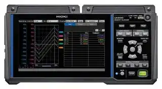


LR8450
Data Logger, CAN, Current, Humidity, Pulse, Resistance, Strain, Temperature, Voltage, 120 Channel
- Manufacturer: HIOKI
- Product type:
- SVHC: To Be Advised
- Display Type: LCD
- Product Range: -
- Data Interface: LAN, SD Card, USB
- Maximum Samples: 1 kS/s
- Data Logger Type: CAN, Current, Humidity, Pulse, Resistance, Strain, Temperature, Voltage
- No. of Channels / Inputs: 0
- Sensor / Measurement Type: -
| Delivery and price | |
|---|---|
| Units per pack | 1 |
| Price | 1650.39 € |
| Current stock | 10+ |
| Lead time | 30 days |
## **Memory HiLogger** ## LR8450 LR8450-01 ## **Datasheet** All information correct as of March 10, 2026. Company names and product names appearing in this document are trademarks or registered trademarks of various companies. All specifications are subject to change without notice. HIOKI E.E. CORPORATION 1 datasheet_LR8450E1-63B **LR8450, LR8450-01** ## Basic Specifications ## **LR8450/LR8450-01 Memory HiLogger** ## **1. General specifications** - **-1. Basic specifications** |**Product warranty**|3 years| |---|---| |**duration**|| |**Accuracy guarantee**|1 year| |**duration**|| |**Maximum number of**|4 plug-in modules + 7 wireless modules*| |**connectable modules**|*: LR8450-01 only| ||Up to a total of four U8555/LR8535 modules can be connected.| |**Connectable modules**|U8550 Voltage/Temp Unit| |**(Plug-in modules)**|U8551 Universal Unit| ||U8552 Voltage/Temp Unit| ||U8553 High Speed Voltage Unit| ||U8554 Strain Unit| ||U8555 CAN Unit| ||U8556 Current Module| ||U8557 Thermistor Module| |**Connectable modules**|LR8530 Wireless Voltage/Temp Unit| |**(Wireless modules)**|LR8531 Wireless Universal Unit| |**(LR8450-01 only)**|LR8532 Wireless Voltage/Temp Unit| ||LR8533 Wireless High Speed Voltage Unit| ||LR8534 Wireless Strain Unit| ||LR8535 Wireless CAN Unit| ||LR8536 Wireless Current Module| ||LR8537 Wireless Thermistor Module| |**Internal bufer**|Volatile memory, 256 Mwords| |**memory**|| |**Clock functionality**|Auto-calendar, automatic leap year recognition, 24-hour clock| |**Clock precision**|±1.0 s/day (at 23°C)| |**(Precision of clock**|Time can be synchronized with an NTP server to which instrument is connected.| |**displayed by**|| |**instrument as well as**|| |**start/stop times)**|| |**Time axis accuracy**|±0.2 s/day (at 23°C)| ||Connecting to an NTP server can automatically correct sampling interval deviations.| |**Backup battery**|At least 10 years for clock (reference value at 23°C)| |**service life**|| |**Operating**|Indoor use, pollution degree 2, altitude up to 2000 m (6562 ft.)| |**environment**|| |**Operating temperature**|−10°C to 50°C (14°F to 122°F), 80% RH or less (non-condensing)| |**and humidity range**|(Charging temperature range: 5°C to 35°C)| |**Storage temperature**|−20°C to 60°C (−4°F to 140°F), 80% RH or less (non-condensing)| |**and humidity range**|| All information correct as of March 10, 2026. Company names and product names appearing in this document are trademarks or registered trademarks of various companies. All specifications are subject to change without notice. HIOKI E.E. CORPORATION datasheet_LR8450E1-63B 2 **LR8450, LR8450-01** |**Dimensions**|Without any modules: 272W × 145H × 43D mm (10.72″W × 5.71″H × 1.69″D)<br>(excluding protrusions)<br>With 2 modules:<br>272W × 198H × 63D mm (10.71″W × 7.8″H × 2.78″D)<br>(excluding protrusions)<br>With 4 modules:<br>272W × 252H × 63D mm (10.71″W × 9.92″H × 2.48″D)<br>(excluding protruding parts)| |---|---| |**Weight**|Approx. 1.1 kg (38.8 oz.)| |**Standards**|Safety<br>EN 61010| ||EMC<br>EN 61326 Class A| |**Vibration resistance**|JIS D 1601:1995 5.3 (1)<br>Class 1: Passenger vehicles; conditions: Class A equivalent<br>(4 h along X-axis and 2 h along Y- and Z-axes at a vibration acceleration of 45 m/s<br>2<br>[4.6 G])| |**-2. Display**|| |**Display**|7-inch TFT color LCD (WVGA 800 × 480 dots)| |**Display resolution**<br>**(with waveform**<br>**display selected)**|Max. 20 divisions (horizontal axis) × 10 divisions (vertical axis)<br>(1 division = 36 dots [horizontal axis] × 36 dots [vertical axis])| |**Display language**|Japanese/English/Simplifed Chinese/Traditional Chinese/Korean (user-selectable)| |**Backlight service life**|Approx. 100,000 h (reference value at 23°C)| |**Backlight saver**|Turns of backlight when no key is operated for a set amount of time.<br>(Choose from Of, 30 s, 1 min., 2 min., 5 min., 10 min.)| |**Backlight brightness**|5 levels (user-selectable)| |**Waveform background**<br>**color**|<br>Dark/light (user-selectable)| ## **-3. Power supply** |**Power supply**|AC adapter<br>Z1014 AC Adapter (12 V DC ±10%)<br>AC Adapter rated supply voltage<br>100 V to 240 V AC (assuming voltage fuctuation of<br>±10%)<br>AC Adapter Rated power-supply frequency<br>50 Hz/60 Hz<br>Anticipated transient overvoltage: 2500 V| |---|---| ||Battery<br>The instrument accommodates two batteries.<br>Z1007 Battery Pack<br>(When used with AC Adapter, AC Adapter has priority.)| ||External power supply<br>10 V to 30 V DC| |**Power consumption**|Normal power<br>consumption<br>Using Z1014 AC Adapter or 12 V DC external power supply,<br>without Battery Pack<br>With LCD at maximum brightness: 8.5 VA (instrument only)<br>With LCD backlight of: 7 VA (instrument only)| ||Maximum rated power<br>When using the Z1014 AC Adapter<br>95 VA (including AC Adapter)<br>When using a 30 V DC external power supply<br>28 VA (while charging battery with LCD at maximum<br>brightness)<br>When using the Z1007 Battery Pack<br>20 VA (with LCD at maximum brightness)| All information correct as of March 10, 2026. Company names and product names appearing in this document are trademarks or registered trademarks of various companies. All specifications are subject to change without notice. HIOKI E.E. CORPORATION datasheet_LR8450E1-63B 3 **LR8450, LR8450-01** **Continuous operating** Battery With one Z1007 Battery Pack: Approx. 2 h **time** (reference value at 23°C) With two Z1007 Battery Packs: Approx. 4 h (reference value at 23°C) Conditions: With one U8551 Universal Unit connected, backlight on, voltage output off, and Z4006 connected **Charging functionality** Charging is available when the Z1007 Battery Pack is attached and the AC Adapter is connected. Charging time: Approx. 7 h (reference value at 23°C) **-4. Interface specifications** The LAN interface and USB interface (function) cannot be used at the same time. All information correct as of March 10, 2026. Company names and product names appearing in this document are trademarks or registered trademarks of various companies. All specifications are subject to change without notice. HIOKI E.E. CORPORATION 4 datasheet_LR8450E1-63B **LR8450, LR8450-01** |**LAN interface**|LAN|IEEE 802.3 Ethernet, automatic 100Base-TX/1000Base-T<br>detection<br>Auto MDI-X, DHCP, DNS support| |---|---|---| ||Connector|RJ-45| ||LAN functionality|Acquiring data and setting recording conditions with the Logger<br>Utility| |||Confguring settings and controlling recording using<br>communications commands| |||Manually acquiring data using the FTP server<br>Acquiring fles from a connected SD Memory Card or USB Drive<br>Supported protocol: FTP| |||Automatically sending data via FTP (FTP client)<br>Transferring fles saved on a connected SD Memory Card or<br>USB Drive<br>While measurement is in progress: Waveform fles (binary, text,<br>MDF)<br>After measurement has fnished: Waveform fles (binary, text,<br>MDF), numerical calculation<br>result fles<br>Supported protocol: FTP, FTPS| |||HTTP server function<br>Control mode (one instrument)<br>Displaying screen and remotely controlling instrument and<br>modules, displaying current measured values, starting/<br>stopping measurement, acquiring data via FTP, confguring<br>comment, updating instrument and modules<br>Browsing mode (up to four instruments)<br>Displaying screen, current measured values, measurement<br>status, and comments| |||Email transmission<br>The instrument will send emails at a regular interval and at the<br>following events: start trigger, stop trigger, alarm, power outage<br>recovery, internal bufer memory full, media full, wireless unit<br>communications interruption, and battery low.<br>Attachment of instantaneous value data can be enabled or<br>disabled.<br>Emails can be sent regularly at the following intervals:<br>30 min., 1 h, 12 h, 1 day.<br>Authentication protocol<br>SMTP authentication (LOGIN, PLAIN, CRAM-MD5),<br>POP authentication, no authentication<br>Encryption<br>SSL/TLS, STARTTLS, no encryption| |||XCP on Ethernet<br>Support limited to measurement mode for ECU measurement<br>and calibration software<br>ASAM e.V. MCD-1 XCP v 1.5.0 compliant| |||NTP client function<br>Time synchronization with an NTP server<br>Regular synchronization intervals: 1 h, 1 day<br>Pre-measurement synchronization function| All information correct as of March 10, 2026. Company names and product names appearing in this document are trademarks or registered trademarks of various companies. All specifications are subject to change without notice. HIOKI E.E. CORPORATION datasheet_LR8450E1-63B 5 **LR8450, LR8450-01** GENNECT Cloud collaboration function Real-time monitor Measured values can be uploaded onto the cloud server every minute. Remote control The screen of the instrument can be displayed and the instrument can be remotely operated via the cloud server. File transfer Waveform data saved in real time can be uploaded onto the cloud server. Target file: waveform file (binary, text, MDF) All information correct as of March 10, 2026. Company names and product names appearing in this document are trademarks or registered trademarks of various companies. All specifications are subject to change without notice. HIOKI E.E. CORPORATION 6 datasheet_LR8450E1-63B **LR8450, LR8450-01** |**Wireless LAN**<br>**interface**<br>**(LR8450-01 only)**|Wireless LAN|IEEE 802.11b/g/n<br>Communications range: 30 m, line of sight<br>Encryption function: WPA-PSK/WPA2-PSK, TKIP/AES<br>Available channels: between 1 and 11<br>Auto-connect function<br>Wireless LAN function can be toggled on and of.| |---|---|---| ||Supporting mode|Access point, station, wireless module connection| ||Connectable devices|Wireless modules and computer / tablet computer<br>Wireless modules and computer / tablet computer are mutually<br>exclusive.| ||Wireless LAN<br>functionality|Confguring settings and controlling recording using<br>communications commands| |||Manually acquiring data using the FTP server<br>Acquiring fles from a connected SD Memory Card or USB Drive<br>Supported protocol: FTP| |||Automatically sending data via FTP (FTP client)<br>Transferring fles saved on a connected SD Memory Card or<br>USB Drive<br>While measurement is in progress: Waveform fles (binary, text,<br>MDF)<br>After measurement has fnished:<br>Waveform fles (binary, text,<br>MDF), numerical calculation<br>result fles<br>Supported protocol: FTP, FTPS| |||HTTP server function<br>Control mode (one instrument)<br>Displaying screen and remotely controlling instrument and<br>modules, displaying current measured values, starting/<br>stopping measurement, acquiring data via FTP, confguring<br>comment, updating instrument and modules<br>Browsing mode (up to four instruments)<br>Displaying screen, current measured values, measurement<br>status, and comments| |||Email transmission<br>The instrument will send emails at a regular interval and at the<br>following events: start trigger, stop trigger, alarm, power outage<br>recovery, internal bufer memory full, media full, wireless unit<br>communications interruption, and battery low.<br>Attachment of instantaneous value data can be enabled or<br>disabled.<br>Emails can be sent regularly at the following intervals:<br>30 min., 1 h, 12 h, 1 day.<br>Authentication protocol<br>SMTP authentication (LOGIN, PLAIN, CRAM-MD5),<br>POP authentication, no authentication<br>Encryption<br>SSL/TLS, STARTTLS, no encryption| |||XCP on Ethernet<br>Support limited to measurement mode for ECU measurement<br>and calibration software<br>ASAM e.V. MCD-1 XCP v 1.5.0 compliant| |||NTP client function<br>Time synchronization with an NTP server<br>Regular synchronization intervals: 1 h, 1 day<br>Pre-measurement synchronization function| All information correct as of March 10, 2026. Company names and product names appearing in this document are trademarks or registered trademarks of various companies. All specifications are subject to change without notice. HIOKI E.E. CORPORATION datasheet_LR8450E1-63B 7 **LR8450, LR8450-01** |||GENNECT Cloud collaboration function<br>Real-time monitor<br>Measured values can be uploaded onto the cloud server<br>every minute.<br>Remote control<br>The screen of the instrument can be displayed and<br>the instrument can be remotely operated via the cloud<br>server.<br>File transfer<br>Waveform data saved in real time can be uploaded onto<br>the cloud server.<br>Target fle: waveform fle (binary, text, MDF)| |---|---|---| |**USB interface (host)**|Standard compliance|USB 2.0 compliant| ||Connectors|Series A receptacle ×2| ||Guaranteed-operation<br>options|Z4006 USB Drive (16 GB)<br>File system: FAT16, FAT32| ||Connectable devices|Keyboard, mouse, hub (1 layer), USB Drive (1 port only)| |**USB interface**<br>**(function)**|USB standard|USB 2.0 compliant| ||Connector|Series mini-B receptacle| ||USB functionality|Acquiring data and setting recording conditions with the Logger<br>Utility| |||Confguring settings and controlling recording using<br>communications commands| |||USB drive mode: Transferring data from a connected SD<br>Memory Card to a computer| |**SD card slot**|Standard compliance|SD standard-compliant slot × 1 (with SD Memory Card/SDHC<br>Memory Card support)| ||Guaranteed-operation<br>options|Z4001 (2 GB), Z4003 (8 GB)<br>File system: FAT16, FAT32| **-5. External control terminals** |**Terminal block**|Push-button type terminal block| |---|---| |**Synchronization input**|Input voltage<br>0 V to 10 V DC<br>High level: 2.0 V to 10 V; low level: 0 V to 0.8 V| ||Response pulse width<br>High period: 100 μs or greater; low period: 100 μs or greater| ||Number of terminals<br>1<br>Non-isolated (common GND with instrument)| ||Functionality<br>Synchronization control (SYNC.IN)| |**Synchronization**<br>**output**|Output format<br>CMOS output| ||Output voltage<br>High level: 2.3 V to 3.6 V; low level: 0 V to 0.5 V| ||Output pulse width<br>High period: 100 μs or greater; low period: 100 μs or greater| ||Number of terminals<br>1<br>Non-isolated (common GND with instrument)| ||Functionality<br>Synchronization control (SYNC.OUT)| All information correct as of March 10, 2026. Company names and product names appearing in this document are trademarks or registered trademarks of various companies. All specifications are subject to change without notice. HIOKI E.E. CORPORATION datasheet_LR8450E1-63B 8 **LR8450, LR8450-01** ## **External I/O** ||**Number of**<br>**terminals**|4<br>Non-isolated (common GND with instrument)| |---|---|---| ||**Input**|Input voltage<br>0 V to 10 V DC<br>High level: 2.5 V to 10 V; low level: 0 V to 0.8 V| |||Slope<br>Rising/falling (user-selectable)| |||Response pulse width<br>High period: 2.5 ms or greater; low period: 2.5 ms or greater| |||Functionality<br>Choose from of, start, stop, start/stop, trigger input, event input.| ||**Output**|Output format<br>Open-drain output (with 5 V voltage output)| |||Output voltage<br>High level: 4.0 V to 5.0 V; low level: 0 V to 0.5 V| |||Maximum switching<br>capacity<br>5 V to 10 V DC, 200 mA| |||Output pulse width<br>(Trigger output)<br>10 ms or greater| |||Functionality<br>Trigger output| |**Alarm**|**output**|Output format<br>Open-drain output (with 5 V voltage output)| |||Output voltage<br>High level: 4.0 V to 5.0 V; low level: 0 V to 0.5 V<br>Triggered by alarm<br>High output/low output (user-selectable)| |||Maximum switching<br>capacity<br>5 V to 30 V DC, 200 mA| |||Output pulse width<br>10 ms or greater| |||Number of terminals<br>8<br>Non-isolated (common GND with instrument)| |**Voltage output**||Output voltage<br>Of, 5 V ±10%, 12 V ±10%, 24 V* ±10% (user-selectable)<br>Supply current: Max. 100 mA each<br>*: 24 V output can be selected for the VOUTPUT1 terminal only.| |||Number of terminals<br>2<br>Non-isolated (common GND with instrument)| |**GND terminal**||Number of terminals<br>10 (common GND)| |**2. Recording**||| |**2. Recording**|| |---|---| |**Recording mode**|Normal| |**Recording intervals**|1 ms*, 2 ms*, 5 ms*, 10 ms, 20 ms, 50 ms, 100 ms, 200 ms, 500 ms, 1 s, 2 s, 5 s, 10 s,| ||20 s, 30 s, 1 min., 2 min., 5 min., 10 min., 20 min., 30 min., 1 h| ||*: Setting available only when using a module with data refresh intervals including 1 ms.| |**Data refresh interval**|Automatically- or user-selected value per module| ||Automatically-selected value: The optimal data refresh interval is automatically selected| ||based on the recording interval setting.<br>User-selected value:<br>Available settings depend on module specifcations.| |**Repeat recording**|Of/On (user-selectable)| ||On: Recording resumes after recording stops (due to stop trigger conditions or the| ||completion of measurement for the set recording time). Recording repeats until the| ||**STOP**key is pressed.<br>Of: Recording is performed once until it stops.| All information correct as of March 10, 2026. Company names and product names appearing in this document are trademarks or registered trademarks of various companies. All specifications are subject to change without notice. HIOKI E.E. CORPORATION datasheet_LR8450E1-63B 9 **LR8450, LR8450-01** |**Specifed time/**<br>**continuous**|Specifed time<br>The recording time is set in days, hours, minutes, and seconds.<br>The time can be set up to the maximum capacity of the internal<br>bufer memory (total of 256 M).| |---|---| ||Continuous<br>Recording is performed once until it is stopped.<br>If the maximum capacity of the internal bufer memory is<br>exceeded, the memory will be overwritten.| |**Waveform recording**|The last 256 M data points (when recording 1 analog channel; if recording_n_channels,<br>256 M/_n_data points) are saved in the internal bufer memory.<br>The user can scroll through and view data stored in the internal bufer memory.<br>Alarm source data recording can be toggled on and of.*<br>1<br>The numerical expression of the number of channels (_n_)<br>_n_= (Number of analog channels) + (number of pulse channels) × 2<br>+ (number of logic channels) × 1<br>+ (number of waveform calculation channels) × 4<br>+ (number of CAN channels*<br>2) + 26*<br>3<br>*1: CAN channel alarm source data cannot be recorded.<br>*2: Calculated as 2 channels when using 32 bits or 4 channels when using 64 bits.<br>*3: Added when the alarm source setting is enabled.| |**Backup of recorded**<br>**data**|None| All information correct as of March 10, 2026. Company names and product names appearing in this document are trademarks or registered trademarks of various companies. All specifications are subject to change without notice. HIOKI E.E. CORPORATION 10 datasheet_LR8450E1-63B **LR8450, LR8450-01** ## **3. Display** |**3. Display**|| |---|---| |**Sheet function**|Can switch among display sheets for all channels and individual units (for CAN Units, up<br>to 4 sub sheets with 125 channels each).<br>Maximum number of measurement channels on all-channel display sheet<br>: 120 Analog/CAN channels, 30 waveform calculation channels, 8 pulse/logic channels,<br>8 alarm channels| |**Waveform display**<br>**screen**|Time-axis waveform<br>display<br>Simultaneous display of gages and settings (channel<br>representative settings and display settings)| ||Simultaneous display<br>of time-axis waveforms<br>and values<br>Instantaneous values, cursor values, or numerical calculation<br>values (user-switchable)| ||Numerical display<br>Simultaneous display of instantaneous values and statistical<br>values| ||Alarm display<br>Display of alarm status and alarm history| |**Display format**|Time-axis waveform display:1screen<br>X-Y waveform display:<br>1 screen| |**X-Y composite**|Composite up to 8 waveforms.| |**Numerical display**<br>**format**|SI units, decimal, or exponent (user-selectable)<br>When decimal is selected, the number of decimal places to display can be set (values<br>will then be rounded to the set number of places).| |**Waveform colors**|24 colors| |**Zooming in and out on**<br>**the waveform display**|<br>Horizontal axis<br>2 ms, 5 ms, 10 ms, 20 ms, 50 ms, 100 ms, 200 ms, 500 ms, 1 s,<br>2 s, 5 s, 10 s, 20 s, 30 s, 1 min., 2 min., 5 min., 10 min., 20 min.,<br>30 min., 1 h, 2 h, 5 h, 10 h, 12 h, 1 day/division| ||Vertical axis<br>Number of divisions per screen: 10<br>Setting method<br>Select position or upper and lower limits for each channel.<br>(Waveform calculation channels: upper and lower limits only)<br>• When setting by position: Set zoom factor and zero position.<br>Zoom factor: 1/2×, 1×, 2×, 5×, 10×, 20×, 50×, 100×<br>Zero position: −50% to 150% (with a zoom factor of 1×)<br>• When setting by upper/lower limit: Set the upper and lower<br>limit.| |**Waveform scrolling**|The display can be scrolled left and right both during recording and while recording is<br>stopped (during waveform rendering only).| |**Monitor display**|The user can check instantaneous values and waveforms without recording data to<br>memory (the monitor of the trigger standby state is available).| |**Wireless module**<br>**status indication**<br>**(LR8450-01 only)**|Indicates the battery remaining and the radio-wave strength, in the four levels, of the<br>wirelessly connected modules.| All information correct as of March 10, 2026. Company names and product names appearing in this document are trademarks or registered trademarks of various companies. All specifications are subject to change without notice. HIOKI E.E. CORPORATION 11 datasheet_LR8450E1-63B **LR8450, LR8450-01** ## **4. Files** ## **-1. Saving** |**4. Files**<br>**-1. Saving**|| |---|---| |**Save destinations**|SD Memory Card/USB Drive (user-selectable)| |**Filenames**|Up to 8 single-byte characters<br>Automatic numbering, adding date and/or title comment (user-selectable)| |**Auto saving**|Waveform data (real-time saving)<br>Of, binary format, text format, or MDF format (user-selectable)<br>Numerical calculation results (saved after recording)<br>Of or text format (user-selectable)<br>When text format is selected, the user can choose whether to save all calculations<br>in one fle or to save each calculation in its own fle.| ||Priority save<br>destination<br>SD Memory Card/USB Drive (user-selectable)<br>The user can choose whether to give priority to the SD Memory<br>Card or the USB Drive for saving data when both are inserted.| ||Delete and save<br>On/Of (user-selectable)<br>Of: The system will stop saving data when the SD Memory<br>Card or USB Drive starts to run out of available space.<br>On: When the SD Memory Card or USB Drive starts to run<br>out of available space, the system will delete the oldest<br>waveform fle (binary, text, or MDF) and then continue<br>saving data. When both an SD Memory Card and a USB<br>Drive are inserted, the system will perform delete and<br>save on the media that has been set as the priority save<br>destination only.| ||Folder splitting<br>Disabled, 1 day, 1 week, or 1 month (user-selectable)| ||File splitting<br>Disabled, enabled, or timed (user-selectable)<br>Disabled: Data for each recording session is saved in its own<br>fle.<br>Enabled: Data for each set period of time is saved in its own<br>fle, starting with the start of measurement.<br>Split time: Day, hour, or minute (user-selectable)<br>Timed:<br>Data will be segmented at intervals of the segment<br>time based on the previously set reference time and<br>saved in separate fles.<br>Reference time: Set in hours and minutes.<br>Split time:<br>1 min, 2 min, 5 min, 10 min, 15 min, 20 min,<br>30 min, 1 h, 2 h, 3 h, 4 h, 6 h, 8 h, 12 h, 1 d| ||External media eject<br>(SD Memory Card/<br>USB Drive)<br>External media can be ejected during real-time saving by<br>activating a button on the screen and confrming a message.<br>• When both an SD Memory Card and a USB Drive are inserted<br>and the media set as the priority save destination is ejected,<br>the system will continue to save data on the other media.<br>• When either an SD Memory Card or a USB Drive is inserted<br>and the media set as the priority save destination is ejected,<br>the system will stop saving data. If external media is reinserted<br>under these conditions, the system will continue saving data<br>remaining in the internal bufer memory to a diferent fle.| ||Data protection<br>Yes (valid only when the Z1007 Battery Pack is installed)<br>If the remaining battery life declines during real-time saving,<br>the system will close the fle and stop saving data (although<br>measurement operation will continue).| All information correct as of March 10, 2026. Company names and product names appearing in this document are trademarks or registered trademarks of various companies. All specifications are subject to change without notice. HIOKI E.E. CORPORATION 12 datasheet_LR8450E1-63B **LR8450, LR8450-01** |**Manual saving**|Data is saved when the**SAVE**key is pressed.<br>The user can choose either selective save or immediate save as the operation to perform<br>when the**SAVE**key is pressed.<br>Selective save<br>The user will be prompted to choose what to save: settings,<br>waveform data (binary format), waveform data (text format),<br>waveform data (MDF format), A2L fle, numerical calculation<br>results (all calculations in one fle or each calculation in its own<br>fle), display image (PNG format).<br>Immediate save<br>Data will be saved immediately when the**SAVE**key is pressed.<br>The type of data to save is set in advance along with the format<br>and range.<br>Filenames can be entered when saving data.| |---|---| |**Decimation**<br>**(text format only)**|Decimate and save<br>Of or a value from 1/2 to 1/100,000 (user-selectable)<br>Saved data<br>Select from instantaneous values and statistical values.<br>When statistical values are selected:<br>Instantaneous values, maximum values, minimum values, and<br>average values will be saved for the thinning interval.| ## **-2. Loading data** **Loading saved data** The user can specify a position and then load up to 256 M data points of previously saved text-format data (when recording 1 analog channel; if recording _n_ channels, 256 M/ _n_ data points). **Setting conditions** Setting conditions files saved with the instrumen can be loaded.* Loadable items: Measurement setting, communication setting, system setting, wireless module configuration - *: Available only when the module configuration is the same as those at the time when the setting condition was saved. ## **5. Calculations** |**Numerical**<br>**calculations**|Number of calculations<br>Up to 10 calculations simultaneously| |---|---| ||Calculation content<br>Average value, peak-to-peak value, maximum value, maximum<br>value time, minimum value, minimum value time, integral*<br>1,<br>integration*<br>1, moving average*<br>2, on time*<br>2, of time*<br>2, on count*<br>2,<br>of count*<br>2<br>*1: Total, positive, negative, or absolute value (user-selectable)<br>*2: Threshold values can be set for individual channels.| ||Calculation range<br>During recording:<br>Calculations performed for all data during recording<br>After recording has stopped:<br>Calculations performed for all data in the internal bufer<br>memory, or for data in a calculation range specifed by<br>the A/B cursors (on the vertical axis)| ||Time split calculation<br>Disabled, enabled, or timed (user-selectable)<br>Disabled: Calculations performed for all data during recording<br>Enabled: Data for each segment of time, starting with the start<br>of measurement<br>Split time: Set DD HH:MM format<br>Timed:<br>Calculations will be made at intervals of the segment<br>time based on the previously set reference time.<br>Reference time: Set in hours and minutes.<br>Split time:<br>1 min, 2 min, 5 min, 10 min, 15 min, 20 min,<br>30 min, 1 h, 2 h, 3 h, 4 h, 6 h, 8 h, 12 h, 1 d| All information correct as of March 10, 2026. Company names and product names appearing in this document are trademarks or registered trademarks of various companies. All specifications are subject to change without notice. HIOKI E.E. CORPORATION datasheet_LR8450E1-63B 13 **LR8450, LR8450-01** **Waveform** Calculation content The following calculations can be set: **calculations** • Four arithmetic operations* among channels • Moving average, simple average, integral, and integration of any channel Calculated values are recorded as data for the calculation channels (W1 through W30). (Calculations are performed at the same time as measurement. Values cannot be recalculated after measurement.) *: Calculation expression (A∗CHa B∗CHb C∗CHc D∗CHd) E where A, B, C, D, E: User-specified constants CHa, CHb, CHc, CHd: User-specified measurement channels : Plus (+), minus (−), multiplication (*), or division(/) (one operation) : Plus (+), minus (−), multiplication (*), division(/), or exponentiation (^) (one operation) ## **6. Triggers** |**Trigger method**|Digital comparison method| |---|---| |**Trigger timing**|Start, stop, or start & stop| |**Trigger conditions**|AND/OR operation performed on trigger source, interval trigger, or external trigger<br>When triggers are disabled, free run| |**Trigger sources**|Analog, pulse, logic, waveform calculations, CAN (up to 100)| |**Trigger types**|Analog, pulse,<br>waveform calculations,<br>CAN<br>Level triggers<br>Trigger activated by rising or falling edge at set level<br>Window triggers<br>Set by trigger level upper limit and lower limit<br>Trigger activated when value leaves area or when value<br>enters area| ||Logic, CAN<br>Trigger activated when patterns of 1/0/X match (where “X”<br>indicates either)| |**Interval triggers**|Trigger activated for set recording interval after setting days/hours/minutes/seconds| |**External triggers**|Trigger activated by rising or falling edge at set level in external input signal<br>Rising/falling (user-selectable)| |**Trigger response time**|With plug-in module(s):<br>(Recording interval or data refresh interval, whichever is longer) × 2<br>+ 1 ms + (analog response time)*<br>1<br>When using the wireless modules (LR8450-01 only):<br>(Recording interval or data refresh interval, whichever is longer) × 2<br>+ (wireless response time)*<br>2+ (analog response time)*<br>1<br>*1: Depending on flter settings (U8554 with a data refresh interval of 5 ms and low-pass<br>flter of 120 Hz).<br>*2: When the radio-wave state is in good condition, 1s.| |**Trigger level**<br>**resolution**|Analog<br>0.1% f.s. (f.s. = 10 divisions)<br>The trigger level can be set in units of the measurement<br>resolution for the U8556 Current Module and the LR8536<br>Wireless Current Module.<br>When performing temperature conversion with the U8557 or<br>LR8537 Thermistor Module, the resolution is 0.2°C.| ||Pulse<br>Integration 1_c_, rotational speed 1/_n_(where_n_= pulse count per<br>rotation setting)| |**Pre-triggers**|Set day/hours/minutes/seconds.<br>Can be set during real-time saving.| All information correct as of March 10, 2026. Company names and product names appearing in this document are trademarks or registered trademarks of various companies. All specifications are subject to change without notice. HIOKI E.E. CORPORATION 14 datasheet_LR8450E1-63B **LR8450, LR8450-01** ## **7. Alarms** |**7. Alarms**||| |---|---|---| |**Alarm conditions**|Set separately for ALM1 to ALM8<br>The system will output an alarm when any of the following conditions are satisfed:<br>• AND/OR operation performed on alarm sources<br>• Low battery<br>• Thermocouple wire break<br>• Disruption of communications with wireless modules (LR8450-01 only)|| |**Alarm sources**|Analog, pulse, logic, waveform calculations, CAN (up to 100)|| |**Disruption of**<br>**communications with**<br>**wireless modules**<br>**(LR8450-01 only)**|If communicates with a wireless module are disrupted<br>Of/Now/3 min. (user-selectable)<br>Now: Outputs an alarm upon a communications disruption<br>3 min.: Outputs an alarm if a communication disruption continues for 3 minutes.|| |**Low remaining**<br>**battery life**|The system will output an alarm when the remaining battery life of the instruments or a<br>wireless module decline.|| |**Thermocouple wire**<br>**break**|The system will output an alarm when a thermocouple wire break occurs (when the<br>thermocouple wire break detection setting is enabled).|| |**Types of alarms**|Analog, pulse,<br>waveform calculations,<br>CAN|<br>Level<br>The system will output an alarm following a rising or<br>falling edge at set level.| |||Window<br>Set upper limit and lower limit.<br>The system will output an alarm when value exits area or<br>when value enters area.| |||Slope<br>Set a level and a time interval<br>The system will output an alarm when the rate of change<br>(level per unit time) continues to exceed the specifed<br>change rate during the set time interval.| |||Slope 2p (Amount in change)<br>Set a level, a time interval, and a slope.<br>The system will output an alarm when the amount of<br>change in the set time interval is greater than or less than<br>the set level value.| ||Logic|The system will output an alarm when patterns of 1, 0, and X<br>match (where “X” indicates either).| |**Alarm flter**|Apply a flter to the results of AND/OR operations performed on alarm sources.<br>Set based on sample count (Of, 2 to 1000).<br>The system will output an alarm if the alarm state continues for the set number of samples.|| |**Alarm setting**<br>**resolution**|Analog<br>0.1% f.s. (f.s. = 10 divisions)|| ||Pulse<br>Integration 1_c_, rotational speed 1/_n_(where_n_= pulse count per<br>rotation setting)|| |**Alarm retention**|On/Of (user-selectable)<br>Clear alarms: When alarm retention is On, alarms will be cleared without stopping<br>recording.|| |**Alarm tone**|On/Of (user-selectable)|| |**Alarm output**<br>**response time**|When using the plug-in modules<br>(Recording interval or data refresh interval, whichever is longer) × 2 + 1 ms<br>+ (analog response time)*<br>1<br>When using the wireless modules (LR8450-01 only)<br>(Recording interval or data refresh interval, whichever is longer) × 2<br>+ (wireless response time)*<br>2+ (analog response time)*<br>1<br>*1: Depending on flter settings (U8554 with a data refresh interval of 5 ms and low-pass<br>flter of 120 Hz).|| *2: When the radio-wave state is in good condition, 1s. All information correct as of March 10, 2026. Company names and product names appearing in this document are trademarks or registered trademarks of various companies. All specifications are subject to change without notice. HIOKI E.E. CORPORATION 15 datasheet_LR8450E1-63B **Plug-in Modules** ## **8. Synchronous operation** **Instrument** Start/stop, triggers, and sampling are synchronized among multiple instruments (using the **synchronization** SYNC.OUT and SYNC.IN terminals). • Trigger synchronization time: Within (recording interval × 2) samples • Can not be used with wireless modules **Number of** 5 (Up to four secondary instruments can operate in synchronization with one primary **instruments that can** instrument.) **be synchronized Configurable** No limitations (can be set from 1 ms) **recording interval** ## **9. Other functionality** |**Even mark function**|Even mark entry<br>method<br>Assigns event marks when one of the following events occurs.<br>(1) Pressing the**START**key<br>(2) With**[Mark]**chosen on the screen, pressing the**ENTER**<br>key.<br>(3) Inputting a signal to an external input terminal<br>(4) If an alarm is outputted (can be toggled between on and<br>of).| |---|---| ||Number of inputs<br>Up to 1000 inputs per measurement| |**Waveform search**<br>**function**|Search waveforms and display target location in the center of the waveform screen.| ||Search conditions<br>Search by choosing level, window, maximum value, minimum<br>value, local maximum value, or local minimum value.| ||Search range<br>All data in the internal bufer memory or data between the A/B<br>cursors (on the vertical axis)| ||Search targets<br>Analog, pulse, logic, waveform calculations| |**Jump function**|Specify the event mark, A/B cursor position, trigger point, or waveform display position to<br>display in the center of the waveform screen.| |**Cursor measurement**<br>**function**|Cursor display<br>All channels or specifed channels (user-selectable)| ||Cursor movement<br>A, B, or simultaneous (user-selectable)| ||Types of cursors<br>Vertical or horizontal (user-selectable)<br>Vertical<br>Display of the following values:<br>• Times at the A and B cursors<br>• Measured values at the A and B cursors<br>• Time lag between the A and B cursors<br>• Reciprocals of the time lags (frequencies) between any two<br>points selected from among the trigger point, A cursor, and B<br>cursor<br>• Diferences in measured values between the A and B cursors<br>Horizontal<br>Display of the following values acquired across the selected<br>channels:<br>• Values at the A and B cursor<br>• Diference between values at the A and B cursors| All information correct as of March 10, 2026. Company names and product names appearing in this document are trademarks or registered trademarks of various companies. All specifications are subject to change without notice. HIOKI E.E. CORPORATION 16 datasheet_LR8450E1-63B **Plug-in Modules** |**Scaling function**|Scaling settings can be confgured separately for each channel.| |---|---| ||Analog<br>Set by conversion rate, by 2 points, by strain gage rating (Strain<br>Unit only), or by sensitivity (user-selectable)| ||Pulse (integration)<br>Set by physical value per pulse or number of pulses per physical<br>value (user-selectable)| ||Pulse (rotational<br>speed)<br>Set by conversion rate or by 2 points (user-selectable)| ||Temperature display in<br>degrees Fahrenheit<br>When display language is set to English, Fahrenheit<br>temperature scaling is available.| |**Comment entry**<br>**function**|Enter titles and channel-specifc comments (values, alphabetical characters, and<br>symbols).| |**Start state retention**<br>**function**|On/Of (user-selectable)<br>When enabled, the system will enter the re-start state and automatically start recording if<br>the power is turned of during recording and then turned back on (or the trigger standby<br>state if using a trigger).| |**Startup auto-**<br>**measurement**<br>**function**|On/of (user-selectable)<br>When the function is enabled, the instrument will automatically start measurement on<br>startup (get into the trigger standby state when the trigger setting is enabled)| |**Functionality for**<br>**saving setting**<br>**conditions**|Up to fve groups of setting conditions can be saved in the instrument's internal backup<br>memory.| |**Auto-setup function**|Setting conditions saved in the instrument's memory or on an SD Memory Card or a USB<br>Drive can be automatically loaded when the instrument is powered on.<br>If there are setting conditions stored in the instrument's memory as well as on an SD<br>Memory Card and a USB Drive, setting conditions have the following precedence:<br>instrument memory, SD Memory Card, and USB Drive.| |**Prevention of**<br>**inadvertent START/**<br>**STOP key operation**|When the**START**or**STOP**key is pressed, the system will display a message asking<br>whether the user wishes to start or stop measurement.<br>Confrmation message: Enable/disable (user-selectable)| |**Key lock function**|Disables operation keys (enabled/disabled by pressing and holding the**ESC**key for 3 s or<br>more).| |**Beep tone**|On/Of (user-selectable)| |**Self-check function**|Can check keys, LCD, ROM/RAM, LAN, media, and modules.| |**Display of horizontal**<br>**axis (time values)**|Horizontal axis (time value) display can be set to time, date, or data point count.<br>Setting is applied when text data is saved.| |**Measurement**<br>**start/stop time**<br>**specifcation function**|Measurement start and stop conditions can be set.<br>Specifed date<br>•Start and stop times (year, month, day, hour, and minute) can be set.| |**Confguration**<br>**navigation (Quick**<br>**Set) function**|Wireless module registration guide (LR8450-01 only), countermeasures against wireless<br>communication failure (LR8450-01 only), connection diagram display (strain gage,<br>external terminals), loading setting conditions| |**Power supply**<br>**frequency flter**<br>**function**|50 Hz/60 Hz selection| All information correct as of March 10, 2026. Company names and product names appearing in this document are trademarks or registered trademarks of various companies. All specifications are subject to change without notice. HIOKI E.E. CORPORATION 17 datasheet_LR8450E1-63B **Plug-in Modules** ## **10. Input** **Pulse/logic input** ||Number of channels|8 channels (common GND, non-isolated)| |---|---|---| |||Exclusive setting for pulse/logic input for individual channels| ||Terminal block|Push-button type terminal block| ||Adaptive input format|Non-voltage contact, open collector (PNP open collector| |||requires external resistor), or voltage input| ||Maximum input voltage|0 V to 42 V DC| ||Input resistance|1.1 MΩ±5%| ||Detection level|2 levels (user-selectable)| |||High: 1.0 V or greater; low: 0 to 0.5 V| |||High: 4.0 V or greater; low: 0 to 1.5 V| **Pulse input** Measurement range, maximum resolution, measurable range, measurement accuracy **==> picture [387 x 29] intentionally omitted <==** **----- Start of picture text -----**<br> Measurement Maximum Measurement<br>Range (f.s.) Measurable range<br>target resolution accuracy<br>**----- End of picture text -----**<br> |**Measurement**<br>**target**|**Range (f.s.)**|**Maximum**<br>**resolution**|**Measurable range**|**Measurement**<br>**accuracy**| |---|---|---|---|---| |||||| |Integration|1000 M counts|1 count|0 to 1000 M counts|±1 count| |Rotational<br>speed|5000/_n_(r/s)|1/_n_(r/s)|0 to 5000/_n_(r/s)|±1/_n_(r/s)| ||300,000/_n_(r/min.)|60/_t_0_n_(r/min.)|0 to 300,000/_n_(r/min.)|±60/_t_0_n_(r/min)| ||_n_: Number of pulses per rotation (1 to 1000)<br>_t_0: Smoothing setting (1 to 60 s)|||| ||Pulse input period<br>With flter of:<br>200 μs or greater (100 μs or greater during high and low<br>interval)<br>With flter on:<br>100 ms or greater (50 ms or greater during high and low<br>interval)| |---|---| ||Slope<br>Set rising/falling for each channel.| ||Measurement mode<br>Integration (addition, instantaneous), rotational speed| ||Integration<br>Addition: Counts the number of pulses input from start of<br>measurement.<br>Instantaneous: Counts the number of pulses input within each<br>recording interval (integrated value is reset for<br>each rotational interval).| ||Rotational speed<br>r/s:<br>Counts the number of input pulses during 1 s and<br>calculates the rotational speed.<br>r/min.: Counts the number of input pulses during 1 min. and<br>calculates the rotational speed.| ||Smoothing function<br>Select value from 1 s to 60 s (valid only when set to rotational<br>speed and r/min.).| ||Chatter prevention flter<br>Set to On/Of for each channel.| |**Logic input**|Measurement mode<br>Records 1 or 0 for each recording interval.| ## **11. Accessories and options** |**Accessories**|See “Accessories” in the Quick Start Manual.| |---|---| |**Options**|See “Options (sold separately)” in the Quick Start Manual.| All information correct as of March 10, 2026. Company names and product names appearing in this document are trademarks or registered trademarks of various companies. All specifications are subject to change without notice. HIOKI E.E. CORPORATION 18 datasheet_LR8450E1-63B **Plug-in Modules** ## Plug-in Module Specifications ## **U8550 Voltage/Temp Unit** ## **1. General specifications** |**Compatible logger**|LR8450/LR8450-01 Memory HiLogger|| |---|---|---| |**Operating**|Indoor use, pollution degree 2, altitude up to 2000 m (6562 ft.)|| |**environment**||| |**Operating temperature**|−10°C to 50°C (14°F to 122°F), 80% RH or less (non-condensing)|| |**and humidity range**||| |**Storage temperature**|−20°C to 60°C (−4°F to 140°F), 80% RH or less (non-condensing)|| |**and humidity range**||| |**Standards**|Safety: EN 61010|| ||EMC: EN 61326, Class A|| |**Standard compliance**|Thermocouples: JIS C1602:2015, IEC 60584-1:2013|| |**Vibration resistance**|JIS D 1601:1995:1995 5.3 (1)|| ||Class 1: Passenger vehicles; conditions: Class A equivalent|| ||(4 h along X-axis and 2 h along Y- and Z-axes at a vibration acceleration of 45 m/s|2| ||[4.6 G])|| |**Dimensions**|Approx. 134W × 70H × 63D mm (5.28″W × 2.76″H × 2.48″D) (including cover)|| |**Weight**|Approx. 345 g (12.2 oz.)|| |**Product warranty**|3 years|| |**duration**||| |**Accessories**|Instruction Manual|| ||Installation screws × 2|| |**Options**|Z2000 Humidity Sensor|| ## **2. Input, output, and measurement specifications** - **-1. Basic specifications** |**Number of input**|15 (Set voltage, thermocouple, or humidity for each channel.)| |---|---| |**channels**|| |**Input terminals**|M3 screw-type terminal block (2 terminals per channel), outftted with terminal block| ||cover| |**Measurement target**|Voltage| ||Thermocouples (K, J, E, T, N, R, S, B, C)| ||Humidity (using the Z2000 Humidity Sensor)| |**Input type**|Scanning by semiconductor relays, foating unbalanced input| ||All channels isolated| |**A/D resolution**|16 bits| |**Maximum input**|±100 V DC| |**voltage**|| |**Maximum channel-to-**|300 V DC| |**channel voltage**|| |**Maximum rated line-**|300 V AC, DC (Measurement Category II)| |**to-ground voltage**|Between any input channel (+, −) and the instrument (LR8450/LR8450-01) or between| ||any two modules| ||Anticipated transient overvoltage: 2500 V| All information correct as of March 10, 2026. Company names and product names appearing in this document are trademarks or registered trademarks of various companies. All specifications are subject to change without notice. HIOKI E.E. CORPORATION 19 datasheet_LR8450E1-63B **Plug-in Modules** |**Input resistance**|10 MΩor greater (10 mV f.s. to 2 V f.s. voltage ranges, all thermocouple ranges)| |---|---| ||1 MΩ±5% (10 V f.s. to 100 V f.s. voltage ranges, 1-5 V f.s. voltage range, humidity| ||range)| |**Allowable signal**|1 kΩor less| |**source resistance**|| |**Reference junction**|Internal/external (user-selectable) (during thermocouple measurement)| |**compensation**|| |**Thermocouple wire**|The system will check for wire breaks at the date refresh intervals during thermocouple| |**break detection**|measurement.| ||On/Of (user-selectable) (set for entire module)| ||Detection current: 5 μA ±20%<br>No current fows while acquiring measurement data.| ||(Setting not available when the data refresh interval is set to 10 ms.)| |**Data refresh interval**|10 ms*, 20 ms, 50 ms, 100 ms, 200 ms, 500 ms, 1 s, 2 s, 5 s, 10 s| ||*: Setting available when thermocouple wire break detection is disabled.| |**Digital flters**|The digital flter notch frequency is automatically set as described in the following table| ||according to the data refresh interval, Wire break detection setting, and power supply<br>frequency flter setting:| ||–: Setting not available| |**Power**<br>|**Wire break**<br>|<br>**Data refresh interval**|<br>**Data refresh interval**|<br>**Data refresh interval**|<br>**Data refresh interval**|<br>**Data refresh interval**|<br>**Data refresh interval**|<br>**Data refresh interval**|<br>**Data refresh interval**|<br>**Data refresh interval**|<br>**Data refresh interval**| |---|---|---|---|---|---|---|---|---|---|---|---| |**supply**<br>**frequency**<br>**flter setting**|**detection**<br>**setting**|**10 ms**|**20 ms**|**50 ms**|**100 ms**|**200 ms**|**500 ms**|**1 s**|**2 s**|**5 s**|**10 s**| |60 Hz|Of|20.8 k|6.94 k|2.98 k|2.37 k|739|60|60|60|60|60| ||On|–|20.8 k|6.94 k|2.98 k|2.37 k|739|60|60|60|60| |50 Hz|Of|20.8 k|6.94 k|2.98 k|2.37 k|739|50|50|50|50|50| ||On|–|20.8 k|6.94 k|2.98 k|2.37 k|739|50|50|50|50| |||Unit: Hz|||||||||| **Zero-adjustment** Cancels the offset of the product’s internal measurement circuitry. ## **-2. Accuracy specifications** |**Accuracy guarantee**|Accuracy guarantee|1 year| |---|---|---| |**conditions**|duration|| ||Accuracy guarantee|23°C ±5°C (73°F ±9°F), 80% RH or less| ||temperature and|| ||humidity range|| ||Warm-up time|At least 30 minutes after connecting to the LR8450/LR8450-01| |||Memory HiLogger and turning on the instrument| The conditions have been specified with after zero-adjustment finished and the notch frequency set to 50 Hz/60 Hz (see notch frequency table in “Digital filters”). All information correct as of March 10, 2026. Company names and product names appearing in this document are trademarks or registered trademarks of various companies. All specifications are subject to change without notice. HIOKI E.E. CORPORATION 20 datasheet_LR8450E1-63B **Plug-in Modules** ## **Measurement range, maximum resolution, measurable range, and measurement accuracy figures** **==> picture [435 x 29] intentionally omitted <==** **----- Start of picture text -----**<br> Measurement Maximum Measurement<br>Type Range Measurable range<br>target resolution accuracy<br>**----- End of picture text -----**<br> |**Measurement**<br>**target**|**Type**|**Range**|**Maximum**<br>**resolution**|**Measurable range**|**Measurement**<br>**accuracy**| |---|---|---|---|---|---| ||||||| |Voltage|–|10 mV f.s.|500 nV|−10 mV to 10 mV|±10 µV| |||20 mV f.s.|1 μV|−20 mV to 20 mV|±20 µV| |||100 mV f.s.|5 μV|−100 mV to 100 mV|±50 µV| |||200 mV f.s.|10 μV|−200 mV to 200 mV|±100 µV| |||1 V f.s.|50 μV|−1 V to 1 V|±500 µV| |||2 V f.s.|100 μV|−2 V to 2 V|±1 mV| |||10 V f.s.|500 μV|−10 V to 10 V|±5 mV| |||20 V f.s.|1 mV|−20 V to 20 V|±10 mV| |||100 V f.s.|5 mV|−100 V to 100 V|±50 mV| |||1-5 V f.s.|500 μV|1 V to 5 V|±5 mV| |Thermocouple<br>(Not including<br>accuracy of<br>reference<br>junction<br>compensation)|K|100°C f.s.|0.01°C|Greater than or equal to −100°C<br>and less than 0°C|±0.7°C| |||||Greater than or equal to 0°C and<br>less than or equal to 100°C|±0.5°C| |||500°C f.s.|0.05°C|Greater than or equal to −200°C<br>and less than −100°C|±1.4°C| |||||Greater than or equal to −100°C<br>and less than 0°C|±0.7°C| |||||Greater than or equal to 0°C and<br>less than or equal to 500°C|±0.5°C| |||2000°C f.s.|0.1°C|Greater than or equal to −200°C<br>and less than −100°C|±1.4°C| |||||Greater than or equal to −100°C<br>and less than 0°C|±0.7°C| |||||Greater than or equal to 0°C and<br>less than 500°C|±0.5°C| |||||Greater than or equal to 500°C<br>and less than or equal to 1350°C|±0.7°C| ||J|100°C f.s.|0.01°C|Greater than or equal to −100°C<br>and less than 0°C|±0.7°C| |||||Greater than or equal to 0°C and<br>less than or equal to 100°C|±0.5°C| |||500°C f.s.|0.05°C|Greater than or equal to −200°C<br>and less than −100°C|±0.9°C| |||||Greater than or equal to −100°C<br>and less than 0°C|±0.7°C| |||||Greater than or equal to 0°C and<br>less than or equal to 500°C|±0.5°C| |||2000°C f.s.|0.1°C|Greater than or equal to −200°C<br>and less than −100°C|±0.9°C| |||||Greater than or equal to −100°C<br>and less than 0°C|±0.7°C| |||||Greater than or equal to 0°C and<br>less than or equal to 1200°C|±0.5°C| All information correct as of March 10, 2026. Company names and product names appearing in this document are trademarks or registered trademarks of various companies. All specifications are subject to change without notice. HIOKI E.E. CORPORATION datasheet_LR8450E1-63B 21 **Plug-in Modules** **==> picture [435 x 29] intentionally omitted <==** **----- Start of picture text -----**<br> Measurement Maximum Measurement<br>Type Range Measurable range<br>target resolution accuracy<br>**----- End of picture text -----**<br> |**Measurement**<br>**target**|**Type**|**Range**|**Maximum**<br>**resolution**|**Measurable range**|**Measurement**<br>**accuracy**| |---|---|---|---|---|---| ||||||| |Thermocouple<br>(Not including<br>accuracy of<br>reference<br>junction<br>compensation)|E|100°C f.s.|0.01°C|Greater than or equal to −100°C<br>and less than 0°C|±0.7°C| |||||Greater than or equal to 0°C and<br>less than or equal to 100°C|±0.5°C| |||500°C f.s.|0.05°C|Greater than or equal to −200°C<br>and less than −100°C|±0.9°C| |||||Greater than or equal to −100°C<br>and less than 0°C|±0.7°C| |||||Greater than or equal to 0°C and<br>less than or equal to 500°C|±0.5°C| |||2000°C f.s.|0.1°C|Greater than or equal to −200°C<br>and less than −100°C|±0.9°C| |||||Greater than or equal to −100°C<br>and less than 0°C|±0.7°C| |||||Greater than or equal to 0°C and<br>less than or equal to 1000°C|±0.5°C| ||T|100°C f.s.|0.01°C|Greater than or equal to −100°C<br>and less than 0°C|±0.7°C| |||||Greater than or equal to 0°C and<br>less than or equal to 100°C|±0.5°C| |||500°C f.s.|0.05°C|Greater than or equal to −200°C<br>and less than −100°C|±1.4°C| |||||Greater than or equal to −100°C<br>and less than 0°C|±0.7°C| |||||Greater than or equal to 0°C and<br>less than or equal to 400°C|±0.5°C| |||2000°C f.s.|0.1°C|Greater than or equal to −200°C<br>and less than −100°C|±1.4°C| |||||Greater than or equal to −100°C<br>and less than 0°C|±0.7°C| |||||Greater than or equal to 0°C and<br>less than or equal to 400°C|±0.5°C| ||N|100°C f.s.|0.01°C|Greater than or equal to −100°C<br>and less than 0°C|±1.1°C| |||||Greater than or equal to 0°C and<br>less than or equal to 100°C|±0.9°C| |||500°C f.s.|0.05°C|Greater than or equal to −200°C<br>and less than −100°C|±2.1°C| |||||Greater than or equal to −100°C<br>and less than 0°C|±1.1°C| |||||Greater than or equal to 0°C and<br>less than or equal to 500°C|±0.9°C| |||2000°C f.s.|0.1°C|Greater than or equal to −200°C<br>and less than −100°C|±2.1°C| |||||Greater than or equal to −100°C<br>and less than 0°C|±1.1°C| |||||Greater than or equal to 0°C and<br>less than or equal to 1300°C|±0.9°C| All information correct as of March 10, 2026. Company names and product names appearing in this document are trademarks or registered trademarks of various companies. All specifications are subject to change without notice. HIOKI E.E. CORPORATION datasheet_LR8450E1-63B 22 **Plug-in Modules** **==> picture [435 x 29] intentionally omitted <==** **----- Start of picture text -----**<br> Measurement Maximum Measurement<br>Type Range Measurable range<br>target resolution accuracy<br>**----- End of picture text -----**<br> |**Measurement**<br>**target**|**Type**|**Range**|**Maximum**<br>**resolution**|**Measurable range**|**Measurement**<br>**accuracy**| |---|---|---|---|---|---| ||||||| |Thermocouple<br>(Not including<br>accuracy of<br>reference<br>junction<br>compensation)|R|100°C f.s.|0.01°C|0°C to 100°C|±4.4°C| |||500°C f.s.|0.05°C|Greater than or equal to 0°C and<br>less than 100°C|±4.4°C| |||||Greater than or equal to 100°C<br>and less than 300°C|±2.9°C| |||||Greater than or equal to 300°C<br>and less than or equal to 500°C|±2.2°C| |||2000°C f.s.|0.1°C|Greater than or equal to 0°C and<br>less than 100°C|±4.4°C| |||||Greater than or equal to 100°C<br>and less than 300°C|±2.9°C| |||||Greater than or equal to 300°C<br>and less than or equal to 1700°C|±2.2°C| ||S|100°C f.s.|0.01°C|0°C to 100°C|±4.4°C| |||500°C f.s.|0.05°C|Greater than or equal to 0°C and<br>less than 100°C|±4.4°C| |||||Greater than or equal to 100°C<br>and less than 300°C|±2.9°C| |||||Greater than or equal to 300°C<br>and less than or equal to 500°C|±2.2°C| |||2000°C f.s.|0.1°C|Greater than or equal to 0°C and<br>less than 100°C|±4.4°C| |||||Greater than or equal to 100°C<br>and less than 300°C|±2.9°C| |||||Greater than or equal to 300°C<br>and less than or equal to 1700°C|±2.2°C| ||B|2000°C f.s.|0.1°C|Greater than or equal to 400°C<br>and less than 600°C|±5.4°C| |||||Greater than or equal to 600°C<br>and less than 1000°C|±3.7°C| |||||Greater than or equal to 1000°C<br>and less than or equal to 1800°C|±2.4°C| ||C|100°C f.s.|0.01°C|0°C to 100°C|±1.7°C| |||500°C f.s.|0.05°C|0°C to 500°C|±1.7°C| |||2000°C f.s.|0.1°C|0°C to 2000°C|±1.7°C| All information correct as of March 10, 2026. Company names and product names appearing in this document are trademarks or registered trademarks of various companies. All specifications are subject to change without notice. HIOKI E.E. CORPORATION 23 datasheet_LR8450E1-63B **Plug-in Modules** **==> picture [435 x 287] intentionally omitted <==** **----- Start of picture text -----**<br> Measurement Maximum Measurement<br>Type Range Measurable range<br>target resolution accuracy<br>Humidity – 100% RH f.s. 0.1% RH 5.0% RH to 95.0% RH As per<br>measurement<br>accuracy of<br>the Z2000<br>Humidity<br>Sensor<br>Humidity accuracy table<br>100<br>95<br>±10% RH ±8% RH ±10% RH<br>80<br>±8% RH ±6% RH ±8% RH<br>60<br>±6% RH ±5% RH ±6% RH<br>5<br>0<br>0 20 30 50<br>Temperature (°C)<br> : Out of accuracy guarantee range<br>Each boundary line is included in the better measurement accuracy area.<br>Relative humidity (% RH)<br>**----- End of picture text -----**<br> |**Accuracy of**|±0.5°C (with input terminal temperature balancing)| |---|---| |**reference junction**|Reference junction compensation: Add thermocouple measurement accuracy when set| |**compensation**|to_internal_.| |**Temperature**|Add (measurement accuracy × 0.1) per degree to the measurement accuracy fgure (for| |**characteristics**|humidity, see humidity accuracy table).| |**Normal-mode**<br>**rejection ratio**|50 dB or greater<br>(With 50 Hz input, power supply frequency flter of 50 Hz, and a data refresh| ||interval of 5 s)<br>(With 60 Hz input, power supply frequency flter of 60 Hz, and a data refresh| ||interval of 5 s)| ||(With thermocouple wire break detection disabled)| |**Common-mode**|Signal source resistance of 100Ωor less| |**rejection ratio**|100 dB or greater| ||(With 50 Hz/60 Hz input and a data refresh interval of 10 ms)| ||140 dB or greater<br>(With 50 Hz input, power supply frequency flter of 50 Hz, and a data refresh| ||interval of 5 s in the 10 mV f.s. range)<br>(With 60 Hz input, power supply frequency flter of 60 Hz, and a data refresh| ||interval of 5 s in the 10 mV f.s. range)| ||(With thermocouple wire break detection disabled)| |**Efect of radiated**|±5% f.s. (80 MHz to 1 GHz: 10 V/m; 1 GHz to 6 GHz: 3 V/m) (in the 10 V f.s. voltage| |**radio-frequency**<br>**electromagnetic feld**|range)| |**Efect of conducted**|±5% f.s. at 10 V (in the 10 V f.s. voltage range)| |**radio-frequency**<br>**electromagnetic feld**|| All information correct as of March 10, 2026. Company names and product names appearing in this document are trademarks or registered trademarks of various companies. All specifications are subject to change without notice. HIOKI E.E. CORPORATION 24 datasheet_LR8450E1-63B **Plug-in Modules** ## **U8551 Universal Unit** ## **1. General specifications** |**Compatible logger**|LR8450/LR8450-01 Memory HiLogger|| |---|---|---| |**Operating**|Indoor use, pollution degree 2, altitude up to 2000 m (6562 ft.)|| |**environment**||| |**Operating temperature**|−10°C to 50°C (14°F to 122°F), 80% RH or less (non-condensing)|| |**and humidity range**||| |**Storage temperature**|−20°C to 60°C (−4°F to 140°F), 80% RH or less (non-condensing)|| |**and humidity range**||| |**Standards**|Safety: EN 61010|| ||EMC: EN 61326, Class A|| |**Standard compliance**|Thermocouples: JIS C1602:2015, IEC 60584-1:2013|| ||Resistance temperature detector (Pt100, Pt1000): JIS C1604:2013, IEC 60751:2008|| ||Resistance temperature detector (JPt100): JIS C1604:1989|| |**Vibration resistance**|JIS D 1601:1995 5.3 (1)|| ||Class 1: Passenger vehicles; conditions: Class A equivalent|| ||(4 h along X-axis and 2 h along Y- and Z-axes at a vibration acceleration of 45 m/s|2| ||[4.6 G])|| |**Dimensions**|Approx. 134W × 70H × 63D mm (5.28″W × 2.76″H × 2.48″D) (including cover)|| |**Weight**|Approx. 318 g (11.2 oz.)|| |**Product warranty**|3 years|| |**duration**||| |**Accessories**|Instruction Manual|| ||Installation screws × 2|| |**Options**|Z2000 Humidity Sensor|| ## **2. Input, output, and measurement specifications** - **-1. Basic specifications** |**Number of input**|15 (Set voltage, thermocouple, humidity, resistance temperature detector, or resistor for| |---|---| |**channels**|each channel.)| |**Input terminals**|Push-button type terminal block (4 terminals per channel), outftted with terminal block| ||cover| |**Measurement target**|Voltage| ||Thermocouples (K, J, E, T, N, R, S, B, C)| ||Humidity (using the Z2000 Humidity Sensor)| ||Resistance temperature detector (Pt100, Jpt100, Pt1000)| ||(Connection: 3-wire/4-wire)| ||(Measurement current: 1 mA ±5% [Pt100 and Jpt100 measurement];| ||0.1 mA ±5% [Pt1000 measurement])| ||(During Pt1000 measurement, setting available when the data refresh interval is| ||greater than 100 ms.)| ||Resistor (connection: 4-wire; measurement current: 1 mA ±5%)| |**Input type**|Scanning by semiconductor relays, foating unbalanced input| ||All channels isolated (The SoL terminals used to connect resistance temperature| ||detectors and resistors are not isolated as they are shorted for all channels internally.)| |**A/D resolution**|16 bits| |**Maximum input**|±100 V DC| |**voltage**|| |**Maximum channel-to-**|300 V DC (The SoL terminals used to connect resistance temperature detectors and| |**channel voltage**|resistors are not isolated as they are shorted for all channels internally.)| All information correct as of March 10, 2026. Company names and product names appearing in this document are trademarks or registered trademarks of various companies. All specifications are subject to change without notice. HIOKI E.E. CORPORATION datasheet_LR8450E1-63B 25 **Plug-in Modules** **Maximum rated line-** 300 V AC, DC (Measurement Category II) **to-ground voltage** Between any input channel (SoH, SoL, +, −) and the instrument (LR8450/LR8450-01) or between any two modules Anticipated transient overvoltage: 2500 V **Input resistance** 10 MΩ or greater (10 mV f.s. to 2 V f.s. voltage ranges, all thermocouple ranges, all resistance temperature detector and resistor ranges) 1 MΩ ±5% (10 V f.s. to 100 V f.s. voltage ranges, 1-5 V f.s. voltage range, humidity range) **Allowable signal** 1 kΩ or less **source resistance Reference junction** Internal/external (user-selectable) (during thermocouple measurement) **compensation Thermocouple wire** The system will check for wire breaks at the date refresh intervals during thermocouple **break detection** measurement. On/Off (user-selectable) (set for entire module) Detection current: 5 μA ±20% (No current flows while acquiring measurement data.) (Setting not available when the data refresh interval is set to 10 ms.) **Data refresh interval** 10 ms*1, 20 ms*2, 50 ms*2, 100 ms, 200 ms, 500 ms, 1 s, 2 s, 5 s, 10 s *1: Setting available when thermocouple wire break detection is disabled and not set for Pt1000 measurement. *2: Setting available when not set for Pt1000 measurement. **Digital filters** The digital filter notch frequency is automatically set as described in the following table according to the data refresh interval, Wire break detection setting, and power supply frequency filter setting: –: Setting not available **==> picture [469 x 63] intentionally omitted <==** **----- Start of picture text -----**<br> Power Wire Data refresh interval<br>supply break<br>frequency detection 10 ms*3 20 ms*3 50 ms*3 100 ms 200 ms 500 ms 1 s 2 s 5 s 10 s<br>filter setting setting<br>60 Hz Off 20.8 k 6.94 k 2.98 k 2.37 k 739 60 60 60 60 60<br>**----- End of picture text -----**<br> |**Power**<br>**supply**<br>**frequency**<br>**flter setting**|**Wire**<br>**break**<br>**detection**<br>**setting**|**Wire**<br>**break**<br>**detection**<br>**setting**|**Data refresh interval**|**Data refresh interval**|**Data refresh interval**|**Data refresh interval**|**Data refresh interval**|**Data refresh interval**|**Data refresh interval**|**Data refresh interval**|**Data refresh interval**|**Data refresh interval**| |---|---|---|---|---|---|---|---|---|---|---|---|---| ||||**10 ms***<br>**3**|**20 ms***<br>**3**|**50 ms***<br>**3**|**100 ms**|**200 ms**|**500 ms**|**1 s**|**2 s**|**5 s**|**10 s**| |60 Hz|Of||20.8 k|6.94 k|2.98 k|2.37 k|739|60|60|60|60|60| ||On||–|20.8 k|6.94 k|2.98 k|2.37 k|739|60|60|60|60| |50 Hz|Of||20.8 k|6.94 k|2.98 k|2.37 k|739|50|50|50|50|50| ||On||–|20.8 k|6.94 k|2.98 k|2.37 k|739|50|50|50|50| |Unit: Hz<br>*3: Setting not available when mixed with Pt1000 measurement.||||||||||||| |**Zero-adjustment**<br>Cancels the ofset of the product’s internal measurement circuitry.||||||||||||| |**-2. Accuracy specifcations**||||||||||||| |**Accuracy guarantee**<br>**conditions**||Accuracy guarantee<br>duration<br>1 year||||||||||| |||Accuracy guarantee<br>temperature and<br>humidity range<br>23°C ±5°C (73°F ±9°F), 80% RH or less||||||||||| |||Warm-up time<br>At least 30 minutes after connecting to the LR8450/LR8450-01<br>Memory HiLogger and turning on the instrument||||||||||| |||The conditions have been specified with zero-adjustment finished and the notch<br>frequency set to 50 Hz/60 Hz (see notch frequency table in “Digital filters”).||||||||||| All information correct as of March 10, 2026. Company names and product names appearing in this document are trademarks or registered trademarks of various companies. All specifications are subject to change without notice. HIOKI E.E. CORPORATION datasheet_LR8450E1-63B 26 **Plug-in Modules** ## **Measurement range, maximum resolution, measurable range, and measurement accuracy figures** **==> picture [438 x 29] intentionally omitted <==** **----- Start of picture text -----**<br> Measurement Maximum Measurement<br>Type Range Measurable range<br>target resolution accuracy<br>**----- End of picture text -----**<br> |**Measurement**<br>**target**|**Type**|**Range**|**Maximum**<br>**resolution**|**Measurable range**|**Measurement**<br>**accuracy**| |---|---|---|---|---|---| ||||||| |Voltage|–|10 mV f.s.|500 nV|−10 mV to 10 mV|±10 µV| |||20 mV f.s.|1 μV|−20 mV to 20 mV|±20 µV| |||100 mV f.s.|5 μV|−100 mV to 100 mV|±50 µV| |||200 mV f.s.|10 μV|−200 mV to 200 mV|±100 µV| |||1 V f.s.|50 μV|−1 V to 1 V|±500 µV| |||2 V f.s.|100 μV|−2 V to 2 V|±1 mV| |||10 V f.s.|500 μV|−10 V to 10 V|±5 mV| |||20 V f.s.|1 mV|−20 V to 20 V|±10 mV| |||100 V f.s.|5 mV|−100 V to 100 V|±50 mV| |||1-5 V f.s.|500 μV|1 V to 5 V|±5 mV| |Thermocouple<br>(Not including<br>accuracy of<br>reference<br>junction<br>compensation)|K|100°C f.s.|0.01°C|Greater than or equal to −100°C<br>and less than 0°C|±0.7°C| |||||Greater than or equal to 0°C and<br>less than or equal to 100°C|±0.5°C| |||500°C f.s.|0.05°C|Greater than or equal to −200°C<br>and less than −100°C|±1.4°C| |||||Greater than or equal to −100°C<br>and less than 0°C|±0.7°C| |||||Greater than or equal to 0°C and<br>less than or equal to 500°C|±0.5°C| |||2000°C f.s.|0.1°C|Greater than or equal to −200°C<br>and less than −100°C|±1.4°C| |||||Greater than or equal to −100°C<br>and less than 0°C|±0.7°C| |||||Greater than or equal to 0°C and<br>less than 500°C|±0.5°C| |||||Greater than or equal to 500°C<br>and less than or equal to 1350°C|±0.7°C| ||J|100°C f.s.|0.01°C|Greater than or equal to −100°C<br>and less than 0°C|±0.7°C| |||||Greater than or equal to 0°C and<br>less than or equal to 100°C|±0.5°C| |||500°C f.s.|0.05°C|Greater than or equal to −200°C<br>and less than −100°C|±0.9°C| |||||Greater than or equal to −100°C<br>and less than 0°C|±0.7°C| |||||Greater than or equal to 0°C and<br>less than or equal to 500°C|±0.5°C| |||2000°C f.s.|0.1°C|Greater than or equal to −200°C<br>and less than −100°C|±0.9°C| |||||Greater than or equal to −100°C<br>and less than 0°C|±0.7°C| |||||Greater than or equal to 0°C and<br>less than or equal to 1200°C|±0.5°C| All information correct as of March 10, 2026. Company names and product names appearing in this document are trademarks or registered trademarks of various companies. All specifications are subject to change without notice. HIOKI E.E. CORPORATION datasheet_LR8450E1-63B 27 **Plug-in Modules** **==> picture [438 x 29] intentionally omitted <==** **----- Start of picture text -----**<br> Measurement Maximum Measurement<br>Type Range Measurable range<br>target resolution accuracy<br>**----- End of picture text -----**<br> |**Measurement**<br>**target**|**Type**|**Range**|**Maximum**<br>**resolution**|**Measurable range**|**Measurement**<br>**accuracy**| |---|---|---|---|---|---| ||||||| |Thermocouple<br>(Not including<br>accuracy of<br>reference<br>junction<br>compensation)|E|100°C f.s.|0.01°C|Greater than or equal to −100°C<br>and less than 0°C|±0.7°C| |||||Greater than or equal to 0°C and<br>less than or equal to 100°C|±0.5°C| |||500°C f.s.|0.05°C|Greater than or equal to −200°C<br>and less than −100°C|±0.9°C| |||||Greater than or equal to −100°C<br>and less than 0°C|±0.7°C| |||||Greater than or equal to 0°C and<br>less than or equal to 500°C|±0.5°C| |||2000°C f.s.|0.1°C|Greater than or equal to −200°C<br>and less than −100°C|±0.9°C| |||||Greater than or equal to −100°C<br>and less than 0°C|±0.7°C| |||||Greater than or equal to 0°C and<br>less than or equal to 1000°C|±0.5°C| ||T|100°C f.s.|0.01°C|Greater than or equal to −100°C<br>and less than 0°C|±0.7°C| |||||Greater than or equal to 0°C and<br>less than or equal to 100°C|±0.5°C| |||500°C f.s.|0.05°C|Greater than or equal to −200°C<br>and less than −100°C|±1.4°C| |||||Greater than or equal to −100°C<br>and less than 0°C|±0.7°C| |||||Greater than or equal to 0°C and<br>less than or equal to 400°C|±0.5°C| |||2000°C f.s.|0.1°C|Greater than or equal to −200°C<br>and less than −100°C|±1.4°C| |||||Greater than or equal to −100°C<br>and less than 0°C|±0.7°C| |||||Greater than or equal to 0°C and<br>less than or equal to 400°C|±0.5°C| ||N|100°C f.s.|0.01°C|Greater than or equal to −100°C<br>and less than 0°C|±1.1°C| |||||Greater than or equal to 0°C and<br>less than or equal to 100°C|±0.9°C| |||500°C f.s.|0.05°C|Greater than or equal to −200°C<br>and less than −100°C|±2.1°C| |||||Greater than or equal to −100°C<br>and less than 0°C|±1.1°C| |||||Greater than or equal to 0°C and<br>less than or equal to 500°C|±0.9°C| |||2000°C f.s.|0.1°C|Greater than or equal to −200°C<br>and less than −100°C|±2.1°C| |||||Greater than or equal to −100°C<br>and less than 0°C|±1.1°C| |||||Greater than or equal to 0°C and<br>less than or equal to 1300°C|±0.9°C| All information correct as of March 10, 2026. Company names and product names appearing in this document are trademarks or registered trademarks of various companies. All specifications are subject to change without notice. HIOKI E.E. CORPORATION datasheet_LR8450E1-63B 28 **Plug-in Modules** **==> picture [438 x 29] intentionally omitted <==** **----- Start of picture text -----**<br> Measurement Maximum Measurement<br>Type Range Measurable range<br>target resolution accuracy<br>**----- End of picture text -----**<br> |**Measurement**<br>**target**|**Type**|**Range**|**Maximum**<br>**resolution**|**Measurable range**|**Measurement**<br>**accuracy**| |---|---|---|---|---|---| ||||||| |Thermocouple<br>(Not including<br>accuracy of<br>reference<br>junction<br>compensation)|R|100°C f.s.|0.01°C|0°C to 100°C|±4.4°C| |||500°C f.s.|0.05°C|Greater than or equal to 0°C and<br>less than 100°C|±4.4°C| |||||Greater than or equal to 100°C<br>and less than 300°C|±2.9°C| |||||Greater than or equal to 300°C<br>and less than or equal to 500°C|±2.2°C| |||2000°C f.s.|0.1°C|Greater than or equal to 0°C and<br>less than 100°C|±4.4°C| |||||Greater than or equal to 100°C<br>and less than 300°C|±2.9°C| |||||Greater than or equal to 300°C<br>and less than or equal to 1700°C|±2.2°C| ||S|100°C f.s.|0.01°C|0°C to 100°C|±4.4°C| |||500°C f.s.|0.05°C|Greater than or equal to 0°C and<br>less than 100°C|±4.4°C| |||||Greater than or equal to 100°C<br>and less than 300°C|±2.9°C| |||||Greater than or equal to 300°C<br>and less than or equal to 500°C|±2.2°C| |||2000°C f.s.|0.1°C|Greater than or equal to 0°C and<br>less than 100°C|±4.4°C| |||||Greater than or equal to 100°C<br>and less than 300°C|±2.9°C| |||||Greater than or equal to 300°C<br>and less than or equal to 1700°C|±2.2°C| ||B|2000°C f.s.|0.1°C|Greater than or equal to 400°C<br>and less than 600°C|±5.4°C| |||||Greater than or equal to 600°C<br>and less than 1000°C|±3.7°C| |||||Greater than or equal to 1000°C<br>and less than or equal to 1800°C|±2.4°C| ||C|100°C f.s.|0.01°C|0°C to 100°C|±1.7°C| |||500°C f.s.|0.05°C|0°C to 500°C|±1.7°C| |||2000°C f.s.|0.1°C|0°C to 2000°C|±1.7°C| All information correct as of March 10, 2026. Company names and product names appearing in this document are trademarks or registered trademarks of various companies. All specifications are subject to change without notice. HIOKI E.E. CORPORATION 29 datasheet_LR8450E1-63B **Plug-in Modules** |**Measurement**<br>**target**|**Type**|**Range**|**Maximum**<br>**resolution**|**Measurable range**|**Measurement**<br>**accuracy**| |---|---|---|---|---|---| |Humidity|–|100% RH<br>f.s.|0.1% RH|5.0% RH to 95.0% RH|As per measurement<br>accuracy of the Z2000<br>Humidity Sensor| |||50<br>30<br>20<br>0<br>0<br>5<br>60<br>80<br>95<br>100<br>±8% RH<br>±6% RH<br>±5% RH<br>±10% RH<br>±8% RH<br>±6% RH<br>±10% RH<br>±8% RH<br>±6% RH<br>Relative humidity (% RH)<br>Temperature (°C)<br>Humidity accuracy table<br>: Out of accuracy guarantee range<br>Each boundary line is included in the better measurement accuracy area.|||| |Resistance<br>temperature<br>detector|Pt100|100°C f.s.|0.01°C|−100°C to 100°C|±0.5°C| |||500°C f.s.|0.05°C|−200°C to 500°C|±0.7°C| |||2000°C f.s.|0.1°C|−200°C to 800°C|±0.9°C| ||JPt100|100°C f.s.|0.01°C|−100°C to 100°C|±0.5°C| |||500°C f.s.|0.05°C|−200°C to 500°C|±0.7°C| |||2000°C f.s.|0.1°C|−200°C to 500°C|±0.9°C| ||Pt1000|100°C f.s.|0.01°C|−100°C to 100°C|±0.5°C| |||500°C f.s.|0.05°C|−200°C to 500°C|±0.7°C| |||2000°C f.s.|0.1°C|−200°C to 800°C|±0.9°C| |Resistance|–|10Ωf.s.|0.5 mΩ|0Ωto 10Ω|±10 mΩ| |||20Ωf.s.|1 mΩ|0Ωto 20Ω|±20 mΩ| |||100Ωf.s.|5 mΩ|0Ωto 100Ω|±100 mΩ| |||200Ωf.s.|10 mΩ|0Ωto 200Ω|±200 mΩ| **Accuracy of** ±0.5°C (with input terminal temperature balancing) **reference junction** Reference junction compensation: Add thermocouple measurement accuracy when set **compensation** to _internal_ . **Temperature** Add (measurement accuracy × 0.1) per degree to the measurement accuracy figure (for **characteristics** humidity, see humidity accuracy table). **Normal-mode** 50 dB or greater **rejection ratio** (With 50 Hz input, power supply frequency filter of 50 Hz, and a data refresh (With 50 Hz input, power supply frequency filter of 50 Hz, and a data refresh interval of 5 s) (With 60 Hz input, power supply frequency filter of 60 Hz, and a data refresh interval of 5 s) (With thermocouple wire break detection disabled) **Common-mode** Signal source resistance of 100 Ω or less **rejection ratio** 100 dB or greater (With 50 Hz/60 Hz input and a data refresh interval of 10 ms) 140 dB or greater (With 50 Hz input, power supply frequency filter of 50 Hz, and a data refresh interval of 5 s in the 10 mV f.s. range) (With 60 Hz input, power supply frequency filter of 60 Hz, and a data refresh interval of 5 s in the 10 mV f.s. range) (With thermocouple wire break detection disabled) All information correct as of March 10, 2026. Company names and product names appearing in this document are trademarks or registered trademarks of various companies. All specifications are subject to change without notice. HIOKI E.E. CORPORATION 30 datasheet_LR8450E1-63B **Plug-in Modules** **Effect of radiated** ±5% f.s. (80 MHz to 1 GHz: 10 V/m; 1 GHz to 6 GHz: 3 V/m) **radio-frequency** (Pt100 resistance temperature detector, 100°C f.s. range, 4-wire connection) **electromagnetic field Effect of conducted** ±5% f.s. at 10 V (Pt100 resistance temperature detector, 100°C f.s. range, 4-wire setup) **radio-frequency electromagnetic field** All information correct as of March 10, 2026. Company names and product names appearing in this document are trademarks or registered trademarks of various companies. All specifications are subject to change without notice. HIOKI E.E. CORPORATION datasheet_LR8450E1-63B 31 **Plug-in Modules** ## **U8552 Voltage/Temp Unit** ## **1. General specifications** |**Compatible logger**|LR8450/LR8450-01 Memory HiLogger|| |---|---|---| |**Operating**|Indoor use, pollution degree 2, altitude up to 2000 m (6562 ft.)|| |**environment**||| |**Operating temperature**|−10°C to 50°C (14°F to 122°F), 80% RH or less (non-condensing)|| |**and humidity range**||| |**Storage temperature**|−20°C to 60°C (−4°F to 140°F), 80% RH or less (non-condensing)|| |**and humidity range**||| |**Standards**|Safety: EN 61010|| ||EMC: EN 61326, Class A|| |**Standard compliance**|Thermocouples: JIS C1602:2015, IEC 60584-1:2013|| |**Vibration resistance**|JIS D 1601:1995 5.3 (1)|| ||Class 1: Passenger vehicles; conditions: Class A equivalent|| ||(4 h along X-axis and 2 h along Y- and Z-axes at a vibration acceleration of 45 m/s|2| ||[4.6 G])|| |**Dimensions**|Approx. 134W × 70H × 63D mm (5.28″W × 2.76″H × 2.48″D) (including cover)|| |**Weight**|Approx. 319 g (11.3 oz.)|| |**Product warranty**|3 years|| |**duration**||| |**Accessories**|Instruction Manual|| ||Installation screws × 2|| |**Options**|Z2000 Humidity Sensor|| ## **2. Input, output, and measurement specifications** ## **-1. Basic specifications** |**Number of input**|30 (Set voltage, thermocouple, or humidity for each channel.)| |---|---| |**channels**|| |**Input terminals**|Push-button type terminal block (2 terminals per channel), outftted with terminal block| ||cover| |**Measurement target**|Voltage| ||Thermocouples (K, J, E, T, N, R, S, B, C)| ||Humidity (using the Z2000 Humidity Sensor)| |**Input type**|Scanning by semiconductor relays, foating unbalanced input| ||All channels isolated| |**A/D resolution**|16 bits| |**Maximum input**|±100 V DC| |**voltage**|| |**Maximum channel-to-**|300 V DC| |**channel voltage**|| |**Maximum rated line-**|300 V AC, DC (Measurement Category II)| |**to-ground voltage**|Between any input channel (+, −) and the instrument (LR8450/LR8450-01) or between| ||any two modules| ||Anticipated transient overvoltage: 2500 V| |**Input resistance**|10 MΩor greater (10 mV f.s. to 2 V f.s. voltage ranges, all thermocouple ranges)| ||1 MΩ±5% (10 V f.s. to 100 V f.s. voltage ranges, 1-5 V f.s. voltage range, humidity| ||range)| |**Allowable signal**|1 kΩor less| |**source resistance**|| All information correct as of March 10, 2026. Company names and product names appearing in this document are trademarks or registered trademarks of various companies. All specifications are subject to change without notice. HIOKI E.E. CORPORATION 32 datasheet_LR8450E1-63B **Plug-in Modules** **Reference junction** Internal/external (user-selectable) (during thermocouple measurement) **compensation Thermocouple wire** The system will check for wire breaks at the date refresh intervals during thermocouple **break detection** measurement. On/Off (user-selectable) (set for entire module) Detection current: 5 μA ±20% (No current flows while acquiring measurement data.) Setting not available when the data refresh interval is set to 10 ms. Setting not available when the data refresh interval is set to 20 ms and 16 or more channels are being used. **Data refresh interval** 10 ms*1, 20 ms*2, 50 ms, 100 ms, 200 ms, 500 ms, 1 s, 2 s, 5 s, 10 s *1: Setting available when thermocouple wire break detection is disabled and the number of channels in use ranges from 1 to 15. *2: Setting available when thermocouple wire break detection is disabled and the number of channels in use ranges from 16 to 30. Alternatively, setting available when thermocouple wire break detection is enabled and the number of channels in use ranges from 1 to 15. **Digital filters** The digital filter notch frequency is automatically set as described in the following table according to the number of channels in use, data refresh interval, Wire break detection setting, and power supply frequency filter setting: - (1) When the number of channels in use is 15 or less –: Setting not available |**Power**|**Wire**|**Data refresh interval**|**Data refresh interval**|**Data refresh interval**|**Data refresh interval**|**Data refresh interval**|**Data refresh interval**|**Data refresh interval**|**Data refresh interval**|**Data refresh interval**|**Data refresh interval**| |---|---|---|---|---|---|---|---|---|---|---|---| |**supply**<br>**frequency**<br>**flter setting**|**break**<br>**detection**<br>**setting**|<br>**10 ms**|**20 ms**|**50 ms**|**100 ms**|**200 ms**|**500 ms**|**1 s**|**2 s**|**5 s**|**10 s**| |60 Hz|Of|20.8 k|6.94 k|2.98 k|2.37 k|739|60|60|60|60|60| ||On|–|20.8 k|6.94 k|2.98 k|2.37 k|739|60|60|60|60| |50 Hz|Of|20.8 k|6.94 k|2.98 k|2.37 k|739|50|50|50|50|50| ||On|–|20.8 k|6.94 k|2.98 k|2.37 k|739|50|50|50|50| Unit: Hz (2) When the number of channels in use is 16 to 30 –: Setting not available |**Power**|**Wire**|**Data refresh interval**|**Data refresh interval**|**Data refresh interval**|**Data refresh interval**|**Data refresh interval**|**Data refresh interval**|**Data refresh interval**|**Data refresh interval**|**Data refresh interval**|**Data refresh interval**| |---|---|---|---|---|---|---|---|---|---|---|---| |**supply**<br>**frequency**<br>**flter setting**|**break**<br>**detection**<br>**setting**|<br>**10 ms**|**20 ms**|**50 ms**|**100 ms**|**200 ms**|**500 ms**|**1 s**|**2 s**|**5 s**|**10 s**| |60 Hz|Of|–|20.8 k|6.94 k|2.98 k|2.37 k|739|60|60|60|60| ||On|–|–|20.8 k|6.94 k|2.98 k|2.37 k|739|60|60|60| |50 Hz|Of|–|20.8 k|6.94 k|2.98 k|2.37 k|739|50|50|50|50| ||On|–|–|20.8 k|6.94 k|2.98 k|2.37 k|739|50|50|50| Unit: Hz **Zero-adjustment** Cancels the offset of the product’s internal measurement circuitry. ## **-2. Accuracy specifications** |**Accuracy guarantee**|Accuracy guarantee|<br>1 year| |---|---|---| |**conditions**|duration|| ||Accuracy guarantee|<br>23°C ±5°C (73°F ±9°F), 80% RH or less| ||temperature and|| ||humidity range|| ||Warm-up time|At least 30 minutes after connecting to the LR8450/LR8450-01| |||Memory HiLogger and turning on the instrument| ||The conditions have|been specified with zero-adjustment finished and notch| ||frequency set to 50 Hz/60 Hz (see notch frequency table in “Digital filters”).|| All information correct as of March 10, 2026. Company names and product names appearing in this document are trademarks or registered trademarks of various companies. All specifications are subject to change without notice. HIOKI E.E. CORPORATION 33 datasheet_LR8450E1-63B **Plug-in Modules** ## **Measurement range, maximum resolution, measurable range, and measurement accuracy figures** **==> picture [438 x 31] intentionally omitted <==** **----- Start of picture text -----**<br> Measurement Maximum Measurement<br>Type Range Measurable range<br>target resolution accuracy<br>**----- End of picture text -----**<br> |**Measurement**<br>**target**|**Type**|**Range**|**Maximum**<br>**resolution**|**Measurable range**|**Measurement**<br>**accuracy**| |---|---|---|---|---|---| ||||||| |Voltage|–|10 mV f.s.|500 nV|−10 mV to 10 mV|±10 µV| |||20 mV f.s.|1 μV|−20 mV to 20 mV|±20 µV| |||100 mV f.s.|5 μV|−100 mV to 100 mV|±50 µV| |||200 mV f.s.|10 μV|−200 mV to 200 mV|±100 µV| |||1 V f.s.|50 μV|−1 V to 1 V|±500 µV| |||2 V f.s.|100 μV|−2 V to 2 V|±1 mV| |||10 V f.s.|500 μV|−10 V to 10 V|±5 mV| |||20 V f.s.|1 mV|−20 V to 20 V|±10 mV| |||100 V f.s.|5 mV|−100 V to 100 V|±50 mV| |||1-5 V f.s.|500 μV|1 V to 5 V|±5 mV| |Thermocouple<br>(Not including<br>accuracy of<br>reference<br>junction<br>compensation)|K|100°C f.s.|0.01°C|Greater than or equal to −100°C<br>and less than 0°C|±0.7°C| |||||Greater than or equal to 0°C and<br>less than or equal to 100°C|±0.5°C| |||500°C f.s.|0.05°C|Greater than or equal to −200°C<br>and less than −100°C|±1.4°C| |||||Greater than or equal to −100°C<br>and less than 0°C|±0.7°C| |||||Greater than or equal to 0°C and<br>less than or equal to 500°C|±0.5°C| |||2000°C f.s.|0.1°C|Greater than or equal to −200°C<br>and less than −100°C|±1.4°C| |||||Greater than or equal to −100°C<br>and less than 0°C|±0.7°C| |||||Greater than or equal to 0°C and<br>less than 500°C|±0.5°C| |||||Greater than or equal to 500°C<br>and less than or equal to 1350°C|±0.7°C| ||J|100°C f.s.|0.01°C|Greater than or equal to −100°C<br>and less than 0°C|±0.7°C| |||||Greater than or equal to 0°C and<br>less than or equal to 100°C|±0.5°C| |||500°C f.s.|0.05°C|Greater than or equal to −200°C<br>and less than −100°C|±0.9°C| |||||Greater than or equal to −100°C<br>and less than 0°C|±0.7°C| |||||Greater than or equal to 0°C and<br>less than or equal to 500°C|±0.5°C| |||2000°C f.s.|0.1°C|Greater than or equal to −200°C<br>and less than −100°C|±0.9°C| |||||Greater than or equal to −100°C<br>and less than 0°C|±0.7°C| |||||Greater than or equal to 0°C and<br>less than or equal to 1200°C|±0.5°C| All information correct as of March 10, 2026. Company names and product names appearing in this document are trademarks or registered trademarks of various companies. All specifications are subject to change without notice. HIOKI E.E. CORPORATION datasheet_LR8450E1-63B 34 **Plug-in Modules** **==> picture [438 x 32] intentionally omitted <==** **----- Start of picture text -----**<br> Measurement Maximum Measurement<br>Type Range Measurable range<br>target resolution accuracy<br>**----- End of picture text -----**<br> |**Measurement**<br>**target**|**Type**|**Range**|**Maximum**<br>**resolution**|**Measurable range**|**Measurement**<br>**accuracy**| |---|---|---|---|---|---| ||||||| |Thermocouple<br>(Not including<br>accuracy of<br>reference<br>junction<br>compensation)|E|100°C f.s.|0.01°C|Greater than or equal to −100°C<br>and less than 0°C|±0.7°C| |||||Greater than or equal to 0°C and<br>less than or equal to 100°C|±0.5°C| |||500°C f.s.|0.05°C|Greater than or equal to −200°C<br>and less than −100°C|±0.9°C| |||||Greater than or equal to −100°C<br>and less than 0°C|±0.7°C| |||||Greater than or equal to 0°C and<br>less than or equal to 500°C|±0.5°C| |||2000°C f.s.|0.1°C|Greater than or equal to −200°C<br>and less than −100°C|±0.9°C| |||||Greater than or equal to −100°C<br>and less than 0°C|±0.7°C| |||||Greater than or equal to 0°C and<br>less than or equal to 1000°C|±0.5°C| ||T|100°C f.s.|0.01°C|Greater than or equal to −100°C<br>and less than 0°C|±0.7°C| |||||Greater than or equal to 0°C and<br>less than or equal to 100°C|±0.5°C| |||500°C f.s.|0.05°C|Greater than or equal to −200°C<br>and less than −100°C|±1.4°C| |||||Greater than or equal to −100°C<br>and less than 0°C|±0.7°C| |||||Greater than or equal to 0°C and<br>less than or equal to 400°C|±0.5°C| |||2000°C f.s.|0.1°C|Greater than or equal to −200°C<br>and less than −100°C|±1.4°C| |||||Greater than or equal to −100°C<br>and less than 0°C|±0.7°C| |||||Greater than or equal to 0°C and<br>less than or equal to 400°C|±0.5°C| ||N|100°C f.s.|0.01°C|Greater than or equal to −100°C<br>and less than 0°C|±1.1°C| |||||Greater than or equal to 0°C and<br>less than or equal to 100°C|±0.9°C| |||500°C f.s.|0.05°C|Greater than or equal to −200°C<br>and less than −100°C|±2.1°C| |||||Greater than or equal to −100°C<br>and less than 0°C|±1.1°C| |||||Greater than or equal to 0°C and<br>less than or equal to 500°C|±0.9°C| |||2000°C f.s.|0.1°C|Greater than or equal to −200°C<br>and less than −100°C|±2.1°C| |||||Greater than or equal to −100°C<br>and less than 0°C|±1.1°C| |||||Greater than or equal to 0°C and<br>less than or equal to 1300°C|±0.9°C| All information correct as of March 10, 2026. Company names and product names appearing in this document are trademarks or registered trademarks of various companies. All specifications are subject to change without notice. HIOKI E.E. CORPORATION datasheet_LR8450E1-63B 35 **Plug-in Modules** **==> picture [438 x 32] intentionally omitted <==** **----- Start of picture text -----**<br> Measurement Maximum Measurement<br>Type Range Measurable range<br>target resolution accuracy<br>**----- End of picture text -----**<br> |**Measurement**<br>**target**|**Type**|**Range**|**Maximum**<br>**resolution**|**Measurable range**|**Measurement**<br>**accuracy**| |---|---|---|---|---|---| ||||||| |Thermocouple<br>(Not including<br>accuracy of<br>reference<br>junction<br>compensation)|R|100°C f.s.|0.01°C|0°C to 100°C|±4.4°C| |||500°C f.s.|0.05°C|Greater than or equal to 0°C and<br>less than 100°C|±4.4°C| |||||Greater than or equal to 100°C<br>and less than 300°C|±2.9°C| |||||Greater than or equal to 300°C<br>and less than or equal to 500°C|±2.2°C| |||2000°C f.s.|0.1°C|Greater than or equal to 0°C and<br>less than 100°C|±4.4°C| |||||Greater than or equal to 100°C<br>and less than 300°C|±2.9°C| |||||Greater than or equal to 300°C<br>and less than or equal to 1700°C|±2.2°C| ||S|100°C f.s.|0.01°C|0°C to 100°C|±4.4°C| |||500°C f.s.|0.05°C|Greater than or equal to 0°C and<br>less than 100°C|±4.4°C| |||||Greater than or equal to 100°C<br>and less than 300°C|±2.9°C| |||||Greater than or equal to 300°C<br>and less than or equal to 500°C|±2.2°C| |||2000°C f.s.|0.1°C|Greater than or equal to 0°C and<br>less than 100°C|±4.4°C| |||||Greater than or equal to 100°C<br>and less than 300°C|±2.9°C| |||||Greater than or equal to 300°C<br>and less than or equal to 1700°C|±2.2°C| ||B|2000°C f.s.|0.1°C|Greater than or equal to 400°C<br>and less than 600°C|±5.4°C| |||||Greater than or equal to 600°C<br>and less than 1000°C|±3.7°C| |||||Greater than or equal to 1000°C<br>and less than or equal to 1800°C|±2.4°C| ||C|100°C f.s.|0.01°C|0°C to 100°C|±1.7°C| |||500°C f.s.|0.05°C|0°C to 500°C|±1.7°C| |||2000°C f.s.|0.1°C|0°C to 2000°C|±1.7°C| All information correct as of March 10, 2026. Company names and product names appearing in this document are trademarks or registered trademarks of various companies. All specifications are subject to change without notice. HIOKI E.E. CORPORATION 36 datasheet_LR8450E1-63B **Plug-in Modules** ||**Measurement**<br>**target**|**Type**|**Range**|**Maximum**<br>**resolution**|**Measurable range**|**Measurement**<br>**accuracy**| |---|---|---|---|---|---|---| ||Humidity|–|100% RH<br>f.s.|0.1% RH|5.0% RH to 95.0% RH|As per<br>measurement<br>accuracy of the<br>Z2000 Humidity<br>Sensor| ||||50<br>30<br>20<br>0<br>0<br>5<br>60<br>80<br>95<br>100<br>±8% RH<br>±6% RH<br>±5% RH<br>±10% RH<br>±8% RH<br>±6% RH<br>±10% RH<br>±8% RH<br>±6% RH<br>Relative humidity (% RH)<br>Temperature (°C)<br>Humidity accuracy table<br>: Out of accuracy guarantee range<br>Each boundary line is included in the better measurement accuracy area.|||| |||||||| |**Accuracy of**<br>**reference junction**<br>**compensation**<br>±0.5°C (with input terminal temperature balancing)<br>Reference junction compensation: Add thermocouple measurement accuracy when set<br>to_internal_.||||||| |**Temperature**<br>**characteristics**<br>Add (measurement accuracy × 0.1) per degree to the measurement accuracy fgure (for<br>humidity, see humidity accuracy table).||||||| |**Normal-mode**<br>**rejection ratio**<br>50 dB or greater<br>(With 50 Hz input, power supply frequency flter of 50 Hz, and a data refresh<br>interval of 5 s)<br>(With 60 Hz input, power supply frequency flter of 60 Hz, and a data refresh<br>interval of 5 s)<br>(With thermocouple wire break detection disabled and 15 or fewer channels in<br>use)||||||| |**Common-mode**<br>**rejection ratio**<br>Signal source resistance of 100Ωor less<br>100 dB or greater<br>(With 50 Hz/60 Hz input and a data refresh interval of 10 ms)<br>140 dB or greater<br>(With 50 Hz input, power supply frequency flter of 50 Hz, and a data refresh<br>interval of 5 s in the 10 mV f.s. range)<br>(With 60 Hz input, power supply frequency flter of 60 Hz, and a data refresh<br>interval of 5 s in the 10 mV f.s. range)<br>(With thermocouple wire break detection disabled and 15 or fewer channels in<br>use)||||||| |**Efect of radiated**<br>**radio-frequency**<br>**electromagnetic feld**<br>±5% f.s. (80 MHz to 1 GHz: 10 V/m; 1 GHz to 6 GHz: 3 V/m) (in the 10 V f.s. voltage<br>range)||||||| |**Efect of conducted**<br>**radio-frequency**<br>**electromagnetic feld**<br>±5% f.s. at 10 V (in the 10 V f.s. voltage range)||||||| All information correct as of March 10, 2026. Company names and product names appearing in this document are trademarks or registered trademarks of various companies. All specifications are subject to change without notice. HIOKI E.E. CORPORATION 37 datasheet_LR8450E1-63B **Plug-in Modules** ## **U8553 High Speed Voltage Unit** ## **1. General specifications** |**Compatible logger**|LR8450/LR8450-01 Memory HiLogger|| |---|---|---| |**Operating**|Indoor use, pollution degree 2, altitude up to 2000 m (6562 ft.)|| |**environment**||| |**Operating temperature**|−10°C to 50°C (14°F to 122°F), 80% RH or less (non-condensing)|| |**and humidity range**||| |**Storage temperature**|−20°C to 60°C (−4°F to 140°F), 80% RH or less (non-condensing)|| |**and humidity range**||| |**Standards**|Safety: EN 61010|| ||EMC: EN 61326, Class A|| |**Vibration resistance**|JIS D 1601:1995 5.3 (1)|| ||Class 1: Passenger vehicles; conditions: Class A equivalent|| ||(4 h along X-axis and 2 h along Y- and Z-axes at a vibration acceleration of 45 m/s|2| ||[4.6 G])|| |**Dimensions**|Approx. 134W × 70H × 63D mm (5.28″W × 2.76″H × 2.48″D) (including cover)|| |**Weight**|Approx. 237 g (8.4 oz.)|| |**Product warranty**|3 years|| |**duration**||| |**Accessories**|Instruction Manual|| ||Installation screws × 2|| ## **2. Input and measurement specifications** - **-1. Basic specifications** |**Number of input**|5 (voltage only)| |---|---| |**channels**|| |**Input terminals**|M3 screw-type terminal block (2 terminals per channel), outftted with terminal block| ||cover| |**Measurement target**|Voltage| |**Input type**|Scanning by semiconductor relays, foating unbalanced input| ||All channels isolated| |**A/D resolution**|16 bits| |**Maximum input**|±100 V DC| |**voltage**|| |**Maximum channel-to-**|300 V DC| |**channel voltage**|| |**Maximum rated line-**|300 V AC, DC (Measurement Category II)| |**to-ground voltage**|Between any input channel (+, −) and the instrument (LR8450/LR8450-01) or between| ||any two modules| ||Anticipated transient overvoltage: 2500 V| |**Input resistance**|1 MΩ±5%| |**Allowable signal**|100Ωor less| |**source resistance**|| |**Data refresh interval**|1 ms, 2 ms, 5 ms, 10 ms, 20 ms, 50 ms, 100 ms, 200 ms, 500 ms, 1 s, 2 s, 5 s, 10 s| All information correct as of March 10, 2026. Company names and product names appearing in this document are trademarks or registered trademarks of various companies. All specifications are subject to change without notice. HIOKI E.E. CORPORATION datasheet_LR8450E1-63B 38 **Plug-in Modules** **Digital filters** The digital filter notch frequency is automatically set as described in the following table according to the data refresh interval and power supply frequency filter setting: |**Power supply**<br>|**Data refresh interval**|**Data refresh interval**|**Data refresh interval**|**Data refresh interval**|**Data refresh interval**|**Data refresh interval**|**Data refresh interval**|**Data refresh interval**|**Data refresh interval**|**Data refresh interval**|**Data refresh interval**|**Data refresh interval**|**Data refresh interval**| |---|---|---|---|---|---|---|---|---|---|---|---|---|---| |**frequency**<br>**flter setting**|**1 ms**|**2 ms**|**5 ms**|**10 ms**|**20 ms**|**50 ms**|**100 ms **|**200 ms**|**500 ms**|**1 s**|**2 s**|**5 s**|**10 s**| |60 Hz|50 k|5.4 k|2.6 k|1.0 k|400|200|100|60|60|10|5|5|5| |50 Hz|50 k|5.4 k|2.6 k|1.0 k|400|200|100|50|50|10|5|5|5| Unit: Hz **Zero-adjustment** Cancels the offset of the product’s internal measurement circuitry. ## **-2. Accuracy specifications** **Accuracy guarantee** Accuracy guarantee 1 year **conditions** duration Accuracy guarantee 23°C ±5°C (73°F ±9°F), 80% RH or less temperature and humidity range Warm-up time At least 30 minutes after connecting to the LR8450/LR8450-01 Memory HiLogger and turning on the instrument The conditions have been specified with zero-adjustment finished and notch frequency set to 5 Hz, 10 Hz, 50 Hz, or 60 Hz (see notch frequency table in “Digital filters”). ## **Measurement range, maximum resolution, measurable range, and measurement accuracy figures** **==> picture [469 x 29] intentionally omitted <==** **----- Start of picture text -----**<br> Measurement Maximum Measurement<br>Type Range Measurable range<br>target resolution accuracy<br>**----- End of picture text -----**<br> ||**Measurement**<br>**target**|**Type**|**Range**|**Maximum**<br>**resolution**|**Measurable range**|**Measurement**<br>**accuracy**| |---|---|---|---|---|---|---| |||||||| ||Voltage|–|100 mV f.s.|5 μV|−100 mV to 100 mV|±100 μV| ||||200 mV f.s.|10 μV|−200 mV to 200 mV|±200 μV| ||||1 V f.s.|50 μV|−1 V to 1 V|±1 mV| ||||2 V f.s.|100 μV|−2 V to 2 V|±2 mV| ||||10 V f.s.|500 μV|−10 V to 10 V|±10 mV| ||||20 V f.s.|1 mV|−20 V to 20 V|±20 mV| ||||100 V f.s.|5 mV|−100 V to 100 V|±100 mV| ||||1-5 V f.s.|500 μV|1 V to 5 V|±10 mV| |||||||| |**Temperature characteristics**<br>Add (measurement accuracy × 0.1) per degree to the measurement accuracy fgure.||||||| |**Normal-mode**<br>**rejection ratio**<br>50 dB or greater<br>(With 50 Hz input, power supply frequency flter of 50 Hz, and a data refresh<br>interval of 5 s)<br>(With 60 Hz input, power supply frequency flter of 60 Hz, and a data refresh<br>interval of 5 s)||||||| |**Common-mode**<br>**rejection ratio**<br>Signal source resistance of 100Ωor less<br>100 dB or greater<br>(With 50 Hz/60 Hz input and a data refresh interval of 1 ms)<br>140 dB or greater<br>(With 50 Hz input, power supply frequency flter of 50 Hz, and a data refresh<br>interval of 5 s in the 100 mV f.s. range)<br>(With 60 Hz input, power supply frequency flter of 60 Hz, and a data refresh<br>interval of 5 s in the 100 mV f.s. range)||||||| |**Efect of radiated**<br>**radio-frequency**<br>**electromagnetic feld**<br>±5% f.s. (80 MHz to 1 GHz: 10 V/m; 1 GHz to 6 GHz: 3 V/m) (in the 10 V f.s. voltage<br>range)||||||| |**Efect of conducted**<br>**radio-frequency**<br>**electromagnetic feld**<br>±5% f.s. at 10 V (in the 10 V f.s. voltage range)||||||| All information correct as of March 10, 2026. Company names and product names appearing in this document are trademarks or registered trademarks of various companies. All specifications are subject to change without notice. HIOKI E.E. CORPORATION datasheet_LR8450E1-63B 39 **Plug-in Modules** ## **U8554 Strain Unit** ## **1. General specifications** |**Compatible logger**|LR8450/LR8450-01 Memory HiLogger|| |---|---|---| |**Operating**|Indoor use, pollution degree 2, altitude up to 2000 m (6562 ft.)|| |**environment**||| |**Operating temperature**|−10°C to 50°C (14°F to 122°F), 80% RH or less (non-condensing)|| |**and humidity range**||| |**Storage temperature**|−20°C to 60°C (−4°F to 140°F), 80% RH or less (non-condensing)|| |**and humidity range**||| |**Standards**|Safety: EN 61010|| ||EMC: EN 61326, Class A|| |**Vibration resistance**|JIS D 1601:1995 5.3 (1)|| ||Class 1: Passenger vehicles; conditions: Class A equivalent|| ||(4 h along X-axis and 2 h along Y- and Z-axes at a vibration acceleration of 45 m/s|2| ||[4.6 G])|| |**Dimensions**|Approx. 134W × 70H × 63D mm (5.28″W × 2.76″H × 2.48″D) (including cover)|| |**Weight**|Approx. 236 g (8.3 oz.)|| |**Product warranty**|3 years|| |**duration**||| |**Accessories**|Instruction Manual|| ||Installation screws × 2|| ||Connection confrmation label|| ## **2. Input, output, and measurement specifications** - **-1. Basic specifications** |**Number of input**<br>**channels**|5 (Set voltage or strain for each channel.)| |---|---| |**Input terminals**|Push-button type terminal block (5 terminals per channel), outftted with terminal block<br>cover<br>Set DIP switches according to measurement target.| |**Measurement target**|Voltage| ||Strain<br>Strain gage-type converter<br>Strain gage<br>1-gage method (2-wire setup), 1-gage method (3-wire setup),<br>2-gage method (adjacent sides), 4-gage method| |**Adaptive gage**<br>**resistance**|1-gage method, 2-gage method: 120Ω(external bridge box required for 350Ω)<br>4-gage method: 120Ωto 1 kΩ| |**Gage factor**|Fixed to 2.0| |**Bridge voltage**|2 V ±0.05 V DC| |**Balance adjustment**|Method<br>Electronic auto-balancing| ||Range<br>Voltage: ±20 mV or less (1 mV f.s. to 20 mV f.s. ranges),<br>±200 mV or less (50 mV f.s. to 200 mV f.s. ranges)<br>Strain:<br>±20,000 μεor less (1000 μεf.s. to 20,000 μεf.s. ranges),<br>±200,000 μεor less (50,000 μεf.s. to 200,000 μεf.s. ranges)| |**Input type**|Balanced diferential input, non-isolated channels, simultaneous sampling of all channels| |**A/D resolution**|16 bits| |**Maximum input**<br>**voltage**|±0.5 V DC| All information correct as of March 10, 2026. Company names and product names appearing in this document are trademarks or registered trademarks of various companies. All specifications are subject to change without notice. HIOKI E.E. CORPORATION 40 datasheet_LR8450E1-63B **Plug-in Modules** **Maximum channel-to-** Non-isolated (all channels share common GND) **channel voltage Maximum rated line-** 30 V rms AC or 60 V DC (between analog input channels and the instrument [LR8450/ **to-ground voltage** LR8450-01]) Anticipated transient overvoltage: 330 V **Input resistance** 2 MΩ ±5% **Data refresh interval** 1 ms, 2 ms, 5 ms, 10 ms, 20 ms, 50 ms, 100 ms, 200 ms, 500 ms, 1 s, 2 s, 5 s, 10 s **Low-pass filter** Cutoff frequency −3 dB ±30% Auto, 120, 60, 30, 15, 8, 4 (Hz) Auto: The low-pass filter’s cutoff frequency is automatically set as described in the following table based on the set data refresh interval: |**Data refresh interval**|**Data refresh interval**|**Data refresh interval**|**Data refresh interval**|**Data refresh interval**|**Data refresh interval**|**Data refresh interval**|**Data refresh interval**|**Data refresh interval**|**Data refresh interval**|**Data refresh interval**|**Data refresh interval**|**Data refresh interval**| |---|---|---|---|---|---|---|---|---|---|---|---|---| |**1 ms**|**2 ms**|**5 ms**|**10 ms**|**20 ms**|**50 ms**|**100 ms **|**200 ms **|**500 ms**|**1 s**|**2 s**|**5 s**|**10 s**| |120 Hz|60 Hz|30 Hz|15 Hz|8 Hz|4 Hz|4 Hz|4 Hz|4 Hz|4 Hz|4 Hz|4 Hz|4 Hz| Attenuation 5th-order Butterworth filter, −30 dB/oct characteristics ## **-2. Accuracy specifications** **Accuracy guarantee** Accuracy guarantee 1 year **conditions** duration Accuracy guarantee 23°C ±5°C (73°F ±9°F), 80% RH or less temperature and humidity range Warm-up time At least 30 minutes after connecting to the LR8450/LR8450-01 Memory HiLogger and turning on the instrument The conditions have been specified with auto-balance finished and the low-pass filter set to 4 kHz. All information correct as of March 10, 2026. Company names and product names appearing in this document are trademarks or registered trademarks of various companies. All specifications are subject to change without notice. HIOKI E.E. CORPORATION 41 datasheet_LR8450E1-63B **Plug-in Modules** ## **Measurement range, maximum resolution, measurable range, and measurement accuracy figures** **==> picture [469 x 29] intentionally omitted <==** **----- Start of picture text -----**<br> Measurement Maximum Measurement<br>target Range resolution Measurable range accuracy*<br>**----- End of picture text -----**<br> ||**Measurement**<br>**target**|**Range**|**Maximum**<br>**resolution**|**Measurable range**|**Measurement**<br>**accuracy***| |---|---|---|---|---|---| ||||||| ||Voltage|1 mV f.s.|50 nV|−1 mV to 1 mV|±9 µV| |||2 mV f.s.|100 nV|−2 mV to 2 mV|±10 µV| |||5 mV f.s.|250 nV|−5 mV to 5 mV|±25 µV| |||10 mV f.s.|500 nV|−10 mV to 10 mV|±50 µV| |||20 mV f.s.|1 μV|−20 mV to 20 mV|±100 µV| |||50 mV f.s.|2.5 μV|−50 mV to 50 mV|±250 µV| |||100 mV f.s.|5 μV|−100 mV to 100 mV|±500 µV| |||200 mV f.s.|10 μV|−200 mV to 200 mV|±1 mV| ||Strain|1,000 μεf.s.|0.05 με|−1,000 μεto 1,000 με|±9 µε| |||2,000 μεf.s.|0.1 με|−2,000 μεto 2,000 με|±10 µε| |||5,000 μεf.s.|0.25 με|−5,000 μεto 5,000 με|±25 µε| |||10,000 μεf.s.|0.5 με|−10,000 μεto 10,000 με|±50 µε| |||20,000 μεf.s.|1 με|−20,000 μεto 20,000 με|±100 µε| |||50,000 μεf.s.|2.5 με|−50,000 μεto 50,000 με|±250 µε| |||100,000 μεf.s.|5 με|−100,000 μεto 100,000 με|±500 µε| |||200,000 μεf.s.|10 με|−200,000 μεto 200,000 με|±1000 µε| ||||||| |**Temperature**<br>**characteristics***||Gain ±0.05% f.s. per °C<br>Zero position<br>Voltage: ±1.5 μV per °C<br>Strain: ±1.5 μεper °C|||| |**Built-in bridge**<br>**resistance precision**||Tolerance: ±0.01%<br>Temperature characteristics: ±2 ppm per °C|||| |**Common-mode**<br>**rejection ratio**||100 dB or greater with a signal source resistance of 300Ωor less (for 50 Hz/60 Hz input)|||| |**Efect of radiated**<br>**radio-frequency**<br>**electromagnetic feld**||±50% f.s.<br>(80 MHz to 1 GHz: 10 V/m; 1 GHz to 6 GHz: 3 V/m)<br>(in the 5000 μεf.s. strain range with low-pass flter enabled at 4 Hz)|||| |**Efect of conducted**<br>**radio-frequency**<br>**electromagnetic feld**||±5% f.s. at 10 V<br>(in the 5000 μεf.s. strain range with low-pass flter enabled at 4 Hz)|||| *: Does not include built-in bridge resistance tolerance and temperature characteristics. All information correct as of March 10, 2026. Company names and product names appearing in this document are trademarks or registered trademarks of various companies. All specifications are subject to change without notice. HIOKI E.E. CORPORATION datasheet_LR8450E1-63B 42 **Plug-in Modules** ## **U8555 CAN Unit** ## **1. General specifications** |**Compatible logger**|LR8450/LR8450-01 Memory HiLogger| |---|---| |**Operating**|Indoor use, pollution degree 2, altitude up to 2000 m (6562 ft.)| |**environment**|| |**Operating**|−10°C to 50°C (14°F to 122°F), 80% RH or less (non-condensing)| |**temperature and**|| |**humidity range**|| |**Storage temperature**|−20°C to 60°C (−4°F to 140°F), 80% RH or less (non-condensing)| |**and humidity range**|| |**Standards**|Safety: EN 61010| ||EMC: EN 61326 Class A| |**Vibration resistance**|JIS D 1601:1995 5.3 (1)| ||Class 1: Passenger vehicles; conditions: Class A equivalent| ||(4 h along X-axis and 2 h along Y- and Z-axes at a vibration acceleration of 45 m/s<br>2[4.6 G])| |**Dimensions**|Approx. 134W × 70H × 54D mm (5.28″W × 2.76″H × 2.13″D) (not including protruding| ||parts)| |**Weight**|Approx. 235 g (8.3 oz.)| |**Product warranty**|3 years| |**duration**|| |**Accessories**|Instruction Manual| ||Installation screws ×2| |**Options**|9713-01 CAN Cable| ||SP7001-95 Non-Contact CAN Sensor| ## **2. Input, output, and measurement specifications** - **-1. Basic specifications** **Number of CAN ports** 2 ports **Input terminals** D-sub 9-pin male ×2 **==> picture [97 x 51] intentionally omitted <==** **----- Start of picture text -----**<br> 1 2 3 4 5<br>6 7 8 9<br>**----- End of picture text -----**<br> **==> picture [281 x 18] intentionally omitted <==** **----- Start of picture text -----**<br> Pin Assignment Functionality<br>**----- End of picture text -----**<br> |**Pin**|**Assignment**|**Functionality**| |---|---|---| |||| |1|N.C.|Unused| |2|CAN_L|CAN_L communications line| |3|GND|Ground| |4|N.C.|Unused| |5|N.C.|Unused| |6|N.C.|Unused| |7|CAN_H|CAN_H communications line| |8|N.C.|Unused| |9|N.C.|Unused| All information correct as of March 10, 2026. Company names and product names appearing in this document are trademarks or registered trademarks of various companies. All specifications are subject to change without notice. HIOKI E.E. CORPORATION datasheet_LR8450E1-63B 43 **Plug-in Modules** |**Interface**|Supported protocols<br>CAN (ISO 11898-1:2015 compliant)<br>CAN FD (ISO 11898-1:2015 compliant)<br>CAN FD (non-ISO)| |---|---| ||Physical layer<br>ISO 11898 (High Speed)| |**Terminator**|Can be enabled/disabled for each port.<br>Resistance value: 120Ω±10Ω| |**ACT LED**|Displays the CAN bus operating status.| |**TERM LED**|Illuminates when the terminator is enabled.| |**Data refresh interval**|10 ms, 20 ms, 50 ms, 100 ms, 200 ms, 500 ms, 1 s, 2 s, 5 s, 10 s| |**Baud rate**|CAN, CAN FD (arbitration)<br>: 50k, 62.5k, 83.3k, 100k, 125k, 250k, 500k, 800k, 1000k [Baud]<br>CAN FD (data): 0.5M, 1M, 2M, 2.5M, 4M, 5M [Baud]| |**Sampling point**|CAN, CAN FD (arbitration): 50.0% to 95.0%<br>CAN FD (data): 50.0% to 95.0%| |**ACK**|The ACK response when receiving CAN data can be enabled/disabled.| |**Operating mode**|Can switch between receive mode and measured value output mode for each unit.<br>The two ports on the unit must always be set to the same operating mode.| ## **-2. Receive mode specifications** |**Number of channels**|Data refresh interval 10 ms: Up to 50 channels (up to 50 signals)<br>Data refresh interval 20 ms: Up to 100 channels (up to 100 signals)<br>Data refresh interval 50 ms: Up to 250 channels (up to 250 signals)<br>Data refresh interval 100 ms or longer: Up to 500 channels (up to 500 signals)| |---|---| |**Receive ID count**|Function for recording the number of times a target ID is received during a data refresh<br>interval| |**User frame**<br>**transmission**|Overview<br>Sends user CAN frames while operating in receive mode.| ||Number of sets of<br>conditions that can be set<br>8 conditions per unit| ## **-3. Measured value output mode specifications** |**Overview**|Converts LR8450 measured values into CAN frames and outputs them.| |---|---| |**Output target**|Measurement data from plug-in modules (other than CAN Units)| ||Measurement time| |**Output data refresh**|Varies with the data refresh interval for the units whose data is being output (as short as| |**period**|1 ms).| |**Response**|(Data refresh interval) × 2 + 1 ms + (analog response time*)<br>*: Varies with flter settings (U8554: 5 ms, with 120 Hz low-pass flter).| All information correct as of March 10, 2026. Company names and product names appearing in this document are trademarks or registered trademarks of various companies. All specifications are subject to change without notice. HIOKI E.E. CORPORATION 44 datasheet_LR8450E1-63B **Wireless Modules** ## **U8556 Current Module** ## **1. General specifications** |**Compatible logger**|LR8450/LR8450-01 Memory HiLogger|| |---|---|---| |**Operating**|Indoors, pollution degree 2, altitude up to 2000 m (6562 ft.)|| |**environment**||| |**Operating**|−10°C to 50°C (14°F to 122°F), 80% RH or less (non-condensing)|| |**temperature and**||| |**humidity range**||| |**Storage temperature**|−20°C to 60°C (−4°F to 140°F), 80% RH or less (non-condensing)|| |**and humidity range**||| |**Standards**|Safety<br>EN 61010|| ||EMC<br>EN 61326 Class A|| |**Vibration resistance**|JIS D 1601:1995 5.3 (1)|| ||Class 1: Passenger vehicles; conditions: Class A equivalent|| ||(4 h along X-axis and 2 h along Y- and Z-axes at a vibration acceleration of 45 m/s|2[4.6 G])| |**Dimensions**|Approx. 134W × 70H × 63D mm (5.28″W × 2.76″H × 2.48″D) (excluding protrusion)|| |**Weight**|Approx. 256 g (9.0 oz.)|| |**Product warranty**|3 years|| |**period**||| |**Accessories**|Instruction Manual|| ||Installation screws ×2|| ||Caps ×5|| |**Options**|L0220-01 Extension Cable (2 m)|| ||L0220-02 Extension Cable (5 m)|| ||L0220-03 Extension Cable (10 m)|| ## **2. Input, output, and measurement specifications** - **-1. Basic specifications** |**Number of input**|5 channels|| |---|---|---| |**channels**||| |**Measurement target**|Current (using optional current sensors)|| |**Input type**|Isolated input by current sensor, simultaneous sampling of all channels|| |**Input terminals**|Dedicated connector (Hioki PL14)|| |**Applicable current**|CT7812|AC/DC Current Sensor (rated current: 2 A)| |**sensors**|CT7822|AC/DC Current Sensor (rated current: 20 A)| ||CT7126|AC Current Sensor (rated current: 60 A)| ||CT7131|AC Current Sensor (rated current: 100 A)| ||CT7136|AC Current Sensor (rated current: 600 A)| ||CT7044|AC Flexible Current Sensor (rated current: 6000 A, diameter: 100 mm)| ||CT7045|AC Flexible Current Sensor (rated current: 6000 A, diameter: 180 mm)| ||CT7046|AC Flexible Current Sensor (rated current: 6000 A, diameter: 254 mm)| ||CT7731|AC/DC Auto-Zero Current Sensor (rated current: 100 A)| ||CT7736|AC/DC Auto-Zero Current Sensor (rated current: 600 A)| ||CT7742|AC/DC Auto-Zero Current Sensor (rated current: 2000 A)| ||CT7116|AC Leakage Current Sensor (rated current: 6 A)| All information correct as of March 10, 2026. Company names and product names appearing in this document are trademarks or registered trademarks of various companies. All specifications are subject to change without notice. HIOKI E.E. CORPORATION datasheet_LR8450E1-63B 45 **Wireless Modules** |**Measurement range**|200 mA, 2 A (CT7812)| |---|---| ||500 mA, 5 A (CT7116)| ||2 A, 20 A (CT7822)| ||5 A, 50 A (CT7126)| ||100 A (CT7131, CT7731)| ||50 A, 500 A (CT7136, CT7736)| ||200 A, 2000 A (CT7742)| ||50 A, 500 A, 5000 A (CT7044, CT7045, CT7046)| |**Response time for**|150 μs (step input, 90% of fnal value, design value)| |**instantaneous values**|| |**Frequency**|DC to 5 kHz (−3 dB)| |**characteristics for**|| |**RMS values**|| |**Response time for**<br>**RMS values**|0.8 s (step input, time required for a measured value to fall within the accuracy<br>specifcation range, design value)| |**A/D resolution**|16 bits| |**Input resistance**|1 MΩ±10%| |**Power for current**|+5 V ±0.25 V, −5 V ±0.25 V| |**sensors**|| |**Maximum measurable**|130% of each range or the maximum measurable current of a current sensor to be| |**current**|connected, whichever is less| |**Maximum rated line-**|Not isolated| |**to-ground voltage**|| |**Data refresh interval**|1 ms, 2 ms, 5 ms, 10 ms, 20 ms, 50 ms, 100 ms, 200 ms, 500 ms, 1 s, 2 s, 5 s, 10 s| |**Measurement item**|Instantaneous value, RMS value (switchable)| |**RMS value measuring**|The RMS-value IC calculates real RMS values according to measured AC+DC values.| |**method**|| |**Low-pass flter**|OFF, 220 Hz (−3 dB)| ||Available for measurement of instantaneous values and RMS values| |**Zero-adjustment**|Cancels the ofset including the connected current sensor. Note that the demagnetization| ||functionality provided by the CT7812 and CT7822 is not used.| **-2. Accuracy specifications** |**Accuracy guarantee**<br>**conditions**|Product warranty<br>period<br>1 years| |---|---| ||Accuracy guarantee<br>temperature and<br>humidity range<br>23°C ±5°C (73°F ±9°F), 80% RH or less| ||Warm-up time<br>At least 30 minutes| ||After zero adjustment<br>DC input for instantaneous values, sine wave input for RMS values| ||Extendable length<br>Up to 10 m| |**Accuracy guarantee**<br>**range**|Instantaneous values<br>±120% of each range or the upper limit of the accuracy guarantee range of a<br>current sensor to be connected, whichever is narrower<br>RMS values<br>5% to 100% of each range| All information correct as of March 10, 2026. Company names and product names appearing in this document are trademarks or registered trademarks of various companies. All specifications are subject to change without notice. HIOKI E.E. CORPORATION datasheet_LR8450E1-63B 46 **Wireless Modules** ## **Combinational accuracy with CT7812 AC/DC Current Sensor** Instantaneous values |**Range**|**Resolution**|**Combinational accuracy**<br>**for instantaneous values**| |---|---|---| |2.0000 A|0.0002 A|±0.38% rdg ±0.0037 A| |200.0 mA|0.1 mA|±0.38% rdg ±2.4 mA| RMS value |**R**|**Rlti**|**Combinational accuracy for RMS values**|**Combinational accuracy for RMS values**|**Combinational accuracy for RMS values**| |---|---|---|---|---| |**ange**|**esouon**|**45 Hz ≤ f ≤ 66 Hz**|**66 Hz < f ≤ 500 Hz**|**500 Hz < f ≤ 1 kHz**| |2.0000 A|0.0002 A|±1.1% rdg ±0.0125 A|±1.3% rdg ±0.0125 A|±2.1% rdg ±0.0125 A| |200.0 mA|0.1 mA|±1.1% rdg ±11.4 mA|±1.3% rdg ±11.4 mA|±2.1% rdg ±11.4 mA| The symbol f in the above table denotes the measurement signal frequency. ## **Combinational accuracy with CT7822 AC/DC Current Sensor** Instantaneous values |**Range**|**Resolution**|**Combinational accuracy**<br>**for instantaneous values**| |---|---|---| |20.000 A|0.002 A|±0.38% rdg ±0.037 A| |2.000 A|0.001 A|±0.38% rdg ±0.024 A| RMS value |**R**|**Rli**|**Combinational accuracy for RMS values**|**Combinational accuracy for RMS values**|**Combinational accuracy for RMS values**| |---|---|---|---|---| |**ange**|**esouton**|**45 Hz ≤ f ≤ 66 Hz**|**66 Hz < f ≤ 500 Hz**|**500 Hz < f ≤ 1 kHz**| |20.000 A|0.002 A|±1.1% rdg ±0.046 A|±1.3% rdg ±0.04 A|±2.1% rdg ±0.046 A| |2.000 A|0.001 A|±1.1% rdg ±0.035 A|±1.3% rdg ±0.029 A|±2.1% rdg ±0.035 A| The symbol f in the above table denotes the measurement signal frequency. ## **Combinational accuracy with CT7731 AC/DC Auto-Zero Current Sensor** Instantaneous values |**Range**|**Resolution**|**Combinational accuracy**<br>**for instantaneous values**|**Combinational accuracy**<br>**for instantaneous values**| |---|---|---|---| |100.00 A|0.01 A|±1.08% rdg ±0.58 A|| |RMS value|||| |||**Combinational accuracy for RMS values**|| |**Range**|**Resolution**|**45 Hz ≤ f ≤ 66 Hz**|**66 Hz < f ≤ 500 Hz**| |100.00 A|0.01 A|±1.8% rdg ±2.16 A|±3% rdg ±2.16 A (I≤ 80 A)<br>±3.5% rdg ±2.16 A (80 A <I≤ 100 A)| The symbol f in the above table denotes the measurement signal frequency. All information correct as of March 10, 2026. Company names and product names appearing in this document are trademarks or registered trademarks of various companies. All specifications are subject to change without notice. HIOKI E.E. CORPORATION 47 datasheet_LR8450E1-63B **Wireless Modules** ## **Combinational accuracy with CT7736 AC/DC Auto-Zero Current Sensor** ## Instantaneous values |**Range**|**Resolution**|**Combinational accuracy**<br>**for instantaneous values**| |---|---|---| |500.0 A|0.1 A|±2.08% rdg ±3.6 A| |50.00 A|0.01 A|±2.08% rdg ±3.06 A| ## RMS value |**R**|**Rlti**|**Combinational accuracy for RMS values**|**Combinational accuracy for RMS values**|**Combinational accuracy for RMS values**| |---|---|---|---|---| |**ange**|**esouon**|**45 Hz ≤ f ≤ 66 Hz**|**66 Hz < f ≤ 500 Hz**|**500 Hz < f ≤ 1 kHz**| |500.0 A|0.1 A|±2.8% rdg ±4.8 A|±4% rdg ±4.8 A|±4.6% rdg ±4.8 A| |50.00 A|0.01 A|±2.8% rdg ±4.16 A|±4% rdg ±4.16 A|±4.6% rdg ±4.16 A| The symbol f in the above table denotes the measurement signal frequency. ## **Combinational accuracy with CT7742 AC/DC Auto-Zero Current Sensor** ## Instantaneous values |**Range**|**Resolution**|**Combinational accuracy**<br>**for instantaneous values**| |---|---|---| |2000.0 A|0.2 A|±1.58% rdg ±11.7 A| |200.0 A|0.1 A|±1.58% rdg ±10.4 A| ## RMS value |**R**|**Rli**|**Combinational accuracy for RMS values**|**Combinational accuracy for RMS values**|**Combinational accuracy for RMS values**| |---|---|---|---|---| |**ange**|**esouton**|**45 Hz ≤ f ≤ 66 Hz**|**66 Hz < f ≤ 500 Hz**|**500 Hz < f ≤ 1 kHz**| |2000.0 A|0.2 A|±2.8% rdg ±18.7 A|±3.5% rdg ±28.7 A<br>(I≤ 1800 A)<br>±4.0% rdg ±28.7 A<br>(1800 A<I≤ 2000 A)|±4.1% rdg ±28.7 A| |200.0 A|0.1 A|±2.3% rdg ±17.6 A|±3.5% rdg ±27.6 A|±4.1% rdg ±27.6 A| The symbol f in the above table denotes the measurement signal frequency. ## **Combinational accuracy with CT7126 AC Current Sensor** ## RMS value |||**Combinational accuracy for RMS values**|**Combinational accuracy for RMS values**|**Combinational accuracy for RMS values**| |---|---|---|---|---| |**Range**|**Resolution**|**45 Hz ≤ f ≤ 66 Hz**|**66 Hz < f ≤ 500 Hz**|**500 Hz < f ≤ 1 kHz**| |50.00 A|0.01 A|±1.1% rdg ±0.09 A|±2% rdg ±0.09 A|±2.6% rdg ±0.09 A| |5.000 A|0.001 A|±1.1% rdg ±0.022 A|±2% rdg ±0.022 A|±2.6% rdg ±0.022 A| The symbol f in the above table denotes the measurement signal frequency. ## **Combinational accuracy with CT7131 AC Current Sensor** ## RMS value |**R**|**Rli**|**Combinational accuracy for RMS values**|**Combinational accuracy for RMS values**|**Combinational accuracy for RMS values**| |---|---|---|---|---| |**ange**|**esouton**|**45 Hz ≤ f ≤ 66 Hz**|**66 Hz < f ≤ 500 Hz**|**500 Hz < f ≤ 1 kHz**| |100.00 A|0.01 A|±1.1% rdg ±0.18 A|±1.8% rdg ±0.18 A|±2.4% rdg ±0.18 A| The symbol f in the above table denotes the measurement signal frequency. All information correct as of March 10, 2026. Company names and product names appearing in this document are trademarks or registered trademarks of various companies. All specifications are subject to change without notice. HIOKI E.E. CORPORATION 48 datasheet_LR8450E1-63B **Wireless Modules** ## **Combinational accuracy with CT7136 AC Current Sensor** RMS value |||**Combinational accuracy for RMS values**|**Combinational accuracy for RMS values**|**Combinational accuracy for RMS values**| |---|---|---|---|---| |**Range**|**Resolution**|**45 Hz ≤ f ≤ 66 Hz**|**66 Hz < f ≤ 500 Hz**|**500 Hz < f ≤ 1 kHz**| |500.0 A|0.1 A|±1.1% rdg ±0.9 A|±1.8% rdg ±1 A|±2.4% rdg ±1 A| |50.00 A|0.01 A|±1.1% rdg ±0.22 A|±1.8% rdg ±0.28 A|±2.4% rdg ±0.28 A| The symbol f in the above table denotes the measurement signal frequency. ## **Combinational accuracy with CT7044/CT7045/CT7046 AC Flexible Current Sensor** RMS value |**Range**|**Resolution**|**Combinational accuracy**<br>**for RMS values**| |---|---|---| |||**45 Hz ≤ f ≤ 66 Hz**| |5000 A|1 A|±2.3% rdg ±33 A| |500.0 A|0.1 A|±2.3% rdg ±3.3 A| |50.00 A|0.01 A|±2.3% rdg ±2.66 A| The symbol f in the above table denotes the measurement signal frequency. ## **Combinational accuracy with CT7116 AC Leakage Current Sensor** ## RMS value |||**Combinational accuracy for RMS values**|**Combinational accuracy for RMS values**|**Combinational accuracy for RMS values**| |---|---|---|---|---| |**Range**|**Resolution**|**45 Hz ≤ f ≤ 66 Hz**|**66 Hz < f ≤ 500 Hz**|**500 Hz < f ≤ 1 kHz**| |5.000 A|0.001 A|±1.8% rdg ±0.011 A|±4% rdg ±0.014 A|±4.6% rdg ±0.014 A| |500.0 mA|0.1 mA|±1.8% rdg ±4.6 mA|±4% rdg ±7.6 mA|±4.6% rdg ±7.6 mA| The symbol f in the above table denotes the measurement signal frequency. ## **Accuracy of the module only** **==> picture [191 x 29] intentionally omitted <==** **----- Start of picture text -----**<br> Measurement accuracy for<br>Range<br>instantaneous values<br>**----- End of picture text -----**<br> |**Range**|**Measurement accuracy for**<br>**instantaneous values**| |---|---| ||| |1|±0.08% of reading ±8 dgt| |2-L (×5)|±0.08% of reading ±17 dgt| |2-H (×10)|±0.08% of reading ±4 dgt| |5-L (×1)|±0.08% of reading ±6 dgt| |5-H (×10)|±0.08% of reading ±6 dgt| |**Range**|**Accuracy guarantee temperature and humidity range**|**Accuracy guarantee temperature and humidity range**|**Accuracy guarantee temperature and humidity range**| |---|---|---|---| ||**45 Hz ≤ f ≤ 100 Hz**|**100 Hz < f ≤ 500 Hz**|**500 Hz < f ≤ 1 kHz**| ||**Measurement accuracy for RMS values**||| |1|±0.8% of reading ±16 dgt|±1.0% of reading ±16 dgt|±1.6% of reading ±16 dgt| |2-L (×5)|±0.8% of reading ±27 dgt|±1.0% of reading ±27 dgt|±1.6% of reading ±27 dgt| |2-H (×10)|±0.8% of reading ±16 dgt|±1.0% of reading ±16 dgt|±1.6% of reading ±16 dgt| |5-L (×1)|±0.8% of reading ±8 dgt|±1.0% of reading ±8 dgt|±1.6% of reading ±8 dgt| |5-H (×10)|±0.8% of reading ±16 dgt|±1.0% of reading ±16 dgt|±1.6% of reading ±16 dgt| • Accuracy is not guaranteed for a measurement signal frequency of 1 kHz or more. • The symbol f in the above table denotes the measurement signal frequency. All information correct as of March 10, 2026. Company names and product names appearing in this document are trademarks or registered trademarks of various companies. All specifications are subject to change without notice. HIOKI E.E. CORPORATION 49 datasheet_LR8450E1-63B **Wireless Modules** **Temperature** When the instrument is used at temperatures outside the accuracy guarantee temperature **characteristics** range, add the following value to the measurement accuracy. Measurement accuracy for instantaneous values: ΔT × 0.1 × (measurement accuracy of each range) Measurement accuracy for RMS values: ΔT × 0.1 × (measurement accuracy of each range, depending on the frequency) ΔT: Temperature difference between the operating temperature and the upper or lower limit of the accuracy guarantee temperature range (°C) **Effect of radiated** ±25% f.s. **radio-frequency** (Test level: 10 V/m for a frequency range of 80 MHz to 1 GHz, 3 V/m for a frequency **electromagnetic field** range of 1 GHz to 6 GHz) Add the influence value of the sensor if the specification of the sensor lists it. **Effect of conducted** ±5% f.s. **radio-frequency** (Test level: 10 V) **electromagnetic field** Add the influence value of the sensor if the specification of the sensor lists it. ## **3. Interface specifications** **Connector** Dedicated interface (Hioki PL14) All information correct as of March 10, 2026. Company names and product names appearing in this document are trademarks or registered trademarks of various companies. All specifications are subject to change without notice. HIOKI E.E. CORPORATION 50 datasheet_LR8450E1-63B **Wireless Modules** ## **U8557 Thermistor Module** ## **1. General specifications** |**Compatible logger**|LR8450/LR8450-01 Memory HiLogger|| |---|---|---| |**Operating**|Indoors, pollution degree 2, altitude up to 2000 m (6562 ft.)|| |**environment**||| |**Operating**|−10°C to 50°C (14°F to 122°F), 80% RH or less (non-condensing)|| |**temperature and**||| |**humidity range**||| |**Storage temperature**|−20°C to 60°C (−4°F to 140°F), 80% RH or less (non-condensing)|| |**and humidity range**||| |**Standards**|Safety<br>EN 61010|| ||EMC<br>EN 61326 Class A|| |**Vibration resistance**|JIS D 1601:1995 5.3 (1)|| ||Class 1: Passenger vehicles; conditions: Class A equivalent|| ||(4 h along X-axis and 2 h along Y- and Z-axes at a vibration acceleration of 45 m/s|2[4.6 G])| |**Dimensions**|Approx. 134W × 70H × 63D mm (5.28″W × 2.76″H × 2.48″D) (including cover)|| |**Weight**|Approx. 243 g (8.6 oz.)|| |**Product warranty**|3 years|| |**period**||| |**Accessories**|Instruction Manual|| ||Installation screws ×2|| ## **2. Input, output, and measurement specifications** - **-1. Basic specifications** |**Number of input**<br>**channels**|15| |---|---| |**Input terminals**|Push-button type terminal block (2 terminals per channel), outftted with terminal block<br>cover| |**Measurement target**|Thermistor, resistance*<br>*: In both cases, the instrument can record measured values as resistance values or<br>temperature-converted values.| |**Measurement method**|Measurement signal: Constant current (pulse excitation)<br>Measurement method: DC 2-wire method<br>Measurement current: As shown below<br>**Measurement range**<br>**Measurement current**<br>2000Ωf.s. range<br>100 µA ±5%<br>20 kΩf.s. range<br>100 µA ±5%<br>200 kΩf.s. range<br>10 µA ±5%| |**Input type**|Scanning by semiconductor relays, foating unbalanced input<br>All channels isolated| |**A/D resolution**|16 bits| |**Maximum rated line-**<br>**to-ground voltage**|300 V AC, DC| |**Data refresh interval**|50 ms*, 100 ms, 200 ms, 500 ms, 1 s, 2 s, 5 s, 10 s<br>*: Selectable only when the auto range function is of| All information correct as of March 10, 2026. Company names and product names appearing in this document are trademarks or registered trademarks of various companies. All specifications are subject to change without notice. HIOKI E.E. CORPORATION datasheet_LR8450E1-63B 51 **Wireless Modules** **Digital filters** The digital filter notch frequency is automatically set as described in the following table according to the data refresh interval and power supply frequency filter setting: |||–: Setting not available<br>**Data refresh interval**<br>**50 ms**<br>**100 ms 200 ms**<br>**500 ms**<br>**1 s**<br>**2 s**<br>**5 s**<br>**10 s**<br>2.98 k<br>2.42 k<br>739<br>60<br>60<br>60<br>60<br>60<br>–<br>2.98 k<br>2.42 k<br>739<br>60<br>60<br>60<br>60<br>2.98 k<br>2.42 k<br>739<br>50<br>50<br>50<br>50<br>50<br>–<br>2.98 k<br>2.42 k<br>739<br>50<br>50<br>50<br>50|–: Setting not available<br>**Data refresh interval**<br>**50 ms**<br>**100 ms 200 ms**<br>**500 ms**<br>**1 s**<br>**2 s**<br>**5 s**<br>**10 s**<br>2.98 k<br>2.42 k<br>739<br>60<br>60<br>60<br>60<br>60<br>–<br>2.98 k<br>2.42 k<br>739<br>60<br>60<br>60<br>60<br>2.98 k<br>2.42 k<br>739<br>50<br>50<br>50<br>50<br>50<br>–<br>2.98 k<br>2.42 k<br>739<br>50<br>50<br>50<br>50|–: Setting not available<br>**Data refresh interval**<br>**50 ms**<br>**100 ms 200 ms**<br>**500 ms**<br>**1 s**<br>**2 s**<br>**5 s**<br>**10 s**<br>2.98 k<br>2.42 k<br>739<br>60<br>60<br>60<br>60<br>60<br>–<br>2.98 k<br>2.42 k<br>739<br>60<br>60<br>60<br>60<br>2.98 k<br>2.42 k<br>739<br>50<br>50<br>50<br>50<br>50<br>–<br>2.98 k<br>2.42 k<br>739<br>50<br>50<br>50<br>50|–: Setting not available<br>**Data refresh interval**<br>**50 ms**<br>**100 ms 200 ms**<br>**500 ms**<br>**1 s**<br>**2 s**<br>**5 s**<br>**10 s**<br>2.98 k<br>2.42 k<br>739<br>60<br>60<br>60<br>60<br>60<br>–<br>2.98 k<br>2.42 k<br>739<br>60<br>60<br>60<br>60<br>2.98 k<br>2.42 k<br>739<br>50<br>50<br>50<br>50<br>50<br>–<br>2.98 k<br>2.42 k<br>739<br>50<br>50<br>50<br>50|–: Setting not available<br>**Data refresh interval**<br>**50 ms**<br>**100 ms 200 ms**<br>**500 ms**<br>**1 s**<br>**2 s**<br>**5 s**<br>**10 s**<br>2.98 k<br>2.42 k<br>739<br>60<br>60<br>60<br>60<br>60<br>–<br>2.98 k<br>2.42 k<br>739<br>60<br>60<br>60<br>60<br>2.98 k<br>2.42 k<br>739<br>50<br>50<br>50<br>50<br>50<br>–<br>2.98 k<br>2.42 k<br>739<br>50<br>50<br>50<br>50|–: Setting not available<br>**Data refresh interval**<br>**50 ms**<br>**100 ms 200 ms**<br>**500 ms**<br>**1 s**<br>**2 s**<br>**5 s**<br>**10 s**<br>2.98 k<br>2.42 k<br>739<br>60<br>60<br>60<br>60<br>60<br>–<br>2.98 k<br>2.42 k<br>739<br>60<br>60<br>60<br>60<br>2.98 k<br>2.42 k<br>739<br>50<br>50<br>50<br>50<br>50<br>–<br>2.98 k<br>2.42 k<br>739<br>50<br>50<br>50<br>50|–: Setting not available<br>**Data refresh interval**<br>**50 ms**<br>**100 ms 200 ms**<br>**500 ms**<br>**1 s**<br>**2 s**<br>**5 s**<br>**10 s**<br>2.98 k<br>2.42 k<br>739<br>60<br>60<br>60<br>60<br>60<br>–<br>2.98 k<br>2.42 k<br>739<br>60<br>60<br>60<br>60<br>2.98 k<br>2.42 k<br>739<br>50<br>50<br>50<br>50<br>50<br>–<br>2.98 k<br>2.42 k<br>739<br>50<br>50<br>50<br>50|–: Setting not available<br>**Data refresh interval**<br>**50 ms**<br>**100 ms 200 ms**<br>**500 ms**<br>**1 s**<br>**2 s**<br>**5 s**<br>**10 s**<br>2.98 k<br>2.42 k<br>739<br>60<br>60<br>60<br>60<br>60<br>–<br>2.98 k<br>2.42 k<br>739<br>60<br>60<br>60<br>60<br>2.98 k<br>2.42 k<br>739<br>50<br>50<br>50<br>50<br>50<br>–<br>2.98 k<br>2.42 k<br>739<br>50<br>50<br>50<br>50| |---|---|---|---|---|---|---|---|---|---| |**Power supply**<br>||<br>**Data refresh interval**|||||||| |**frequency**<br>**flter**|**Auto range**|**50 ms**|**100 ms **|**200 ms**|**500 ms**|**1 s**|**2 s**|**5 s**|**10 s**| |60 Hz|No|2.98 k|2.42 k|739|60|60|60|60|60| ||Yes|–|2.98 k|2.42 k|739|60|60|60|60| |50 Hz|No|2.98 k|2.42 k|739|50|50|50|50|50| ||Yes|–|2.98 k|2.42 k|739|50|50|50|50| |<br>**frequency**<br>**flter**<br>60 Hz<br>50 Hz|<br> <br>**Auto range**<br>**50 ms**<br>**100 ms 200 ms**<br>**500 ms**<br>**1 s**<br>**2 s**<br>**5 s**<br>**10 s**<br>No<br>2.98 k<br>2.42 k<br>739<br>60<br>60<br>60<br>60<br>60<br>Yes<br>–<br>2.98 k<br>2.42 k<br>739<br>60<br>60<br>60<br>60<br>No<br>2.98 k<br>2.42 k<br>739<br>50<br>50<br>50<br>50<br>50<br>Yes<br>–<br>2.98 k<br>2.42 k<br>739<br>50<br>50<br>50<br>50| |---|---| ||Unit: Hz| |**Resistance-**<br>**temperature**<br>**conversion**|Method<br>Steinhart-Hart equation, B constant| ||Resolution<br>0.01°C| ||Temperature range<br>−100°C to 300°C (−148°F to 572°F)| ||Temperature<br>measurement<br>accuracy (reference<br>value)<br>±0.2°C<br>Reference values under the following conditions<br>Thermistor: OMEGA Model Number 44006<br>Measurement temperature range: 10°C to 50°C (50°F to 122°F)<br>Data update interval: 500 ms<br>Conversion method: Steinhart-Hart equation<br>(A: 0.001032, B: 0.0002387, C: 0.000000158)<br>Thermistor accuracy must be added separately.| |**Auto range**|of/on (selectable for each channel)<br>Available when temperature conversion is enabled and the data update interval is<br>100 ms or longer.| |**Zero-adjustment**|Cancels the ofset of the product’s internal measurement circuitry.| |**Wire resistance**<br>**cancellation**|Subtracts the set wire resistance value.<br>Setting range: 0.0Ωto 100.0Ω| ## **-2. Accuracy specifications** |**Accuracy guarantee**<br>**conditions**|Accuracy guarantee<br>duration<br>1 year| |---|---| ||Accuracy guarantee<br>temperature and<br>humidity range<br>23°C ±5°C (73°F ±9°F), 80% RH or less| Specified under the following conditions: Notch frequency set to 50 Hz/60 Hz (see the table under “Digital filters”), zero-adjustment performed, using an AWG26 cable with a wiring length of 6 m or less. ## **Measurement range, measurement resolution, measurable range, measurement accuracy figures, and Maximum open voltage** |**Measurement**<br>**range**|**Measurement**<br>**resolution**|**Measurable range**|**Measurement**<br>**accuracy**|**Maximum open**<br>**voltage**| |---|---|---|---|---| |2000Ωf.s.|0.1Ω|0Ωto 2000Ω|±2Ω|+4.0 V| |20 kΩf.s.|1Ω|0Ωto 20 kΩ|±20Ω|| |200 kΩf.s.|10Ω|0Ωto 200 kΩ|±200Ω|| > **Temperature characteristics** Add (measurement accuracy × 0.1) per degree to the measurement accuracy figure. **Normal-mode** 50 dB or greater **rejection ratio** (With 50 Hz input, power supply frequency filter of 50 Hz, and a data refresh interval of 5 s) (With 60 Hz input, power supply frequency filter of 60 Hz, and a data refresh interval of 5 s) All information correct as of March 10, 2026. Company names and product names appearing in this document are trademarks or registered trademarks of various companies. All specifications are subject to change without notice. HIOKI E.E. CORPORATION 52 datasheet_LR8450E1-63B **Wireless Modules** |**Common-mode**|100 dB or greater| |---|---| |**rejection ratio**|(With 50 Hz/60 Hz input, with a signal source resistance of 100Ωor less and a| ||data update interval of 50 ms).| |**Efect of radiated**|±5% f.s.| |**radio-frequency**<br>**electromagnetic feld**|(80 MHz to 1 GHz: 10 V/m; 1 GHz to 6 GHz: 3 V/m, with the 2000Ωf.s. resistance<br>range)| |**Efect of conducted**|±5% f.s.| |**radio-frequency**<br>**electromagnetic feld**|(When measuring 2000Ωwith the 2000Ωf.s. resistance range.)| All information correct as of March 10, 2026. Company names and product names appearing in this document are trademarks or registered trademarks of various companies. All specifications are subject to change without notice. HIOKI E.E. CORPORATION 53 datasheet_LR8450E1-63B **Wireless Modules** ## Wireless Module Specifications ## **LR8530 Wireless Voltage/Temp Unit** ## **1. General specifications** |**Compatible logger**|LR8450-01 Memory HiLogger| |---|---| |**Communication**|With the Z3230/Z3231 Wireless LAN Adapter (accessory) attached, wirelessly| |**means for control**|communicate to the LR8450-01.| |**Communication**<br>**bufer memory**|4 Mwords (volatile memory)<br>If a communication error occurs, data can be retained. The retained data will be resent| ||after the communications recover.| |**Operating**|Indoor use, pollution degree 2, altitude up to 2000 m (6562 ft.)| |**environment**|| |**Operating**|−20°C to 55°C (−4°F to 131°F), 80% RH or less (non-condensing)| |**temperature and**|(Charging temperature range: 5°C to 35°C)| |**humidity range**|| |**Storage temperature**|−20°C to 60°C (−4°F to 140°F), 80% RH or less (non-condensing)| |**and humidity range**|| |**Standards**|Safety<br>EN 61010| ||EMC<br>EN 61326 Class A| |**Standard compliance**|Thermocouples: JIS C1602:2015, IEC 60584-1:2013| |**Vibration resistance**|JIS D 1601:1995 5.3 (1)| ||Class 1: Passenger vehicles; conditions: Class A equivalent| ||(4 h along X-axis and 2 h along Y- and Z-axes at a vibration acceleration of 45 m/s<br>2[4.6 G])| |**Power supply**|• Z1008 AC Adapter (12 V DC)<br>Rated supply voltage: 100 V to 240 V AC (assuming ±10% voltage fuctuation of the| ||rated supply voltage)| ||Rated power-supply frequency: 50 Hz/60 Hz| ||Anticipated transient overvoltage: 2500 V| ||Maximum rated power: 25 VA (including AC Adapter)| ||Normal power consumption: 2.5 VA (instrument only, with the battery removed)| ||• Z1007 Battery Pack (When used with the AC Adapter, the AC Adapter has priority.)| ||Maximum rated power: 1.5 VA| ||• External power supply| ||Rated supply voltage: 10 V to 30 V DC| ||Maximum rated power: 8 VA (external power supply 30 V DC, while charging battery)| ||Normal power consumption: 2.5 VA (external power supply 12 V DC, with the battery| ||removed)| |**Continuous operating**|When using the Z1007 Battery Pack| |**time**|Approx. 9 h (all data refresh intervals, communications in good condition, reference value| ||at 23°C)| |**Charging**|Charging is available when the Z1007 Battery Pack is attached and either the AC Adapter| |**functionality**|or an external power supply (10 V to 30 V DC) is connected.| ||Charging time: Approx. 7 h (reference value at 23°C)| |**Dimensions**|Approx. 154W × 106H × 57D mm (6.06″W × 4.17″H × 2.24″D) (including cover)| |**Weight**|Approx. 423 g (14.9 oz., including Z3230/Z3231 Wireless LAN Adapter)| |**Product warranty**|3 years| |**duration**|| |**Accessories**|Z3231 Wireless LAN Adapter| ||Instruction Manual| ||Z1008 AC Adapter (3-prong grounded-type [2-pole] power cord)| ||Mounting plate| ||M3×4 screws<br>×2 (for the mounting plate)| All information correct as of March 10, 2026. Company names and product names appearing in this document are trademarks or registered trademarks of various companies. All specifications are subject to change without notice. HIOKI E.E. CORPORATION datasheet_LR8450E1-63B 54 **Wireless Modules** |**Options**|Z3231|Wireless LAN Adapter| |---|---|---| ||Z1008|AC Adapter (3-prong grounded-type [2-pole] power cord)| ||Z1007|Battery Pack (Li-ion)| ||C1012|Carrying Case| ## **2. Input, output, and measurement specifications** - **-1. Basic specifications** |**Number of input**|15 channels (Set voltage or thermocouple for each channel.)| |---|---| |**channels**|| |**Input terminals**|M3 screw-type terminal block (2 terminals per channel), outftted with terminal block cover| |**Measurement target**|Voltage| ||Thermocouples (K, J, E, T, N, R, S, B, C)| |**Input type**|Scanning by semiconductor relays, foating unbalanced input| ||All channels isolated| |**A/D resolution**|16 bits| |**Maximum input**|±100 V DC| |**voltage**|| |**Maximum channel-to-**|300 V DC| |**channel voltage**|| |**Maximum rated line-**|300 V AC, DC (Measurement Category II)| |**to-ground voltage**|Between any input channel (+, −) and the enclosure| ||Anticipated transient overvoltage: 2500 V| |**Input resistance**|10 MΩor greater (10 mV f.s. to 2 V f.s. voltage ranges, all thermocouple ranges)| ||1 MΩ±5% (10 V f.s. to 100 V f.s. voltage ranges, 1-5 V f.s. voltage range)| |**Allowable signal**|1 kΩor less| |**source resistance**|| |**Reference junction**|Internal/external (user-selectable) (during thermocouple measurement)| |**compensation**|| |**Thermocouple wire**|The system will check for wire breaks at the date refresh intervals during thermocouple| |**break detection**|measurement.| ||On/Of (user-selectable) (set for entire module)| ||Detection current: 5 μA ±20%<br>No current fows while acquiring measurement data.| ||(Setting not available when the data refresh interval is set to 10 ms.)| |**Data refresh interval**|10 ms*, 20 ms, 50 ms, 100 ms, 200 ms, 500 ms, 1 s, 2 s, 5 s, 10 s| ||*: Setting available when thermocouple wire break detection is disabled.| All information correct as of March 10, 2026. Company names and product names appearing in this document are trademarks or registered trademarks of various companies. All specifications are subject to change without notice. HIOKI E.E. CORPORATION datasheet_LR8450E1-63B 55 **Wireless Modules** **Digital filters** The digital filter notch frequency is automatically set as described in the following table according to the data refresh interval, wire break detection setting, and power supply frequency filter setting: –: Setting not available |**Power**<br>**supply**<br>**frequency**<br>**flter setting**|**Wire**<br>**break**<br>**detection**<br>**setting**|**Data refresh interval**|**Data refresh interval**|**Data refresh interval**|**Data refresh interval**|**Data refresh interval**|**Data refresh interval**|**Data refresh interval**|**Data refresh interval**|**Data refresh interval**|**Data refresh interval**| |---|---|---|---|---|---|---|---|---|---|---|---| |||**10 ms**|**20 ms**|**50 ms**|**100 ms**|**200 ms**|**500 ms**|**1 s**|**2 s**|**5 s**|**10 s**| |60 Hz|Of|20.8 k|6.94 k|2.98 k|2.37 k|739|60|60|60|60|60| ||On|–|20.8 k|6.94 k|2.98 k|2.37 k|739|60|60|60|60| |50 Hz|Of|20.8 k|6.94 k|2.98 k|2.37 k|739|50|50|50|50|50| ||On|–|20.8 k|6.94 k|2.98 k|2.37 k|739|50|50|50|50| Unit: Hz **Zero-adjustment** Cancels the offset of the product’s internal measurement circuitry. ## **-2. Accuracy specifications** |**Accuracy guarantee**<br>**conditions**|Product warranty duration<br>1 year| |---|---| ||Accuracy guarantee temperature<br>and humidity range<br>23°C ±5°C (73°F ±9°F), 80% RH or less| ||Warm-up time<br>At least 30 minutes after turning on the module| The conditions have been specified with after zero-adjustment finished and the notch frequency set to 50 Hz/60 Hz (see notch frequency table in “Digital filters”). ## **Measurement range, maximum resolution, measurable range, and measurement accuracy figures** **==> picture [435 x 31] intentionally omitted <==** **----- Start of picture text -----**<br> Measurement Maximum Measurement<br>Type Range Measurable range<br>target resolution accuracy<br>**----- End of picture text -----**<br> |**Measurement**<br>**target**|**Type**|**Range**|**Maximum**<br>**resolution**|**Measurable range**|**Measurement**<br>**accuracy**| |---|---|---|---|---|---| ||||||| |Voltage|–|10 mV f.s.|500 nV|−10 mV to 10 mV|±10 µV| |||20 mV f.s.|1 µV|−20 mV to 20 mV|±20 µV| |||100 mV f.s.|5 µV|−100 mV to 100 mV|±50 µV| |||200 mV f.s.|10 µV|−200 mV to 200 mV|±100 µV| |||1 V f.s.|50 µV|−1 V to 1 V|±500 µV| |||2 V f.s.|100 µV|−2 V to 2 V|±1 mV| |||10 V f.s.|500 µV|−10 V to 10 V|±5 mV| |||20 V f.s.|1 mV|−20 V to 20 V|±10 mV| |||100 V f.s.|5 mV|−100 V to 100 V|±50 mV| |||1-5 V f.s.|500 µV|1 V to 5 V|±5 mV| All information correct as of March 10, 2026. Company names and product names appearing in this document are trademarks or registered trademarks of various companies. All specifications are subject to change without notice. HIOKI E.E. CORPORATION datasheet_LR8450E1-63B 56 **Wireless Modules** **==> picture [435 x 31] intentionally omitted <==** **----- Start of picture text -----**<br> Measurement Maximum Measurement<br>Type Range Measurable range<br>target resolution accuracy<br>**----- End of picture text -----**<br> |**Measurement**<br>**target**|**Type**|**Range**|**Maximum**<br>**resolution**|**Measurable range**|**Measurement**<br>**accuracy**| |---|---|---|---|---|---| ||||||| |Thermocouple<br>(Not including<br>accuracy of<br>reference<br>junction<br>compensation)|K|100°C f.s.|0.01°C|Greater than or equal to<br>−100°C and less than 0°C|±0.7°C| |||||Greater than or equal to 0°C<br>and less than or equal to<br>100°C|±0.5°C| |||500°C f.s.|0.05°C|Greater than or equal to<br>−200°C and less than<br>−100°C|±1.4°C| |||||Greater than or equal to<br>−100°C and less than 0°C|±0.7°C| |||||Greater than or equal to 0°C<br>and less than or equal to<br>500°C|±0.5°C| |||2000°C f.s.|0.1°C|Greater than or equal to<br>−200°C and less than<br>−100°C|±1.4°C| |||||Greater than or equal to<br>−100°C and less than 0°C|±0.7°C| |||||Greater than or equal to 0°C<br>and less than 500°C|±0.5°C| |||||Greater than or equal to<br>500°C and less than or<br>equal to 1350°C|±0.7°C| ||J|100°C f.s.|0.01°C|Greater than or equal to<br>−100°C and less than 0°C|±0.7°C| |||||Greater than or equal to 0°C<br>and less than or equal to<br>100°C|±0.5°C| |||500°C f.s.|0.05°C|Greater than or equal to<br>−200°C and less than<br>−100°C|±0.9°C| |||||Greater than or equal to<br>−100°C and less than 0°C|±0.7°C| |||||Greater than or equal to 0°C<br>and less than or equal to<br>500°C|±0.5°C| |||2000°C f.s.|0.1°C|Greater than or equal to<br>−200°C and less than<br>−100°C|±0.9°C| |||||Greater than or equal to<br>−100°C and less than 0°C|±0.7°C| |||||Greater than or equal to 0°C<br>and less than or equal to<br>1200°C|±0.5°C| All information correct as of March 10, 2026. Company names and product names appearing in this document are trademarks or registered trademarks of various companies. All specifications are subject to change without notice. HIOKI E.E. CORPORATION datasheet_LR8450E1-63B 57 **Wireless Modules** **==> picture [435 x 31] intentionally omitted <==** **----- Start of picture text -----**<br> Measurement Maximum Measurement<br>Type Range Measurable range<br>target resolution accuracy<br>**----- End of picture text -----**<br> |**Measurement**<br>**target**|**Type**|**Range**|**Maximum**<br>**resolution**|**Measurable range**|**Measurement**<br>**accuracy**| |---|---|---|---|---|---| ||||||| |Thermocouple<br>(Not including<br>accuracy of<br>reference<br>junction<br>compensation)|E|100°C f.s.|0.01°C|Greater than or equal to<br>−100°C and less than 0°C|±0.7°C| |||||Greater than or equal to 0°C<br>and less than or equal to<br>100°C|±0.5°C| |||500°C f.s.|0.05°C|Greater than or equal to<br>−200°C and less than<br>−100°C|±0.9°C| |||||Greater than or equal to<br>−100°C and less than 0°C|±0.7°C| |||||Greater than or equal to 0°C<br>and less than or equal to<br>500°C|±0.5°C| |||2000°C f.s.|0.1°C|Greater than or equal to<br>−200°C and less than<br>−100°C|±0.9°C| |||||Greater than or equal to<br>−100°C and less than 0°C|±0.7°C| |||||Greater than or equal to 0°C<br>and less than or equal to<br>1000°C|±0.5°C| ||T|100°C f.s.|0.01°C|Greater than or equal to<br>−100°C and less than 0°C|±0.7°C| |||||Greater than or equal to 0°C<br>and less than or equal to<br>100°C|±0.5°C| |||500°C f.s.|0.05°C|Greater than or equal to<br>−200°C and less than<br>−100°C|±1.4°C| |||||Greater than or equal to<br>−100°C and less than 0°C|±0.7°C| |||||Greater than or equal to 0°C<br>and less than or equal to<br>400°C|±0.5°C| |||2000°C f.s.|0.1°C|Greater than or equal to<br>−200°C and less than<br>−100°C|±1.4°C| |||||Greater than or equal to<br>−100°C and less than 0°C|±0.7°C| |||||Greater than or equal to 0°C<br>and less than or equal to<br>400°C|±0.5°C| All information correct as of March 10, 2026. Company names and product names appearing in this document are trademarks or registered trademarks of various companies. All specifications are subject to change without notice. HIOKI E.E. CORPORATION datasheet_LR8450E1-63B 58 **Wireless Modules** **==> picture [435 x 31] intentionally omitted <==** **----- Start of picture text -----**<br> Measurement Maximum Measurement<br>Type Range Measurable range<br>target resolution accuracy<br>**----- End of picture text -----**<br> |**Measurement**<br>**target**|**Type**|**Range**|**Maximum**<br>**resolution**|**Measurable range**|**Measurement**<br>**accuracy**| |---|---|---|---|---|---| ||||||| |Thermocouple<br>(Not including<br>accuracy of<br>reference<br>junction<br>compensation)|N|100°C f.s.|0.01°C|Greater than or equal to<br>−100°C and less than 0°C|±1.1°C| |||||Greater than or equal to 0°C<br>and less than or equal to<br>100°C|±0.9°C| |||500°C f.s.|0.05°C|Greater than or equal to<br>−200°C and less than<br>−100°C|±2.1°C| |||||Greater than or equal to<br>−100°C and less than 0°C|±1.1°C| |||||Greater than or equal to 0°C<br>and less than or equal to<br>500°C|±0.9°C| |||2000°C f.s.|0.1°C|Greater than or equal to<br>−200°C and less than<br>−100°C|±2.1°C| |||||Greater than or equal to<br>−100°C and less than 0°C|±1.1°C| |||||Greater than or equal to 0°C<br>and less than or equal to<br>1300°C|±0.9°C| ||R|100°C f.s.|0.01°C|0°C to 100°C|±4.4°C| |||500°C f.s.|0.05°C|Greater than or equal to 0°C<br>and less than 100°C|±4.4°C| |||||Greater than or equal to<br>100°C and less than 300°C|±2.9°C| |||||Greater than or equal to<br>300°C and less than or<br>equal to 500°C|±2.2°C| |||2000°C f.s.|0.1°C|Greater than or equal to 0°C<br>and less than 100°C|±4.4°C| |||||Greater than or equal to<br>100°C and less than 300°C|±2.9°C| |||||Greater than or equal to<br>300°C and less than or<br>equal to 1700°C|±2.2°C| ||S|100°C f.s.|0.01°C|0°C to 100°C|±4.4°C| |||500°C f.s.|0.05°C|Greater than or equal to 0°C<br>and less than 100°C|±4.4°C| |||||Greater than or equal to<br>100°C and less than 300°C|±2.9°C| |||||Greater than or equal to<br>300°C and less than or<br>equal to 500°C|±2.2°C| |||2000°C f.s.|0.1°C|Greater than or equal to 0°C<br>and less than 100°C|±4.4°C| |||||Greater than or equal to<br>100°C and less than 300°C|±2.9°C| |||||Greater than or equal to<br>300°C and less than or<br>equal to 1700°C|±2.2°C| All information correct as of March 10, 2026. Company names and product names appearing in this document are trademarks or registered trademarks of various companies. All specifications are subject to change without notice. HIOKI E.E. CORPORATION 59 datasheet_LR8450E1-63B **Wireless Modules** **==> picture [435 x 32] intentionally omitted <==** **----- Start of picture text -----**<br> Measurement Maximum Measurement<br>Type Range Measurable range<br>target resolution accuracy<br>**----- End of picture text -----**<br> |**Measurement**<br>**target**|**Type**|**Range**|**Maximum**<br>**resolution**|**Measurable range**|**Measurement**<br>**accuracy**| |---|---|---|---|---|---| ||||||| |Thermocouple<br>(Not including<br>accuracy of<br>reference<br>junction<br>compensation)|B|2000°C f.s.|0.1°C|Greater than or equal to<br>400°C and less than 600°C|±5.4°C| |||||Greater than or equal to<br>600°C and less than 1000°C|±3.7°C| |||||Greater than or equal to<br>1000°C and less than or<br>equal to 1800°C|±2.4°C| ||C|100°C f.s.|0.01°C|0°C to 100°C|±1.7°C| |||500°C f.s.|0.05°C|0°C to 500°C|±1.7°C| |||2000°C f.s.|0.1°C|0°C to 2000°C|±1.7°C| **Reference junction** ±0.5°C (with input terminal temperature balancing) **compensation** Reference junction compensation: Add thermocouple measurement accuracy when set to _internal_ . **Temperature** Add (measurement accuracy × 0.1) per degree to the measurement accuracy figure. **characteristics Normal-mode** 50 dB or greater **rejection ratio** (With 50 Hz input, power supply frequency filter of 50 Hz, and a data refresh interval of 5 s) (With 60 Hz input, power supply frequency filter of 60 Hz, and a data refresh interval of 5 s) (With thermocouple wire break detection disabled) **Common-mode** Signal source resistance of 100 Ω or less **rejection ratio** 100 dB or greater (With 50 Hz/60 Hz input and a data refresh interval of 10 ms) 140 dB or greater (With 50 Hz input, power supply frequency filter of 50 Hz, and a data refresh interval of 5 s in the 10 mV f.s.) (With 60 Hz input, power supply frequency filter of 60 Hz, and a data refresh interval of 5 s in the 10 mV f.s.) (With thermocouple wire break detection disabled) **Effect of radiated** ±5% f.s. (80 MHz to 1 GHz: 10 V/m, 1 GHz to 6 GHz: 3 V/m) (in the 10 V f.s. voltage **radio-frequency** range) **electromagnetic field Effect of conducted** ±5% f.s. at 10 V (in the 10 V f.s. voltage range) **radio-frequency electromagnetic field** ## **3. Functionality specifications** **LED indication** Wireless connection, measurement status, error status, AC Adapter- / external power supply-powered operation, battery-powered operation, battery-charging status **Operation keys** Auto, reset **Auto-connect** Yes **function** All information correct as of March 10, 2026. Company names and product names appearing in this document are trademarks or registered trademarks of various companies. All specifications are subject to change without notice. HIOKI E.E. CORPORATION 60 datasheet_LR8450E1-63B **Wireless Modules** ## **LR8531 Wireless Universal Unit** ## **1. General specifications** |**Compatible logger**|LR8450-01 Memory HiLogger| |---|---| |**Communication**|With the Z3230/Z3231 Wireless LAN Adapter (accessory) attached, wirelessly| |**means for control**|communicate to the LR8450-01.| |**Communication**<br>**bufer memory**|4 Mwords (volatile memory)<br>If a communication error occurs, data can be retained. The retained data will be resent| ||after the communications recover.| |**Operating**|Indoor use, pollution degree 2, altitude up to 2000 m (6562 ft.)| |**environment**|| |**Operating**|−20°C to 55°C (−4°F to 131°F), 80% RH or less (non-condensing)| |**temperature and**|(Charging temperature range: 5°C to 35°C)| |**humidity range**|| |**Storage temperature**|−20°C to 60°C (−4°F to 140°F), 80% RH or less (non-condensing)| |**and humidity range**|| |**Standards**|Safety<br>EN 61010| ||EMC<br>EN 61326 Class A| |**Standard compliance**|Thermocouples: JIS C1602:2015, IEC 60584-1:2013| |**Vibration resistance**|JIS D 1601:1995 5.3 (1)| ||Class 1: Passenger vehicles; conditions: Class A equivalent| ||(4 h along X-axis and 2 h along Y- and Z-axes at a vibration acceleration of 45 m/s<br>2[4.6 G])| |**Power supply**|• Z1008 AC Adapter (12 V DC)<br>Rated supply voltage: 100 V to 240 V AC (assuming ±10% voltage fuctuation of the| ||rated supply voltage)| ||Rated power-supply frequency: 50 Hz/60 Hz| ||Anticipated transient overvoltage: 2500 V| ||Maximum rated power: 25 VA (including AC Adapter)| ||Normal power consumption: 3 VA (instrument only, with the battery removed)| ||• Z1007 Battery Pack (When used with the AC Adapter, the AC Adapter has priority.)| ||Maximum rated power: 2 VA| ||• External power supply| ||Rated supply voltage: 10 V to 30 V DC| ||Maximum rated power: 8 VA (external power supply 30 V DC, while charging battery)| ||Normal power consumption: 3 VA (external power supply 12 V DC, with the battery| ||removed)| |**Continuous operating**|When using the Z1007 Battery Pack| |**time**|Approx. 7 h (all data refresh intervals, communications in good condition, reference value| ||at 23°C)| |**Charging**|Charging is available when the Z1007 Battery Pack is attached and either the AC Adapter| |**functionality**|or an external power supply (10 V to 30 V DC) is connected.| ||Charging time: Approx. 7 h (reference value at 23°C)| |**Dimensions**|Approx. 154W × 106H × 57D mm (6.06″W × 4.17″H × 2.24″D) (including cover)| |**Weight**|Approx. 386 g (13.6 oz., including Z3230/Z3231 Wireless LAN Adapter)| |**Product warranty**|3 years| |**duration**|| |**Accessories**|Z3231 Wireless LAN Adapter| ||Instruction Manual| ||Z1008 AC Adapter (3-prong grounded-type [2-pole] power cord)| ||Mounting plate| ||M3×4 screws<br>×2 (for the mounting plate)| All information correct as of March 10, 2026. Company names and product names appearing in this document are trademarks or registered trademarks of various companies. All specifications are subject to change without notice. HIOKI E.E. CORPORATION datasheet_LR8450E1-63B 61 **Wireless Modules** |**Options**|Z3231|Wireless LAN Adapter| |---|---|---| ||Z1008|AC Adapter (3-prong grounded-type [2-pole] power cord)| ||Z1007|Battery Pack (Li-ion)| ||C1012|Carrying Case| ||Z2000|Humidity Sensor| ## **2. Input, output, and measurement specifications** ## **-1. Basic specifications** |**Number of input**|15 channels (Set voltage, thermocouple, humidity, resistance temperature detector, and| |---|---| |**channels**|resistor for each channel.)| |**Input terminals**|Push-button type terminal block (4 terminals per channel), outftted with terminal block| ||cover| |**Output terminals**|M3 screw-type terminal block (1 output, 2 terminals per channel, power supply dedicated| ||to Z2000 Humidity Sensor, 15 pieces of Z2000 Humidity Sensor can be powered at the| ||same time)| |**Measurement target**|Voltage| ||Thermocouples (K, J, E, T, N, R, S, B, C)| ||Humidity (with Z2000 Humidity Sensor)| ||Resistance temperature detectors (Pt100, JPt100, Pt1000)| ||(Connection: 3-wire setup/4-wire setup)| ||(Measurement current: 1 mA ±5% [Pt100 and Jpt100 measurement]| ||0.1 mA ±5% [Pt1000 measurement])| ||(During Pt1000 measurement, setting available when the data refresh interval is| ||set to 100 ms or longer)| ||Resistance (connection: 4-wire; measurement current: 1 mA ±5%)| |**Input type**|Scanning by semiconductor relays, foating unbalanced input| ||All channels isolated (The SoL terminals used to connect resistance temperature| ||detectors and resistors are not isolated as they are shorted for all channels internally.)| |**A/D resolution**|16 bits| |**Maximum input**|±100 V DC| |**voltage**|| |**Maximum channel-to-**|300 V DC (The SoL terminals used to connect resistance temperature detectors and| |**channel voltage**|resistors are not isolated as they are shorted for all channels internally.)| |**Maximum rated line-**|300 V AC, DC (Measurement Category II)| |**to-ground voltage**|Between any input channel (SoH, SoL, +, −) and the enclosure| ||Anticipated transient overvoltage: 2500 V| |**Input resistance**|10 MΩor greater (10 mV f.s. to 2 V f.s. voltage ranges, all thermocouple ranges, all| ||resistance temperature detector ranges, and all resistor ranges)| ||1 MΩ±5% (10 V f.s. to 100 V f.s. voltage ranges, 1-5 V f.s. voltage range, humidity| ||range)| |**Allowable signal**|1 kΩor less| |**source resistance**|| |**Reference junction**|Internal/external (user-selectable) (during thermocouple measurement)| |**compensation**|| |**Thermocouple wire**|The system will check for wire breaks at the date refresh intervals during thermocouple| |**break detection**|measurement.| ||On/Of (user-selectable) (set for entire module)| ||Detection current: 5 μA ±20%<br>No current fows while acquiring measurement data.| ||(Setting not available when the data refresh interval is set to 10 ms.)| |**Data refresh interval**|10 ms*<br>1, 20 ms*<br>2, 50 ms*<br>2, 100 ms, 200 ms, 500 ms, 1 s, 2 s, 5 s, 10 s| ||*1: Setting available when thermocouple wire break detection is disabled and no Pt1000| ||measurement setting is involved.| ||*2: Setting available when no Pt1000 measurement setting is involved.| All information correct as of March 10, 2026. Company names and product names appearing in this document are trademarks or registered trademarks of various companies. All specifications are subject to change without notice. HIOKI E.E. CORPORATION 62 datasheet_LR8450E1-63B **Wireless Modules** ## **Digital filters** The digital filter notch frequency is automatically set as described in the following table according to the data refresh interval, wire break detection setting, and power supply frequency filter setting: –: Setting not available |**Power**|**Wire**|**Data refresh interval**|**Data refresh interval**|**Data refresh interval**|**Data refresh interval**|**Data refresh interval**|**Data refresh interval**|**Data refresh interval**|**Data refresh interval**|**Data refresh interval**|**Data refresh interval**| |---|---|---|---|---|---|---|---|---|---|---|---| |**supply**<br>**frequency**<br>**flter setting**|**break**<br>**detection**<br>**setting**|**10 ms***<br>**3**|**20 ms***<br>**3**|**50 ms***<br>**3**|**100 ms**|**200 ms**|**500 ms**|**1 s**|**2 s**|**5 s**|**10 s**| |60 Hz|Of|20.8 k|6.94 k|2.98 k|2.37 k|739|60|60|60|60|60| ||On|–|20.8 k|6.94 k|2.98 k|2.37 k|739|60|60|60|60| |50 Hz|Of|20.8 k|6.94 k|2.98 k|2.37 k|739|50|50|50|50|50| ||On|–|20.8 k|6.94 k|2.98 k|2.37 k|739|50|50|50|50| Unit: Hz *3: Not available when measurement with Pt1000 is involved. **Zero-adjustment** Cancels the offset of the product’s internal measurement circuitry. ## **-2. Accuracy specifications** |**Accuracy guarantee**<br>**conditions**|Product warranty duration<br>1 year| |---|---| ||Accuracy guarantee temperature<br>and humidity range<br>23°C ±5°C (73°F ±9°F), 80% RH or less| ||Warm-up time<br>At least 30 minutes after turning on the module| The conditions have been specified with after zero-adjustment finished and the notch frequency set to 50 Hz/60 Hz (see notch frequency table in “Digital filters”). ## **Measurement range, maximum resolution, measurable range, and measurement accuracy figures** **==> picture [435 x 29] intentionally omitted <==** **----- Start of picture text -----**<br> Measurement Maximum Measurement<br>Type Range Measurable range<br>target resolution accuracy<br>**----- End of picture text -----**<br> |**Measurement**<br>**target**|**Type**|**Range**|**Maximum**<br>**resolution**|**Measurable range**|**Measurement**<br>**accuracy**| |---|---|---|---|---|---| ||||||| |Voltage|–|10 mV f.s.|500 nV|−10 mV to 10 mV|±10 µV| |||20 mV f.s.|1 µV|−20 mV to 20 mV|±20 µV| |||100 mV f.s.|5 µV|−100 mV to 100 mV|±50 µV| |||200 mV f.s.|10 µV|−200 mV to 200 mV|±100 µV| |||1 V f.s.|50 µV|−1 V to 1 V|±500 µV| |||2 V f.s.|100 µV|−2 V to 2 V|±1 mV| |||10 V f.s.|500 µV|−10 V to 10 V|±5 mV| |||20 V f.s.|1 mV|−20 V to 20 V|±10 mV| |||100 V f.s.|5 mV|−100 V to 100 V|±50 mV| |||1-5 V f.s.|500 nV|1 V to 5 V|±5 mV| All information correct as of March 10, 2026. Company names and product names appearing in this document are trademarks or registered trademarks of various companies. All specifications are subject to change without notice. HIOKI E.E. CORPORATION datasheet_LR8450E1-63B 63 **Wireless Modules** **==> picture [435 x 29] intentionally omitted <==** **----- Start of picture text -----**<br> Measurement Maximum Measurement<br>Type Range Measurable range<br>target resolution accuracy<br>**----- End of picture text -----**<br> |**Measurement**<br>**target**|**Type**|**Range**|**Maximum**<br>**resolution**|**Measurable range**|**Measurement**<br>**accuracy**| |---|---|---|---|---|---| ||||||| |Thermocouple<br>(Not including<br>accuracy of<br>reference<br>junction<br>compensation)|K|100°C f.s.|0.01°C|Greater than or equal to<br>−100°C and less than 0°C|±0.7°C| |||||Greater than or equal to 0°C<br>and less than or equal to<br>100°C|±0.5°C| |||500°C f.s.|0.05°C|Greater than or equal to<br>−200°C and less than<br>−100°C|±1.4°C| |||||Greater than or equal to<br>−100°C and less than 0°C|±0.7°C| |||||Greater than or equal to 0°C<br>and less than or equal to<br>500°C|±0.5°C| |||2000°C f.s.|0.1°C|Greater than or equal to<br>−200°C and less than<br>−100°C|±1.4°C| |||||Greater than or equal to<br>−100°C and less than 0°C|±0.7°C| |||||Greater than or equal to 0°C<br>and less than 500°C|±0.5°C| |||||Greater than or equal to<br>500°C and less than or<br>equal to 1350°C|±0.7°C| ||J|100°C f.s.|0.01°C|Greater than or equal to<br>−100°C and less than 0°C|±0.7°C| |||||Greater than or equal to 0°C<br>and less than or equal to<br>100°C|±0.5°C| |||500°C f.s.|0.05°C|Greater than or equal to<br>−200°C and less than<br>−100°C|±0.9°C| |||||Greater than or equal to<br>−100°C and less than 0°C|±0.7°C| |||||Greater than or equal to 0°C<br>and less than or equal to<br>500°C|±0.5°C| |||2000°C f.s.|0.1°C|Greater than or equal to<br>−200°C and less than<br>−100°C|±0.9°C| |||||Greater than or equal to<br>−100°C and less than 0°C|±0.7°C| |||||Greater than or equal to 0°C<br>and less than or equal to<br>1200°C|±0.5°C| All information correct as of March 10, 2026. Company names and product names appearing in this document are trademarks or registered trademarks of various companies. All specifications are subject to change without notice. HIOKI E.E. CORPORATION datasheet_LR8450E1-63B 64 **Wireless Modules** **==> picture [435 x 29] intentionally omitted <==** **----- Start of picture text -----**<br> Measurement Maximum Measurement<br>Type Range Measurable range<br>target resolution accuracy<br>**----- End of picture text -----**<br> |**Measurement**<br>**target**|**Type**|**Range**|**Maximum**<br>**resolution**|**Measurable range**|**Measurement**<br>**accuracy**| |---|---|---|---|---|---| ||||||| |Thermocouple<br>(Not including<br>accuracy of<br>reference<br>junction<br>compensation)|E|100°C f.s.|0.01°C|Greater than or equal to<br>−100°C and less than 0°C|±0.7°C| |||||Greater than or equal to 0°C<br>and less than or equal to<br>100°C|±0.5°C| |||500°C f.s.|0.05°C|Greater than or equal to<br>−200°C and less than<br>−100°C|±0.9°C| |||||Greater than or equal to<br>−100°C and less than 0°C|±0.7°C| |||||Greater than or equal to 0°C<br>and less than or equal to<br>500°C|±0.5°C| |||2000°C f.s.|0.1°C|Greater than or equal to<br>−200°C and less than<br>−100°C|±0.9°C| |||||Greater than or equal to<br>−100°C and less than 0°C|±0.7°C| |||||Greater than or equal to 0°C<br>and less than or equal to<br>1000°C|±0.5°C| ||T|100°C f.s.|0.01°C|Greater than or equal to<br>−100°C and less than 0°C|±0.7°C| |||||Greater than or equal to 0°C<br>and less than or equal to<br>100°C|±0.5°C| |||500°C f.s.|0.05°C|Greater than or equal to<br>−200°C and less than<br>−100°C|±1.4°C| |||||Greater than or equal to<br>−100°C and less than 0°C|±0.7°C| |||||Greater than or equal to 0°C<br>and less than or equal to<br>400°C|±0.5°C| |||2000°C f.s.|0.1°C|Greater than or equal to<br>−200°C and less than<br>−100°C|±1.4°C| |||||Greater than or equal to<br>−100°C and less than 0°C|±0.7°C| |||||Greater than or equal to 0°C<br>and less than or equal to<br>400°C|±0.5°C| All information correct as of March 10, 2026. Company names and product names appearing in this document are trademarks or registered trademarks of various companies. All specifications are subject to change without notice. HIOKI E.E. CORPORATION datasheet_LR8450E1-63B 65 **Wireless Modules** **==> picture [435 x 29] intentionally omitted <==** **----- Start of picture text -----**<br> Measurement Maximum Measurement<br>Type Range Measurable range<br>target resolution accuracy<br>**----- End of picture text -----**<br> |**Measurement**<br>**target**|**Type**|**Range**|**Maximum**<br>**resolution**|**Measurable range**|**Measurement**<br>**accuracy**| |---|---|---|---|---|---| ||||||| |Thermocouple<br>(Not including<br>accuracy of<br>reference<br>junction<br>compensation)|N|100°C f.s.|0.01°C|Greater than or equal to<br>−100°C and less than 0°C|±1.1°C| |||||Greater than or equal to 0°C<br>and less than or equal to<br>100°C|±0.9°C| |||500°C f.s.|0.05°C|Greater than or equal to<br>−200°C and less than<br>−100°C|±2.1°C| |||||Greater than or equal to<br>−100°C and less than 0°C|±1.1°C| |||||Greater than or equal to 0°C<br>and less than or equal to<br>500°C|±0.9°C| |||2000°C f.s.|0.1°C|Greater than or equal to<br>−200°C and less than<br>−100°C|±2.1°C| |||||Greater than or equal to<br>−100°C and less than 0°C|±1.1°C| |||||Greater than or equal to 0°C<br>and less than or equal to<br>1300°C|±0.9°C| ||R|100°C f.s.|0.01°C|0°C to 100°C|±4.4°C| |||500°C f.s.|0.05°C|Greater than or equal to 0°C<br>and less than 100°C|±4.4°C| |||||Greater than or equal to<br>100°C and less than 300°C|±2.9°C| |||||Greater than or equal to<br>300°C and less than or<br>equal to 500°C|±2.2°C| |||2000°C f.s.|0.1°C|Greater than or equal to 0°C<br>and less than 100°C|±4.4°C| |||||Greater than or equal to<br>100°C and less than 300°C|±2.9°C| |||||Greater than or equal to<br>300°C and less than or<br>equal to 1700°C|±2.2°C| ||S|100°C f.s.|0.01°C|0°C to 100°C|±4.4°C| |||500°C f.s.|0.05°C|Greater than or equal to 0°C<br>and less than 100°C|±4.4°C| |||||Greater than or equal to<br>100°C and less than 300°C|±2.9°C| |||||Greater than or equal to<br>300°C and less than or<br>equal to 500°C|±2.2°C| |||2000°C f.s.|0.1°C|Greater than or equal to 0°C<br>and less than 100°C|±4.4°C| |||||Greater than or equal to<br>100°C and less than 300°C|±2.9°C| |||||Greater than or equal to<br>300°C and less than or<br>equal to 1700°C|±2.2°C| All information correct as of March 10, 2026. Company names and product names appearing in this document are trademarks or registered trademarks of various companies. All specifications are subject to change without notice. HIOKI E.E. CORPORATION 66 datasheet_LR8450E1-63B **Wireless Modules** |**Measurement**<br>**target**|**Type**|**Range**|**Maximum**<br>**resolution**|**Measurable range**|**Measurement**<br>**accuracy**| |---|---|---|---|---|---| |Thermocouple<br>(Not including<br>accuracy of<br>reference<br>junction<br>compensation)|B|2000°C f.s.|0.1°C|Greater than or equal to<br>400°C and less than 600°C|±5.4°C| |||||Greater than or equal to<br>600°C and less than 1000°C|±3.7°C| |||||Greater than or equal to<br>1000°C and less than or<br>equal to 1800°C|±2.4°C| ||C|100°C f.s.|0.01°C|0°C to 100°C|±1.7°C| |||500°C f.s.|0.05°C|0°C to 500°C|±1.7°C| |||2000°C f.s.|0.1°C|0°C to 2000°C|±1.7°C| |Humidity|–|100% RH f.s.|0.1% RH|5.0% RH to 95.0% RH|As per<br>measurement<br>accuracy of the<br>Z2000 Humidity<br>Sensor| |||50<br>30<br>20<br>0<br>0<br>5<br>60<br>80<br>95<br>100<br>±8% RH<br>±6% RH<br>±5% RH<br>±10% RH<br>±8% RH<br>±6% RH<br>±10% RH<br>±8% RH<br>±6% RH<br>Relative humidity (% RH)<br>Temperature (°C)<br>Humidity accuracy table<br>: Out of accuracy guarantee range<br>Each boundary line is included in the better measurement accuracy area.|||| |Resistance<br>temperature<br>detector|Pt100|100°C f.s.|0.01°C|−100°C to 100°C|±0.5°C| |||500°C f.s.|0.05°C|−200°C to 500°C|±0.7°C| |||2000°C f.s.|0.1°C|−200°C to 800°C|±0.9°C| ||JPt100|100°C f.s.|0.01°C|−100°C to 100°C|±0.5°C| |||500°C f.s.|0.05°C|−200°C to 500°C|±0.7°C| |||2000°C f.s.|0.1°C|−200°C to 500°C|±0.9°C| ||Pt1000|100°C f.s.|0.01°C|−100°C to 100°C|±0.5°C| |||500°C f.s.|0.05°C|−200°C to 500°C|±0.7°C| |||2000°C f.s.|0.1°C|−200°C to 800°C|±0.9°C| |Resistance|–|10Ωf.s.|0.5 mΩ|0Ωto 10Ω|±10 mΩ| |||20Ωf.s.|1 mΩ|0Ωto 20Ω|±20 mΩ| |||100Ωf.s.|5 mΩ|0Ωto 100Ω|±100 mΩ| |||200Ωf.s.|10 mΩ|0Ωto 200Ω|±200 mΩ| **Reference junction** ±0.5°C (with input terminal temperature balancing) **compensation** Reference junction compensation: Add thermocouple measurement accuracy when set to _internal_ . **Temperature** Add (measurement accuracy × 0.1) per degree to the measurement accuracy figure (for **characteristics** information about the humidity accuracy, see the humidity accuracy table). All information correct as of March 10, 2026. Company names and product names appearing in this document are trademarks or registered trademarks of various companies. All specifications are subject to change without notice. HIOKI E.E. CORPORATION datasheet_LR8450E1-63B 67 **Wireless Modules** |**Normal-mode**<br>**rejection ratio**|50 dB or greater<br>(With 50 Hz input, power supply frequency flter of 50 Hz, and a data refresh| |---|---| ||interval of 5 s)<br>(With 60 Hz input, power supply frequency flter of 60 Hz, and a data refresh| ||interval of 5 s)| ||(With thermocouple wire break detection disabled)| |**Common-mode**|Signal source resistance of 100Ωor less| |**rejection ratio**|100 dB or greater| ||(With 50 Hz/60 Hz input and a data refresh interval of 10 ms)| ||140 dB or greater<br>(With 50 Hz input, power supply frequency flter of 50 Hz, and a data refresh| ||interval of 5 s in the 10 mV f.s.)<br>(With 60 Hz input, power supply frequency flter of 60 Hz, and a data refresh| ||interval of 5 s in the 10 mV f.s.)| ||(With thermocouple wire break detection disabled)| |**Efect of radiated**|±5% f.s. (80 MHz to 1 GHz: 10 V/m, 1 GHz to 6 GHz: 3 V/m)| |**radio-frequency**<br>**electromagnetic feld**|(Pt100 resistance temperature detector, 100°C f.s. range, 4-wire connection)| |**Efect of conducted**|5% f.s. At 10 V (Pt100 resistance temperature detector, 100°C f.s. range, 4-wire| |**radio-frequency**<br>**electromagnetic feld**|connection)| ## **3. Functionality specifications** |**LED indication**|Wireless connection, measurement status, error status, AC Adapter- / external power| |---|---| ||supply-powered operation, battery-powered operation, battery-charging status| |**Operation keys**|Auto, reset| |**Auto-connect**|Yes| |**function**|| All information correct as of March 10, 2026. Company names and product names appearing in this document are trademarks or registered trademarks of various companies. All specifications are subject to change without notice. HIOKI E.E. CORPORATION datasheet_LR8450E1-63B 68 **Wireless Modules** ## **LR8532 Wireless Voltage/Temp Unit** ## **1. General specifications** |**Compatible logger**|LR8450-01 Memory HiLogger| |---|---| |**Communication**|With the Z3230/Z3231 Wireless LAN Adapter (accessory) attached, wirelessly| |**means for control**|communicate to the LR8450-01.| |**Communication**<br>**bufer memory**|4 Mwords (volatile memory)<br>If a communication error occurs, data can be retained. The retained data will be resent| ||after the communications recover.| |**Operating**|Indoor use, pollution degree 2, altitude up to 2000 m (6562 ft.)| |**environment**|| |**Operating**|−20°C to 55°C (−4°F to 131°F), 80% RH or less (non-condensing)| |**temperature and**|(Charging temperature range: 5°C to 35°C)| |**humidity range**|| |**Storage temperature**|−20°C to 60°C (−4°F to 140°F), 80% RH or less (non-condensing)| |**and humidity range**|| |**Standards**|Safety<br>EN 61010| ||EMC<br>EN 61326 Class A| |**Standard compliance**|Thermocouples: JIS C1602:2015, IEC 60584-1:2013| |**Vibration resistance**|JIS D 1601:1995 5.3 (1)| ||Class 1: Passenger vehicles; conditions: Class A equivalent| ||(4 h along X-axis and 2 h along Y- and Z-axes at a vibration acceleration of 45 m/s<br>2[4.6 G])| |**Power supply**|• Z1008 AC Adapter (12 V DC)<br>Rated supply voltage: 100 V to 240 V AC (assuming ±10% voltage fuctuation of the| ||rated supply voltage)| ||Rated power-supply frequency: 50 Hz/60 Hz| ||Anticipated transient overvoltage: 2500 V| ||Maximum rated power: 25 VA (including AC Adapter)| ||Normal power consumption: 2.5 VA (instrument only, with the battery removed)| ||• Z1007 Battery Pack (When used with AC Adapter, AC Adapter has priority.)| ||Maximum rated power: 1.5 VA| ||• External power supply| ||Rated supply voltage: 10 V to 30 V DC| ||Maximum rated power: 8 VA (external power supply 30 V DC, while charging battery)| ||Normal power consumption: 2.5 VA (external power supply 12 V DC, with the battery| ||removed)| |**Continuous operating**|When using the Z1007 Battery Pack| |**time**|Approx. 9 h (all data refresh intervals, communications in good condition, reference value| ||at 23°C)| |**Charging**|Charging is available when the Z1007 Battery Pack is attached and either the AC Adapter| |**functionality**|or an external power supply (10 V to 30 V DC) is connected.| ||Charging time: Approx. 7 h (reference value at 23°C)| |**Dimensions**|Approx. 154W × 106H × 57D mm (6.06″W × 4.17″H × 2.24″D) (including cover)| |**Weight**|Approx. 388 g (13.7 oz., including Z3230/Z3231 Wireless LAN Adapter)| |**Product warranty**|3 years| |**duration**|| |**Accessories**|Z3231 Wireless LAN Adapter| ||Instruction Manual| ||Z1008 AC Adapter (3-prong grounded-type [2-pole] power cord)| ||Mounting plate| ||M3×4 screws<br>×2 (for the mounting plate)| All information correct as of March 10, 2026. Company names and product names appearing in this document are trademarks or registered trademarks of various companies. All specifications are subject to change without notice. HIOKI E.E. CORPORATION datasheet_LR8450E1-63B 69 **Wireless Modules** **Options** Z3231 Wireless LAN Adapter Z1008 AC Adapter (3-prong grounded-type [2-pole] power cord) Z1007 Battery Pack (Li-ion) C1012 Carrying Case ## **2. Input, output, and measurement specifications** - **-1. Basic specifications** |**Number of input**|30 channels (Set voltage or thermocouple for each channel.)| |---|---| |**channels**|| |**Input terminals**|Push-button type terminal block (2 terminals per channel), outftted with terminal block| ||cover| |**Measurement target**|Voltage| ||Thermocouples (K, J, E, T, N, R, S, B, C)| |**Input type**|Scanning by semiconductor relays, foating unbalanced input| ||All channels isolated| |**A/D resolution**|16 bits| |**Maximum input**|±100 V DC| |**voltage**|| |**Maximum channel-to-**|300 V DC| |**channel voltage**|| |**Maximum rated line-**|300 V AC, DC (Measurement Category II)| |**to-ground voltage**|Between any input channel (+, −) and the enclosure| ||Anticipated transient overvoltage: 2500 V| |**Input resistance**|10 MΩor greater (10 mV f.s. to 2 V f.s. voltage ranges, all thermocouple ranges)| ||1 MΩ±5% (10 V f.s. to 100 V f.s. voltage ranges, 1-5 V f.s. voltage range)| |**Allowable signal**|1 kΩor less| |**source resistance**|| |**Reference junction**|Internal/external (user-selectable) (during thermocouple measurement)| |**compensation**|| |**Thermocouple wire**|The system will check for wire breaks at the date refresh intervals during thermocouple| |**break detection**|measurement.| ||On/Of (user-selectable) (set for entire module)| ||Detection current: 5 μA ±20%<br>No current fows while acquiring measurement data.| ||(When the data refresh interval is set to 10 ms, the setting is not available.| ||When the data refresh interval is set to 20 ms and 16 channels or more are used, the| ||setting is not available.)| |**Data refresh interval**|10 ms*<br>1, 20 ms*<br>2, 50 ms, 100 ms, 200 ms, 500 ms, 1 s, 2 s, 5 s, 10 s| ||*1: Setting available when thermocouple wire break detection is disabled and between 1| ||and 15 channels are used.| ||*2: Setting available when thermocouple wire break detection is disabled and between| ||16 and 30 channels are used. Alternatively, setting available when thermocouple wire| ||break detection is enabled and between 1 and 15 channels are used.| All information correct as of March 10, 2026. Company names and product names appearing in this document are trademarks or registered trademarks of various companies. All specifications are subject to change without notice. HIOKI E.E. CORPORATION 70 datasheet_LR8450E1-63B **Wireless Modules** ## **Digital filters** The digital filter notch frequency is automatically set as described in the following table according to the number of channels used, the data refresh interval, wire break detection setting, and power supply frequency filter setting: - (1) When 15 or fewer channels are used –: Setting not available |**Power**|**Wire**|**Data refresh interval**|**Data refresh interval**|**Data refresh interval**|**Data refresh interval**|**Data refresh interval**|**Data refresh interval**|**Data refresh interval**|**Data refresh interval**|**Data refresh interval**|**Data refresh interval**| |---|---|---|---|---|---|---|---|---|---|---|---| |**supply**<br>**frequency**<br>**flter setting**|**break**<br>**detection**<br>**setting**|**10 ms**|**20 ms**|**50 ms**|**100 ms**|**200 ms**|**500 ms**|**1 s**|**2 s**|**5 s**|**10 s**| |60 Hz|Of|20.8 k|6.94 k|2.98 k|2.37 k|739|60|60|60|60|60| ||On|–|20.8 k|6.94 k|2.98 k|2.37 k|739|60|60|60|60| |50 Hz|Of|20.8 k|6.94 k|2.98 k|2.37 k|739|50|50|50|50|50| ||On|–|20.8 k|6.94 k|2.98 k|2.37 k|739|50|50|50|50| Unit: Hz - (2) When between 16 and 30 channels are used –: Setting not available |**Power**|**Wire**|**Data refresh interval**|**Data refresh interval**|**Data refresh interval**|**Data refresh interval**|**Data refresh interval**|**Data refresh interval**|**Data refresh interval**|**Data refresh interval**|**Data refresh interval**|**Data refresh interval**| |---|---|---|---|---|---|---|---|---|---|---|---| |**supply**<br>**frequency**<br>**flter setting**|**break**<br>**detection**<br>**setting**|**10 ms**|**20 ms**|**50 ms**|**100 ms**|**200 ms**|**500 ms**|**1 s**|**2 s**|**5 s**|**10 s**| |60 Hz|Of|–|20.8 k|6.94 k|2.98 k|2.37 k|739|60|60|60|60| ||On|–|–|20.8 k|6.94 k|2.98 k|2.37 k|739|60|60|60| |50 Hz|Of|–|20.8 k|6.94 k|2.98 k|2.37 k|739|50|50|50|50| ||On|–|–|20.8 k|6.94 k|2.98 k|2.37 k|739|50|50|50| |||Unit: Hz|||||||||| **Zero-adjustment** Cancels the offset of the product’s internal measurement circuitry. ## **-2. Accuracy specifications** |**Accuracy guarantee**<br>**conditions**|Product warranty duration<br>1 year| |---|---| ||Accuracy guarantee temperature<br>and humidity range<br>23°C ±5°C (73°F ±9°F), 80% RH or less| ||Warm-up time<br>At least 30 minutes after turning on the module| The conditions have been specified with after zero-adjustment finished and the notch frequency set to 50 Hz/60 Hz (see notch frequency table in “Digital filters”). ## **Measurement range, maximum resolution, measurable range, and measurement accuracy figures** **==> picture [436 x 29] intentionally omitted <==** **----- Start of picture text -----**<br> Measurement Maximum Measurement<br>Type Range Measurable range<br>target resolution accuracy<br>**----- End of picture text -----**<br> |**Measurement**<br>**target**|**Type**|**Range**|**Maximum**<br>**resolution**|**Measurable range**|**Measurement**<br>**accuracy**| |---|---|---|---|---|---| ||||||| |Voltage|–|10 mV f.s.|500 nV|−10 mV to 10 mV|±10 µV| |||20 mV f.s.|1 µV|−20 mV to 20 mV|±20 µV| |||100 mV f.s.|5 µV|−100 mV to 100 mV|±50 µV| |||200 mV f.s.|10 µV|−200 mV to 200 mV|±100 µV| |||1 V f.s.|50 µV|−1 V to 1 V|±500 µV| |||2 V f.s.|100 µV|−2 V to 2 V|±1 mV| |||10 V f.s.|500 µV|−10 V to 10 V|±5 mV| |||20 V f.s.|1 mV|−20 V to 20 V|±10 mV| |||100 V f.s.|5 mV|−100 V to 100 V|±50 mV| |||1-5 V f.s.|500 µV|1 V to 5 V|±5 mV| All information correct as of March 10, 2026. Company names and product names appearing in this document are trademarks or registered trademarks of various companies. All specifications are subject to change without notice. HIOKI E.E. CORPORATION datasheet_LR8450E1-63B 71 **Wireless Modules** **==> picture [435 x 29] intentionally omitted <==** **----- Start of picture text -----**<br> Measurement Maximum Measurement<br>Type Range Measurable range<br>target resolution accuracy<br>**----- End of picture text -----**<br> |**Measurement**<br>**target**|**Type**|**Range**|**Maximum**<br>**resolution**|**Measurable range**|**Measurement**<br>**accuracy**| |---|---|---|---|---|---| ||||||| |Thermocouple<br>(Not including<br>accuracy of<br>reference<br>junction<br>compensation)|K|100°C f.s.|0.01°C|Greater than or equal to<br>−100°C and less than 0°C|±0.7°C| |||||Greater than or equal to 0°C<br>and less than or equal to<br>100°C|±0.5°C| |||500°C f.s.|0.05°C|Greater than or equal to<br>−200°C and less than<br>−100°C|±1.4°C| |||||Greater than or equal to<br>−100°C and less than 0°C|±0.7°C| |||||Greater than or equal to 0°C<br>and less than or equal to<br>500°C|±0.5°C| |||2000°C f.s.|0.1°C|Greater than or equal to<br>−200°C and less than<br>−100°C|±1.4°C| |||||Greater than or equal to<br>−100°C and less than 0°C|±0.7°C| |||||Greater than or equal to 0°C<br>and less than 500°C|±0.5°C| |||||Greater than or equal to<br>500°C and less than or<br>equal to 1350°C|±0.7°C| ||J|100°C f.s.|0.01°C|Greater than or equal to<br>−100°C and less than 0°C|±0.7°C| |||||Greater than or equal to 0°C<br>and less than or equal to<br>100°C|±0.5°C| |||500°C f.s.|0.05°C|Greater than or equal to<br>−200°C and less than<br>−100°C|±0.9°C| |||||Greater than or equal to<br>−100°C and less than 0°C|±0.7°C| |||||Greater than or equal to 0°C<br>and less than or equal to<br>500°C|±0.5°C| |||2000°C f.s.|0.1°C|Greater than or equal to<br>−200°C and less than<br>−100°C|±0.9°C| |||||Greater than or equal to<br>−100°C and less than 0°C|±0.7°C| |||||Greater than or equal to 0°C<br>and less than or equal to<br>1200°C|±0.5°C| All information correct as of March 10, 2026. Company names and product names appearing in this document are trademarks or registered trademarks of various companies. All specifications are subject to change without notice. HIOKI E.E. CORPORATION datasheet_LR8450E1-63B 72 **Wireless Modules** **==> picture [436 x 29] intentionally omitted <==** **----- Start of picture text -----**<br> Measurement Maximum Measurement<br>Type Range Measurable range<br>target resolution accuracy<br>**----- End of picture text -----**<br> |**Measurement**<br>**target**|**Type**|**Range**|**Maximum**<br>**resolution**|**Measurable range**|**Measurement**<br>**accuracy**| |---|---|---|---|---|---| ||||||| |Thermocouple<br>(Not including<br>accuracy of<br>reference<br>junction<br>compensation)|E|100°C f.s.|0.01°C|Greater than or equal to<br>−100°C and less than 0°C|±0.7°C| |||||Greater than or equal to 0°C<br>and less than or equal to<br>100°C|±0.5°C| |||500°C f.s.|0.05°C|Greater than or equal to<br>−200°C and less than<br>−100°C|±0.9°C| |||||Greater than or equal to<br>−100°C and less than 0°C|±0.7°C| |||||Greater than or equal to 0°C<br>and less than or equal to<br>500°C|±0.5°C| |||2000°C f.s.|0.1°C|Greater than or equal to<br>−200°C and less than<br>−100°C|±0.9°C| |||||Greater than or equal to<br>−100°C and less than 0°C|±0.7°C| |||||Greater than or equal to 0°C<br>and less than or equal to<br>1000°C|±0.5°C| ||T|100°C f.s.|0.01°C|Greater than or equal to<br>−100°C and less than 0°C|±0.7°C| |||||Greater than or equal to 0°C<br>and less than or equal to<br>100°C|±0.5°C| |||500°C f.s.|0.05°C|Greater than or equal to<br>−200°C and less than<br>−100°C|±1.4°C| |||||Greater than or equal to<br>−100°C and less than 0°C|±0.7°C| |||||Greater than or equal to 0°C<br>and less than or equal to<br>400°C|±0.5°C| |||2000°C f.s.|0.1°C|Greater than or equal to<br>−200°C and less than<br>−100°C|±1.4°C| |||||Greater than or equal to<br>−100°C and less than 0°C|±0.7°C| |||||Greater than or equal to 0°C<br>and less than or equal to<br>400°C|±0.5°C| All information correct as of March 10, 2026. Company names and product names appearing in this document are trademarks or registered trademarks of various companies. All specifications are subject to change without notice. HIOKI E.E. CORPORATION datasheet_LR8450E1-63B 73 **Wireless Modules** **==> picture [435 x 29] intentionally omitted <==** **----- Start of picture text -----**<br> Measurement Maximum Measurement<br>Type Range Measurable range<br>target resolution accuracy<br>**----- End of picture text -----**<br> |**Measurement**<br>**target**|**Type**|**Range**|**Maximum**<br>**resolution**|**Measurable range**|**Measurement**<br>**accuracy**| |---|---|---|---|---|---| ||||||| |Thermocouple<br>(Not including<br>accuracy of<br>reference<br>junction<br>compensation)|N|100°C f.s.|0.01°C|Greater than or equal to<br>−100°C and less than 0°C|±1.1°C| |||||Greater than or equal to 0°C<br>and less than or equal to<br>100°C|±0.9°C| |||500°C f.s.|0.05°C|Greater than or equal to<br>−200°C and less than<br>−100°C|±2.1°C| |||||Greater than or equal to<br>−100°C and less than 0°C|±1.1°C| |||||Greater than or equal to 0°C<br>and less than or equal to<br>500°C|±0.9°C| |||2000°C f.s.|0.1°C|Greater than or equal to<br>−200°C and less than<br>−100°C|±2.1°C| |||||Greater than or equal to<br>−100°C and less than 0°C|±1.1°C| |||||Greater than or equal to 0°C<br>and less than or equal to<br>1300°C|±0.9°C| ||R|100°C f.s.|0.01°C|0°C to 100°C|±4.4°C| |||500°C f.s.|0.05°C|Greater than or equal to 0°C<br>and less than 100°C|±4.4°C| |||||Greater than or equal to<br>100°C and less than 300°C|±2.9°C| |||||Greater than or equal to<br>300°C and less than or<br>equal to 500°C|±2.2°C| |||2000°C f.s.|0.1°C|Greater than or equal to 0°C<br>and less than 100°C|±4.4°C| |||||Greater than or equal to<br>100°C and less than 300°C|±2.9°C| |||||Greater than or equal to<br>300°C and less than or<br>equal to 1700°C|±2.2°C| ||S|100°C f.s.|0.01°C|0°C to 100°C|±4.4°C| |||500°C f.s.|0.05°C|Greater than or equal to 0°C<br>and less than 100°C|±4.4°C| |||||Greater than or equal to<br>100°C and less than 300°C|±2.9°C| |||||Greater than or equal to<br>300°C and less than or<br>equal to 500°C|±2.2°C| |||2000°C f.s.|0.1°C|Greater than or equal to 0°C<br>and less than 100°C|±4.4°C| |||||Greater than or equal to<br>100°C and less than 300°C|±2.9°C| |||||Greater than or equal to<br>300°C and less than or<br>equal to 1700°C|±2.2°C| All information correct as of March 10, 2026. Company names and product names appearing in this document are trademarks or registered trademarks of various companies. All specifications are subject to change without notice. HIOKI E.E. CORPORATION 74 datasheet_LR8450E1-63B **Wireless Modules** **==> picture [436 x 29] intentionally omitted <==** **----- Start of picture text -----**<br> Measurement Maximum Measurement<br>Type Range Measurable range<br>target resolution accuracy<br>**----- End of picture text -----**<br> |**Measurement**<br>**target**|**Type**|**Range**|**Maximum**<br>**resolution**|**Measurable range**|**Measurement**<br>**accuracy**| |---|---|---|---|---|---| ||||||| |Thermocouple<br>(Not including<br>accuracy of<br>reference<br>junction<br>compensation)|B|2000°C f.s.|0.1°C|Greater than or equal to<br>400°C and less than 600°C|±5.4°C| |||||Greater than or equal to<br>600°C and less than 1000°C|±3.7°C| |||||Greater than or equal to<br>1000°C and less than or<br>equal to 1800°C|±2.4°C| ||C|100°C f.s.|0.01°C|0°C to 100°C|±1.7°C| |||500°C f.s.|0.05°C|0°C to 500°C|±1.7°C| |||2000°C f.s.|0.1°C|0°C to 2000°C|±1.7°C| **Reference junction** ±0.5°C (with input terminal temperature balancing) **compensation** Reference junction compensation: Add thermocouple measurement accuracy when set to _internal_ . **Temperature** Add (measurement accuracy × 0.1) per degree to the measurement accuracy figure. **characteristics Normal-mode** 50 dB or greater **rejection ratio** (With 50 Hz input, power supply frequency filter of 50 Hz, and a data refresh interval of 5 s) (With 60 Hz input, power supply frequency filter of 60 Hz, and a data refresh interval of 5 s) (when thermocouple wire break detection is disabled and 15 or fewer channels are used) **Common-mode** Signal source resistance of 100 Ω or less **rejection ratio** 100 dB or greater (With 50 Hz/60 Hz input and a data refresh interval of 10 ms) 140 dB or greater (With 50 Hz input, power supply frequency filter of 50 Hz, and a data refresh interval of 5 s in the 10 mV f.s.) (With 60 Hz input, power supply frequency filter of 60 Hz, and a data refresh interval of 5 s in the 10 mV f.s.) (when thermocouple wire break detection is disabled and 15 or fewer channels are used) **Effect of radiated** ±5% f.s. (80 MHz to 1 GHz: 10 V/m, 1 GHz to 6 GHz: 3 V/m) (in the 10 V f.s. voltage **radio-frequency** range) **electromagnetic field Effect of conducted** ±5% f.s. at 10 V (in the 10 V f.s. voltage range) **radio-frequency electromagnetic field** ## **3. Functionality specifications** **LED indication** Wireless connection, measurement status, error status, AC Adapter- / external power supply-powered operation, battery-powered operation, battery-charging status **Operation keys** Auto, reset **Auto-connect** Yes **function** All information correct as of March 10, 2026. Company names and product names appearing in this document are trademarks or registered trademarks of various companies. All specifications are subject to change without notice. HIOKI E.E. CORPORATION 75 datasheet_LR8450E1-63B **Wireless Modules** ## **LR8533 Wireless High Speed Voltage Unit** ## **1. General specifications** |**Compatible logger**|LR8450-01 Memory HiLogger| |---|---| |**Communication**|With the Z3230/Z3231 Wireless LAN Adapter (accessory) attached, wirelessly| |**means for control**|communicate to the LR8450-01.| |**Communication**<br>**bufer memory**|4 Mwords (volatile memory)<br>If a communication error occurs, data can be retained. The retained data will be resent| ||after the communications recover.| |**Operating**|Indoor use, pollution degree 2, altitude up to 2000 m (6562 ft.)| |**environment**|| |**Operating**|−20°C to 55°C (−4°F to 131°F), 80% RH or less (non-condensing)| |**temperature and**|(Charging temperature range: 5°C to 35°C)| |**humidity range**|| |**Storage temperature**|−20°C to 60°C (−4°F to 140°F), 80% RH or less (non-condensing)| |**and humidity range**|| |**Standards**|Safety<br>EN 61010| ||EMC<br>EN 61326 Class A| |**Vibration resistance**|JIS D 1601:1995 5.3 (1)| ||Class 1: Passenger vehicles; conditions: Class A equivalent| ||(4 h along X-axis and 2 h along Y- and Z-axes at a vibration acceleration of 45 m/s<br>2[4.6 G])| |**Power supply**|• Z1008 AC Adapter (12 V DC)<br>Rated supply voltage: 100 V to 240 V AC (assuming ±10% voltage fuctuation of the| ||rated supply voltage)| ||Rated power-supply frequency: 50 Hz/60 Hz| ||Anticipated transient overvoltage: 2500 V| ||Maximum rated power: 25 VA (including AC Adapter)| ||Normal power consumption: 2.5 VA (instrument only, with the battery removed)| ||• Z1007 Battery Pack (When used with AC Adapter, AC Adapter has priority.)| ||Maximum rated power: 2 VA| ||• External power supply| ||Rated supply voltage: 10 V to 30 V DC| ||Maximum rated power: 8 VA (external power supply 30 V DC, while charging battery)| ||Normal power consumption: 2.5 VA (external power supply 12 V DC, with the battery| ||removed)| |**Continuous operating**|When using the Z1007 Battery Pack| |**time**|Approx. 9 h (all data refresh intervals, communications in good condition, reference value| ||at 23°C)| |**Charging**|Charging is available when the Z1007 Battery Pack is attached and either the AC Adapter| |**functionality**|or an external power supply (10 V to 30 V DC) is connected.| ||Charging time: Approx. 7 h (reference value at 23°C)| |**Dimensions**|Approx. 154W × 106H × 57D mm (6.06″W × 4.17″H × 2.24″D) (including cover)| |**Weight**|Approx. 370 g (13.1 oz., including Z3230/Z3231 Wireless LAN Adapter)| |**Product warranty**|3 years| |**duration**|| |**Accessories**|Z3231 Wireless LAN Adapter| ||Instruction Manual| ||Z1008 AC Adapter (3-prong grounded-type [2-pole] power cord)| ||Mounting plate| ||M3×4 screws ×2 (for the mounting plate)| |**Options**|Z3231 Wireless LAN Adapter| ||Z1008 AC Adapter (3-prong grounded-type [2-pole] power cord)| ||Z1007 Battery Pack (Li-ion)| ||C1012 Carrying Case| All information correct as of March 10, 2026. Company names and product names appearing in this document are trademarks or registered trademarks of various companies. All specifications are subject to change without notice. HIOKI E.E. CORPORATION 76 datasheet_LR8450E1-63B **Wireless Modules** ## **2. Input and measurement specifications** ## **-1. Basic specifications** |**Number of input**||5 channels (voltage only)||||||||| |---|---|---|---|---|---|---|---|---|---|---| |**channels**||||||||||| |**Input terminals**||M3 screw-type terminal block (2 terminals per channel), outftted with terminal||||||block cover||| |**Measurement target**||Voltage||||||||| |**Input type**||Scanning by semiconductor|relays, foating unbalanced input|||||||| |||All channels isolated||||||||| |**A/D resolution**||16 bits||||||||| |**Maximum input**||±100 V DC||||||||| |**voltage**||||||||||| |**Maximum channel-to-**||300 V DC||||||||| |**channel voltage**||||||||||| |**Maximum rated line-**||300 V AC, DC (Measurement Category II)||||||||| |**to-ground voltage**||Between any input channel|(+, −) and the enclosure|||||||| |||Anticipated transient overvoltage: 2500 V||||||||| |**Input resistance**||1 MΩ±5%||||||||| |**Allowable signal**||100Ωor less||||||||| |**source resistance**||||||||||| |**Data refresh interval**||1 ms, 2 ms, 5 ms, 10 ms, 20 ms, 50 ms, 100 ms, 200 ms, 500 ms,||||1 s, 2 s, 5 s, 10 s||||| |**Digital flters**||The digital flter notch frequency is automatically set as described in the following table<br>according to the data refresh interval, and power supply frequency flter setting:||||||||| |**Power**|||**Data refresh interval**|||||||| |**supply**<br>**frequency**<br>**flter setting**<br>**1 ms**|**2 ms**<br>**5 ms**<br>**10 ms**<br>**20 ms**||**50 ms**<br>**100 ms**|**200 ms**|**500 ms**|**1 s**|**2 s**|**5 s**|**10 s**|| |60 Hz<br>50 k|5.4 k<br>2.6 k<br>1.0 k<br>400||200<br>100|60|60|10|5|5|5|| |50 Hz<br>50 k|5.4 k<br>2.6 k<br>1.0 k<br>400||200<br>100|50|50|10|5|5|5|| |||||||||Unit: Hz||| **Zero-adjustment** Cancels the offset of the product’s internal measurement circuitry. ## **-2. Accuracy specifications** |**Accuracy guarantee**|Product warranty duration|1 year| |---|---|---| |**conditions**|Accuracy guarantee temperature|23°C ±5°C (73°F ±9°F), 80% RH or less| ||and humidity range|| ||Warm-up time|At least 30 minutes after turning on the module| The conditions have been specified with after zero-adjustment finished and the notch frequency set to 5 Hz/10 Hz/50 Hz/60 Hz (see notch frequency table in “Digital filters”). All information correct as of March 10, 2026. Company names and product names appearing in this document are trademarks or registered trademarks of various companies. All specifications are subject to change without notice. HIOKI E.E. CORPORATION 77 datasheet_LR8450E1-63B **Wireless Modules** ## **Measurement range, maximum resolution, measurable range, and measurement accuracy figures** **==> picture [469 x 29] intentionally omitted <==** **----- Start of picture text -----**<br> Measurement Maximum Measurement<br>Type Range Measurable range<br>target resolution accuracy<br>**----- End of picture text -----**<br> ||**Measurement**<br>**target**|**Type**|**Range**|**Maximum**<br>**resolution**|**Measurable range**|**Measurement**<br>**accuracy**| |---|---|---|---|---|---|---| |||||||| ||Voltage|–|100 mV f.s.|5 µV|−100 mV to 100 mV|±100 µV| ||||200 mV f.s.|10 µV|−200 mV to 200 mV|±200 µV| ||||1 V f.s.|50 µV|−1 V to 1 V|±1 mV| ||||2 V f.s.|100 µV|−2 V to 2 V|±2 mV| ||||10 V f.s.|500 µV|−10 V to 10 V|±10 mV| ||||20 V f.s.|1 mV|−20 V to 20 V|±20 mV| ||||100 V f.s.|5 mV|−100 V to 100 V|±100 mV| ||||1-5 V f.s.|500 µV|1 V to 5 V|±10 mV| |||||||| |**Temperature**<br>**characteristics**<br>Add (measurement accuracy × 0.1) per degree to the measurement accuracy fgure.||||||| |**Normal-mode**<br>**rejection ratio**<br>50 dB or greater<br>(With 50 Hz input, power supply frequency flter of 50 Hz, and a data refresh<br>interval of 5 s)<br>(With 60 Hz input, power supply frequency flter of 60 Hz, and a data refresh<br>interval of 5 s)||||||| |**Common-mode**<br>**rejection ratio**<br>Signal source resistance of 100Ωor less<br>100 dB or greater<br>(With 50 Hz/60 Hz input and a data refresh interval of 1 ms)<br>140 dB or greater<br>(With 50 Hz input, power supply frequency flter of 50 Hz, and a data refresh<br>interval of 5 s in the 100 mV f.s.)<br>(With 60 Hz input, power supply frequency flter of 60 Hz, and a data refresh<br>interval of 5 s in the 100 mV f.s.)||||||| |**Efect of radiated**<br>**radio-frequency**<br>**electromagnetic feld**<br>±5% f.s. (80 MHz to 1 GHz: 10 V/m, 1 GHz to 6 GHz: 3 V/m) (in the 10 V f.s. voltage<br>range)||||||| |**Efect of conducted**<br>**radio-frequency**<br>**electromagnetic feld**<br>±5% f.s. at 10 V (in the 10 V f.s. voltage range)||||||| ## **3. Functionality specifications** |**LED indication**|Wireless connection, measurement status, error status, AC Adapter- / external power| |---|---| ||supply-powered operation, battery-powered operation, battery-charging status| |**Operation keys**|Auto, reset| |**Auto-connect**|Yes| |**function**|| All information correct as of March 10, 2026. Company names and product names appearing in this document are trademarks or registered trademarks of various companies. All specifications are subject to change without notice. HIOKI E.E. CORPORATION 78 datasheet_LR8450E1-63B **Other Options** ## **LR8534 Wireless Strain Unit** ## **1. General specifications** |**Compatible logger**|LR8450-01 Memory HiLogger| |---|---| |**Communication**|With the Z3230/Z3231 Wireless LAN Adapter (accessory) attached, wirelessly| |**means for control**|communicate to the LR8450-01.| |**Communication**<br>**bufer memory**|4 Mwords (volatile memory)<br>If a communication error occurs, data can be retained. The retained data will be resent| ||after the communications recover.| |**Operating**|Indoor use, pollution degree 2, altitude up to 2000 m (6562 ft.)| |**environment**|| |**Operating**|−20°C to 55°C (−4°F to 131°F), 80% RH or less (non-condensing)| |**temperature and**|(Charging temperature range: 5°C to 35°C)| |**humidity range**|| |**Storage temperature**|−20°C to 60°C (−4°F to 140°F), 80% RH or less (non-condensing)| |**and humidity range**|| |**Standards**|Safety<br>EN 61010| ||EMC<br>EN 61326 Class A| |**Vibration resistance**|JIS D 1601:1995 5.3 (1)| ||Class 1: Passenger vehicles; conditions: Class A equivalent| ||(4 h along X-axis and 2 h along Y- and Z-axes at a vibration acceleration of 45 m/s<br>2[4.6 G])| |**Power supply**|• Z1008 AC Adapter (12 V DC)<br>Rated supply voltage: 100 V to 240 V AC (assuming ±10% voltage fuctuation of the| ||rated supply voltage)| ||Rated power-supply frequency: 50 Hz/60 Hz| ||Anticipated transient overvoltage: 2500 V| ||Maximum rated power: 25 VA (including AC Adapter)| ||Normal power consumption: 4.0 VA (instrument only, with the battery removed)| ||• Z1007 Battery Pack (When used with AC Adapter, AC Adapter has priority.)| ||Maximum rated power: 3.5 VA| ||• External power supply| ||Rated supply voltage: 10 V to 30 V DC| ||Maximum rated power: 8 VA (external power supply 30 V DC, while charging battery)| ||Normal power consumption: 4.0 VA (external power supply 12 V DC, with the battery| ||removed)| |**Continuous operating**|When using the Z1007 Battery Pack| |**time**|Approx. 5 h (all data refresh intervals, communications in good condition, reference value| ||at 23°C)| |**Charging**|Charging is available when the Z1007 Battery Pack is attached and either the AC Adapter| |**functionality**|or an external power supply (10 V to 30 V DC) is connected.| ||Charging time: Approx. 7 h (reference value at 23°C)| |**Dimensions**|Approx. 154 W × 106H × 57D mm (6.06″W × 4.17″H × 2.24″D) (including cover)| |**Weight**|Approx. 372 g (13.1 oz., including Z3230/Z3231 Wireless LAN Adapter)| |**Product warranty**|3 years| |**duration**|| |**Accessories**|Z3231 Wireless LAN Adapter| ||Instruction Manual| ||Z1008 AC Adapter (3-prong grounded-type [2-pole] power cord)| ||Mounting plate| ||M3×4 screws<br>×2 (for mounting plate)<br>Connection confrmation label| |**Options**|Z3231 Wireless LAN Adapter| ||Z1008 AC Adapter (3-prong grounded-type [2-pole] power cord)| ||Z1007 Battery Pack (Li-ion)| ||C1012 Carrying Case| All information correct as of March 10, 2026. Company names and product names appearing in this document are trademarks or registered trademarks of various companies. All specifications are subject to change without notice. HIOKI E.E. CORPORATION 79 datasheet_LR8450E1-63B **Other Options** ## **2. Input, output, and measurement specifications** - **-1. Basic specifications** ||**Number of input**<br>**channels**|**Number of input**<br>**channels**|**Number of input**<br>**channels**|5 channels (Set voltage or strain for each channel.)|5 channels (Set voltage or strain for each channel.)|5 channels (Set voltage or strain for each channel.)|5 channels (Set voltage or strain for each channel.)|5 channels (Set voltage or strain for each channel.)|5 channels (Set voltage or strain for each channel.)|5 channels (Set voltage or strain for each channel.)|5 channels (Set voltage or strain for each channel.)|5 channels (Set voltage or strain for each channel.)|5 channels (Set voltage or strain for each channel.)|5 channels (Set voltage or strain for each channel.)| |---|---|---|---|---|---|---|---|---|---|---|---|---|---|---| ||**Input terminals**|||M3 screw-type terminal block (5 terminals per channel), outftted with terminal block cover<br>Set DIP switches according to the measurement target.||||||||||| ||**Measurement target**|||Voltage||||||||||| |||||Strain<br>Strain gage-type converter<br>Strain gage<br>1-gage method (2-wire setup), 1-gage method (3-wire setup),<br>2-gage method (adjacent sides), 4-gage method||||||||||| ||**Adaptive gage**<br>**resistance**|||1-gage method, 2-gage method: 120Ω(external bridge box required for 350Ω)<br>4-gage method: 120Ωto 1 kΩ||||||||||| ||**Gage factor**|||Fixed to 2.0||||||||||| ||**Bridge voltage**|||2 V DC ±0.05 V||||||||||| ||**Balance adjustment**|||Input type<br>Method||||||||||| |||||Range<br>Voltage: ±20 mV or less (1 mV f.s. to 20 mV f.s. ranges),<br>±200 mV or less (50 mV f.s. to 200 mV f.s. ranges)<br>Strain:<br>±20,000 µεor less (1000 μεf.s. to 20,000 μεf.s. ranges),<br>±200,000 μεor less (50,000 μεf.s. to 200,000 μεf.s. ranges)||||||||||| ||**Input type**|||Balanced diferential input, non-isolated channels, simultaneous sampling of all channels||||||||||| ||**A/D resolution**|||16 bits||||||||||| ||**Maximum input**<br>**voltage**|||±0.5 V DC||||||||||| ||**Maximum channel-to-**<br>**channel voltage**|||Non-isolated (all channels share common GND)||||||||||| ||**Maximum rated line-**<br>**to-ground voltage**|||30 V rms AC or 60 V DC (between each analog input channel and the enclosure)<br>Anticipated transient overvoltage: 330 V||||||||||| ||**Input resistance**|||2 MΩ±5%||||||||||| ||**Data refresh interval**|||1 ms, 2 ms, 5 ms, 10 ms, 20 ms, 50 ms, 100 ms, 200 ms, 500 ms, 1 s, 2 s, 5 s, 10 s||||||||||| ||**Low-pass flter**|||||||||||||| |||||**Data refresh interval**||||||||||| ||**1 ms**|**2 ms**|**5**|**ms**|**10 ms**|**20 ms**|**50 ms**|**100 ms **|**200 ms **|**500 ms**|**1 s**|**2 s**|**5 s**|**10 s**| ||120 Hz|60 Hz|30 Hz||15 Hz|8 Hz|4 Hz|4 Hz|4 Hz|4 Hz|4 Hz|4 Hz|4 Hz|4 Hz| |||||||||||||||| |||||Attenuation<br>characteristics<br>5th-order Butterworth flter, −30 dB/oct||||||||||| ## **-2. Accuracy specifications** |**Accuracy guarantee**<br>**conditions**|Product warranty duration<br>1 year| |---|---| ||Accuracy guarantee temperature<br>and humidity range<br>23°C ±5°C (73°F ±9°F), 80% RH or less| ||Warm-up time<br>At least 30 minutes after turning on the module| ||The conditions have been specifed with auto-balance fnished and the low-pass flter set<br>to 4 kHz.| **Measurement range, maximum resolution, measurable range, and measurement accuracy figures** All information correct as of March 10, 2026. Company names and product names appearing in this document are trademarks or registered trademarks of various companies. All specifications are subject to change without notice. HIOKI E.E. CORPORATION datasheet_LR8450E1-63B 80 **Other Options** **==> picture [469 x 29] intentionally omitted <==** **----- Start of picture text -----**<br> Measurement Maximum Measurement<br>target Range resolution Measurable range accuracy*<br>**----- End of picture text -----**<br> ||**Measurement**<br>**target**|**Range**|**Maximum**<br>**resolution**|**Measurable range**|**Measurement**<br>**accuracy***| |---|---|---|---|---|---| ||||||| ||Voltage|1 mV f.s.|50 nV|−1 mV to 1 mV|±9 µV| |||2 mV f.s.|100 nV|−2 mV to 2 mV|±10 µV| |||5 mV f.s.|250 nV|−5 mV to 5 mV|±25 µV| |||10 mV f.s.|500 nV|−10 mV to 10 mV|±50 µV| |||20 mV f.s.|1 µV|−20 mV to 20 mV|±100 µV| |||50 mV f.s.|2.5 µV|−50 mV to 50 mV|±250 µV| |||100 mV f.s.|5 µV|−100 mV to 100 mV|±500 µV| |||200 mV f.s.|10 µV|−200 mV to 200 mV|±1 mV| ||Strain|1,000 µεf.s.|0.05 µε|−1,000 µεto 1,000 µε|±9 µε| |||2,000 µεf.s.|0.1 µε|−2,000 µεto 2,000 µε|±10 µε| |||5,000 µεf.s.|0.25 µε|−5,000 µεto 5,000 µε|±25 µε| |||10,000 µεf.s.|0.5 µε|−10,000 µεto 10,000 µε|±50 µε| |||20,000 µεf.s.|1 µε|−20,000 µεto 20,000 µε|±100 µε| |||50,000 µεf.s.|2.5 µε|−50,000 µεto 50,000 µε|±250 µε| |||100,000 µεf.s.|5 µε|−100,000 µεto 100,000 µε|±500 µε| |||200,000 µεf.s.|10 µε|−200,000 µεto 200,000 µε|±1000 µε| ||||||| |**Temperature**<br>**characteristics***||Gain ±0.05% f.s./°C<br>Zero position<br>Voltage: ±1.5 µV/°C<br>Strain: ±1.5 µε/°C|||| |**Built-in bridge**<br>**resistance accuracy**||Tolerance: ±0.01%<br>Temperature characteristics: ±2 ppm/°C|||| |**Common-mode**<br>**rejection ratio**||100 dB or greater with a signal source resistance of 300Ωor less (for 50 Hz/60 Hz input)|||| |**Efect of radiated**<br>**radio-frequency**<br>**electromagnetic feld**||±50% f.s.<br>(80 MHz to 1 GHz: 10 V/m; 1 GHz to 6 GHz: 3 V/m, in the 5000 μεf.s. strain range with<br>the low-pass flter enabled at 4 Hz)|||| |**Efect of conducted**<br>**radio-frequency**<br>**electromagnetic feld**||±5% f.s. at 10 V<br>(in the 5000 μεf.s. strain range with the low-pass flter enabled at 4 Hz)|||| *: Does not include built-in bridge resistance tolerance and temperature characteristics. All information correct as of March 10, 2026. Company names and product names appearing in this document are trademarks or registered trademarks of various companies. All specifications are subject to change without notice. HIOKI E.E. CORPORATION 81 datasheet_LR8450E1-63B **Other Options** ## **3. Functionality specifications** |**LED indication**|Wireless connection, measurement status, error status, AC Adapter- / external power| |---|---| ||supply-powered operation, battery-powered operation, battery-charging status| |**Operation keys**|Auto, reset| |**Auto-connect**|Yes| |**function**|| All information correct as of March 10, 2026. Company names and product names appearing in this document are trademarks or registered trademarks of various companies. All specifications are subject to change without notice. HIOKI E.E. CORPORATION datasheet_LR8450E1-63B 82 **Other Options** ## **LR8535 Wireless CAN Unit** ## **1. General specifications** |**Compatible logger**|LR8450-01 Memory HiLogger| |---|---| |**Communication**|With the Z3230/Z3231 Wireless LAN Adapter (accessory) attached, wirelessly| |**means for control**|communicate to the LR8450-01.| |**Communication**<br>**bufer memory**|4 Mwords (volatile memory)<br>If a communication error occurs, data can be retained. The retained data will be resent| ||after the communications recover.| |**Operating**|Indoor use, pollution degree 2, altitude up to 2000 m (6562 ft.)| |**environment**|| |**Operating**|−20°C to 55°C (−4°F to 131°F), 80% RH or less (non-condensing)| |**temperature and**|(Charging temperature range: 5°C to 35°C)| |**humidity range**|| |**Storage temperature**|−20°C to 60°C (−4°F to 140°F), 80% RH or less (non-condensing)| |**and humidity range**|| |**Standards**|Safety<br>EN 61010| ||EMC<br>EN 61326 Class A| |**Vibration resistance**|JIS D 1601:1995 5.3 (1)| ||Class 1: Passenger vehicles; conditions: Class A equivalent| ||(4 h along X-axis and 2 h along Y- and Z-axes at a vibration acceleration of 45 m/s<br>2[4.6 G])| |**Power supply**|• Z1008 AC Adapter (12 V DC)<br>Rated supply voltage: 100 V to 240 V AC (assuming ±10% voltage fuctuation of the| ||rated supply voltage)| ||Rated power-supply frequency: 50 Hz/60 Hz| ||Anticipated transient overvoltage: 2500 V| ||Maximum rated power: 28 VA (including AC Adapter)| ||Normal power consumption: 4.0 VA (instrument only, with the battery removed)| ||• Z1007 Battery Pack (When used with AC Adapter, AC Adapter has priority.)| ||Maximum rated power: 3.5 VA| ||• External power supply| ||Rated supply voltage: 10 V to 30 V DC| ||Maximum rated power: 8 VA (external power supply 30 V DC, while charging battery)| ||Normal power consumption: 4.0 VA (external power supply 12 V DC, with the battery| ||removed)| |**Continuous operating**|When using the Z1007 Battery Pack| |**time**|Approx. 10 h (when not using any Non-Contact CAN Sensors, all data refresh intervals,| ||communications in good condition, reference value at 23°C)| ||Approx. 5 h (when using two Non-Contact CAN Sensors, all data refresh intervals,| ||communications in good condition, reference value at 23°C)| |**Charging**|Charging is available when the Z1007 Battery Pack is attached and either the AC Adapter| |**functionality**|or an external power supply (10 V to 30 V DC) is connected.| ||Charging time: Approx. 7 h (reference value at 23°C)| |**Dimensions**|Approx. 154W × 106H × 48D mm (6.06″W × 4.17″H × 1.89″D) (not including protruding| ||parts)| |**Weight**|Approx. 355 g (12.5 oz., including Z3230/Z3231 Wireless LAN Adapter)| |**Product warranty**|3 years| |**duration**|| |**Accessories**|Z3231 Wireless LAN Adapter| ||Instruction Manual| ||Z1008 AC Adapter (3-prong grounded-type [2-pole] power cord)| ||Mounting plate| ||M3×4 screws<br>×2 (for mounting plate)| All information correct as of March 10, 2026. Company names and product names appearing in this document are trademarks or registered trademarks of various companies. All specifications are subject to change without notice. HIOKI E.E. CORPORATION datasheet_LR8450E1-63B 83 **Other Options** **Options** 9713-01 CAN Cable Z3231 Wireless LAN Adapter Z1008 AC Adapter (3-prong grounded-type [2-pole] power cord) Z1007 Battery Pack (Li-ion) C1012 Carrying Case SP7001-95 Non-Contact CAN Sensor ## **2. Input, output, and measurement specifications** ## **-1. Basic specifications** |**Number of CAN ports**|2 ports|2 ports| |---|---|---| |**Input terminal**|D-sub|9-pin male ×2<br>1<br>2<br>3<br>4<br>6<br>7<br>8<br>9<br>5<br>**Pin**<br>**Assignment**<br>**Functionality**<br>1<br>N.C.<br>Unused<br>2<br>CAN_L<br>CAN_L communications line<br>3<br>GND<br>Ground<br>4<br>N.C.<br>Unused<br>5<br>N.C.<br>Unused<br>6<br>N.C.<br>Unused<br>7<br>CAN_H<br>CAN_H communications line<br>8<br>N.C.<br>Unused<br>9<br>N.C.<br>Unused| |**Power supply**<br>**receptacle**|USB port (Series A receptacle) ×2<br>For exclusively supplying power to Hioki Non-Contact CAN Sensor|| |**Interface**|Supported protocols<br>CAN (ISO 11898-1:2015 compliant)<br>CAN FD (ISO 11898-1:2015 compliant)<br>CAN FD (non-ISO)|| ||Physical layer<br>ISO 11898 (High Speed)|| |**Terminator**|Can be enabled/disabled for each port.<br>Resistance value: 120Ω±10Ω|| |**ACT LED**|Displays the CAN bus operating status.|| |**TERM LED**|Illuminates when the terminator is enabled.|| |**Data refresh interval**|10 ms, 20 ms, 50 ms, 100 ms, 200 ms, 500 ms, 1 s, 2 s, 5 s, 10 s|| |**Baud rate**|CAN, CAN FD (arbitration)<br>: 50k, 62.5k, 83.3k, 100k, 125k, 250k, 500k, 800k, 1000k [Baud]<br>CAN FD (data): 0.5M, 1M, 2M, 2.5M, 4M, 5M [Baud]|| |**Sampling point**|CAN, CAN FD (arbitration): 50.0% to 95.0%<br>CAN FD (data): 50.0% to 95.0%|| |**ACK**|The ACK response when receiving CAN data can be enabled/disabled.|| |**Operating mode**|Only receive mode is supported.|| All information correct as of March 10, 2026. Company names and product names appearing in this document are trademarks or registered trademarks of various companies. All specifications are subject to change without notice. HIOKI E.E. CORPORATION datasheet_LR8450E1-63B 84 **Other Options** ## **-2. Receive mode specifications** **Number of channels** Data refresh interval 10 ms: Up to 50 channels (up to 50 signals) Data refresh interval 20 ms: Up to 100 channels (up to 100 signals) Data refresh interval 50 ms: Up to 250 channels (up to 250 signals) Data refresh interval 100 ms or longer: Up to 500 channels (up to 500 signals) **Receive ID count** Function for recording the number of times a target ID is received during a data refresh interval ## **3. Functionality specifications** |**3. Functionality**|**specifcations**| |---|---| |**Wireless status LED**|Wireless connection, measurement status, error status, AC Adapter- / external power| |**indicators**|supply-powered operation, battery-powered operation, battery-charging status| |**Operation keys**|Auto, reset| |**Auto-connect**|Yes| |**function**|| All information correct as of March 10, 2026. Company names and product names appearing in this document are trademarks or registered trademarks of various companies. All specifications are subject to change without notice. HIOKI E.E. CORPORATION 85 datasheet_LR8450E1-63B **Other Options** ## **LR8536 Wireless Current Module** ## **1. General specifications** |**Compatible logger**|LR8450-01 Memory HiLogger| |---|---| |**Communication**|With the Z3230/Z3231 Wireless LAN Adapter (accessory) attached, while wirelessly| |**means for control**|communicating to the LR8450-01.| |**Communication**<br>**bufer memory**|4 Mwords (volatile memory)<br>If a communication error occurs, data can be retained. The retained data will be resent| ||after the communications recover.| |**Operating**|Indoor use, pollution degree 2, altitude up to 2000 m (6562 ft.)| |**environment**|| |**Operating**|−20°C to 55°C (−4°F to 131°F), 80% RH or less (non-condensing)| |**temperature and**|(Charging temperature range: 5°C to 35°C)| |**humidity range**|| |**Storage temperature**|−20°C to 60°C (−4°F to 140°F), 80% RH or less (non-condensing)| |**and humidity range**|| |**Standards**|Safety<br>EN 61010| ||EMC<br>EN 61326 Class A| |**Vibration resistance**|JIS D 1601:1995 5.3 (1)| ||Class 1: Passenger vehicles; conditions: Class A equivalent| ||(4 h along X-axis and 2 h along Y- and Z-axes at a vibration acceleration of 45 m/s<br>**2**[4.6 G])| |**Power supply**|• Z1008 AC Adapter (12 V DC)<br>Rated supply voltage: 100 V to 240 V AC (assuming voltage fuctuation of ±10%)| ||Rated power-supply frequency: 50 Hz/60 Hz| ||Anticipated transient overvoltage: 2500 V| ||Maximum rated power: 25 VA (including AC Adapter)| ||Normal power consumption: 2.9 W (with the CT7822 connected to all channels,| ||measuring a current of 10 A rms, with no battery inserted)| ||• Z1007 Battery Pack (When used with the AC Adapter, the AC Adapter has priority.)| ||Maximum rated power. 3.5 VA| ||• External power supply| ||Rated supply voltage: 10 V to 30 V DC| ||Maximum rated power: 8 VA (a voltage of 30 V DC supplied externally, while charing| ||battery)| ||Normal power consumption: 2.4 VA (with the CT7822 connected to all channels,| ||measuring a current of 10 A rms, with no battery inserted)| |**Continuous operating**|When Z1007 Battery Pack is used| |**time**|Approx. 5 h (when refreshing all data at the regular intervals, communications in good| ||condition, reference value at 23°C)| |**Charging**|Charging is available when the Z1007 Battery Pack is inserted and either the AC Adapter| |**functionality**|or an external power supply (10 V to 30 V DC) is connected.| ||Charging time: Approx. 7 h (reference value at 23°C)| |**Dimensions**|Approx. 154W × 115H × 48D mm (6.06″W × 4.53″H × 1.89″D) (excluding protrusion)| |**Weight**|Approx. 377 g (13.3 oz., including Z3230/Z3231 Wireless LAN Adapter)| |**Product warranty**|3 years| |**period**|| |**Accessories**|Z3231 Wireless LAN Adapter| ||Instruction Manual| ||Z1008 AC Adapter (3-prong grounded-type [2-pole] power cord)| ||Mounting plate| ||M3×4 screws ×2 (for mounting plate)| ||Caps ×5| All information correct as of March 10, 2026. Company names and product names appearing in this document are trademarks or registered trademarks of various companies. All specifications are subject to change without notice. HIOKI E.E. CORPORATION datasheet_LR8450E1-63B 86 **Other Options** **Options** Z3231 Wireless LAN Adapter Z1008 AC Adapter (3-prong grounded-type [2-pole] power cord) Z1007 Battery Pack (Li-ion) C1012 Carrying Case L0220-01 Extension Cable (2 m) L0220-02 Extension Cable (5 m) L0220-03 Extension Cable (10 m) ## **2. Input, output, and measurement specifications** ## **-1. Basic specifications** |**Number of input**|5 channels| |---|---| |**channels**|| |**Measurement target**|Current (using optional current sensors)| |**Input type**|Isolated input by current sensor, simultaneous sampling of all channels| |**Input terminals**|Dedicated connector (Hioki PL14)| |**Applicable current**|CT7812<br>AC/DC Current Sensor (rated current: 2 A)| |**sensors**|CT7822<br>AC/DC Current Sensor (rated current: 20 A)| ||CT7126<br>AC Current Sensor (rated current: 60 A)| ||CT7131<br>AC Current Sensor (rated current: 100 A)| ||CT7136<br>AC Current Sensor (rated current: 600 A)| ||CT7044<br>AC Flexible Current Sensor (rated current: 6000 A, diameter: 100 mm)| ||CT7045<br>AC Flexible Current Sensor (rated current: 6000 A, diameter: 180 mm)| ||CT7046<br>AC Flexible Current Sensor (rated current: 6000 A, diameter: 254 mm)| ||CT7731<br>AC/DC Auto-Zero Current Sensor (rated current: 100 A)| ||CT7736<br>AC/DC Auto-Zero Current Sensor (rated current: 600 A)| ||CT7742<br>AC/DC Auto-Zero Current Sensor (rated current: 2000 A)| ||CT7116<br>AC Leakage Current Sensor (rated current: 6 A)| |**Measurement range**|200 mA, 2 A (CT7812)| ||500 mA, 5 A (CT7116)| ||2 A, 20 A (CT7822)| ||5 A, 50 A (CT7126)| ||100 A (CT7131, CT7731)| ||50 A, 500 A (CT7136, CT7736)| ||200 A, 2000 A (CT7742)| ||50 A, 500 A, 5000 A (CT7044, CT7045, CT7046)| |**Response time for**|150 μs (step input, 90% of fnal value, design value)| |**instantaneous values**|| |**Frequency**|DC to 5 kHz (−3 dB)| |**characteristics for**|| |**RMS values**|| |**Response time for**<br>**RMS values**|0.8 s (step input, time required for a measured value to fall within the accuracy<br>specifcation range, design value)| |**A/D resolution**|16 bits| |**Input resistance**|1 MΩ±10%| |**Power for current**|+5 V ±0.25 V, −5 V ±0.25 V| |**sensors**|| |**Maximum measurable**|130% of each range or the maximum measurable current of a current sensor to be| |**current**|connected, whichever is less| |**Maximum rated line-**|Not isolated| |**to-ground voltage**|| |**Data refresh interval**|1 ms, 2 ms, 5 ms, 10 ms, 20 ms, 50 ms, 100 ms, 200 ms, 500 ms, 1 s, 2 s, 5 s, 10 s| |**Measurement items**|Instantaneous value, RMS value (switchable)| |**RMS value measuring**|The RMS-value IC calculates real RMS values according to measured AC+DC values.| |**method**|| All information correct as of March 10, 2026. Company names and product names appearing in this document are trademarks or registered trademarks of various companies. All specifications are subject to change without notice. HIOKI E.E. CORPORATION datasheet_LR8450E1-63B 87 **Other Options** **Low-pass filter** OFF, 220 Hz (−3 dB) Available for measurement of instantaneous values and RMS values **Zero-adjustment** Cancels the offset including the connected current sensor. Note that the demagnetization functionality provided by the CT7812 and CT7822 is not used. ## **-2. Accuracy specifications** |**Accuracy guarantee**<br>**conditions**|Product warranty<br>period<br>1 years| |---|---| ||Accuracy guarantee<br>temperature and<br>humidity range<br>23°C ±5°C (73°F ±9°F), 80% RH or less| ||Warm-up time<br>At least 30 minutes| ||After zero adjustment<br>DC input for instantaneous values, sine wave input for RMS values| ||Extendable length<br>Up to 10 m| |**Accuracy guarantee**<br>**range**|Instantaneous values<br>±120% of each range or the upper limit of the accuracy guarantee range of a<br>current sensor to be connected, whichever is narrower<br>RMS value<br>5% to 100% of each range| ## **Combinational accuracy with CT7812 AC/DC Current Sensor** Instantaneous values |**Range**|**Resolution**|**Combinational accuracy**<br>**for instantaneous values**| |---|---|---| |2.0000 A|0.0002 A|±0.38% rdg ±0.0037 A| |200.0 mA|0.1 mA|±0.38% rdg ±2.4 mA| |RMS value|RMS value|||| |---|---|---|---|---| |||**Combinational accuracy for RMS values**||| |**Range**|**Resolution**|**45 Hz ≤ f ≤ 66 Hz**|**66 Hz < f ≤ 500 Hz**|**500 Hz < f ≤ 1 kHz**| |2.0000 A|0.0002 A|±1.1% rdg ±0.0125 A|±1.3% rdg ±0.0125 A|±2.1% rdg ±0.0125 A| |200.0 mA|0.1 mA|±1.1% rdg ±11.4 mA|±1.3% rdg ±11.4 mA|±2.1% rdg ±11.4 mA| The symbol f in the above table denotes the measurement signal frequency. **Combinational accuracy with CT7822 AC/DC Current Sensor** Instantaneous values |**Range**|**Resolution**|**Combinational accuracy**<br>**for instantaneous values**|**Combinational accuracy**<br>**for instantaneous values**|**Combinational accuracy**<br>**for instantaneous values**| |---|---|---|---|---| |20.000 A|0.002 A|±0.38% rdg ±0.037 A||| |2.000 A|0.001 A|±0.38% rdg ±0.024 A||| |RMS value||||| |**Range**|**Resolution**|**Combinational accuracy for RMS values**||| |||**45 Hz ≤ f ≤ 66 Hz**|**66 Hz < f ≤ 500 Hz**|**500 Hz < f ≤ 1 kHz**| |20.000 A|0.002 A|±1.1% rdg ±0.046 A|±1.3% rdg ±0.04 A|±2.1% rdg ±0.046 A| |2.000 A|0.001 A|±1.1% rdg ±0.035 A|±1.3% rdg ±0.029 A|±2.1% rdg ±0.035 A| The symbol f in the above table denotes the measurement signal frequency. All information correct as of March 10, 2026. Company names and product names appearing in this document are trademarks or registered trademarks of various companies. All specifications are subject to change without notice. HIOKI E.E. CORPORATION datasheet_LR8450E1-63B 88 **Other Options** ## **Combinational accuracy with CT7731 AC/DC Auto-Zero Current Sensor** Instantaneous values |**Range**|**Resolution**|**Combinational accuracy**<br>**for instantaneous values**| |---|---|---| |100.00 A|0.01 A|±1.08% rdg ±0.58 A| |RMS value|RMS value||| |---|---|---|---| |**R**|**Rli**|**Combinational accuracy for RMS values**|| |**ange**|**esouton**|**45 Hz ≤ f ≤ 66 Hz**|**66 Hz < f ≤ 500 Hz**| |100.00 A|0.01 A|±1.8% rdg ±2.16 A|±3% rdg ±2.16 A (I≤ 80 A)<br>±3.5% rdg ±2.16 A (80 A <I≤ 100 A)| The symbol f in the above table denotes the measurement signal frequency. ## **Combinational accuracy with CT7736 AC/DC Auto-Zero Current Sensor** Instantaneous values |**Range**|**Resolution**|**Combinational accuracy**<br>**for instantaneous values**| |---|---|---| |500.0 A|0.1 A|±2.08% rdg ±3.6 A| |50.00 A|0.01 A|±2.08% rdg ±3.06 A| |**Range**<br>**Resolution**<br>500.0 A<br>0.1 A<br>50.00 A<br>0.01 A|**Range**<br>**Resolution**<br>500.0 A<br>0.1 A<br>50.00 A<br>0.01 A|**Combinational accuracy**<br>**for instantaneous values**<br>±2.08% rdg ±3.6 A<br>±2.08% rdg ±3.06 A|**Combinational accuracy**<br>**for instantaneous values**<br>±2.08% rdg ±3.6 A<br>±2.08% rdg ±3.06 A|**Combinational accuracy**<br>**for instantaneous values**<br>±2.08% rdg ±3.6 A<br>±2.08% rdg ±3.06 A| |---|---|---|---|---| |RMS value||||| |**R**|**Rli**|**Combinational accuracy for RMS values**||| |**ange**|**esouton**|**45 Hz ≤ f ≤ 66 Hz**|**66 Hz < f ≤ 500 Hz**|**500 Hz < f ≤ 1 kHz**| |500.0 A|0.1 A|±2.8% rdg ±4.8 A|±4% rdg ±4.8 A|±4.6% rdg ±4.8 A| |50.00 A|0.01 A|±2.8% rdg ±4.16 A|±4% rdg ±4.16 A|±4.6% rdg ±4.16 A| The symbol f in the above table denotes the measurement signal frequency. ## **Combinational accuracy with CT7742 AC/DC Auto-Zero Current Sensor** Instantaneous values |**Range**|**Resolution**|**Combinational accuracy**<br>**for instantaneous values**| |---|---|---| |2000.0 A|0.2 A|±1.58% rdg ±11.7 A| |200.0 A|0.1 A|±1.58% rdg ±10.4 A| ## RMS value |||**Combinational accuracy for RMS values**|**Combinational accuracy for RMS values**|**Combinational accuracy for RMS values**| |---|---|---|---|---| |**Range**|**Resolution**|**45 Hz ≤ f ≤ 66 Hz**|**66 Hz < f ≤ 500 Hz**|**500 Hz < f ≤ 1 kHz**| |2000.0 A|0.2 A|±2.8% rdg ±18.7 A|±3.5% rdg ±28.7 A<br>(I≤ 1800 A)<br>±4.0% rdg ±28.7 A<br>(1800 A <I≤ 2000 A)|±4.1% rdg ±28.7 A| |200.0 A|0.1 A|±2.3% rdg ±17.6 A|±3.5% rdg ±27.6 A|±4.1% rdg ±27.6 A| The symbol f in the above table denotes the measurement signal frequency. ## **Combinational accuracy with CT7126 AC Current Sensor** ## RMS value |**R**|**Rli**|**Combinational accuracy for RMS values**|**Combinational accuracy for RMS values**|**Combinational accuracy for RMS values**| |---|---|---|---|---| |**ange**|**esouton**|**45 Hz ≤ f ≤ 66 Hz**|**66 Hz < f ≤ 500 Hz**|**500 Hz < f ≤ 1 kHz**| |50.00 A|0.01 A|±1.1% rdg ±0.09 A|±2% rdg ±0.09 A|±2.6% rdg ±0.09 A| |5.000 A|0.001 A|±1.1% rdg ±0.022 A|±2% rdg ±0.022 A|±2.6% rdg ±0.022 A| The symbol f in the above table denotes the measurement signal frequency. All information correct as of March 10, 2026. Company names and product names appearing in this document are trademarks or registered trademarks of various companies. All specifications are subject to change without notice. HIOKI E.E. CORPORATION datasheet_LR8450E1-63B 89 **Other Options** ## **Combinational accuracy with CT7131 AC Current Sensor** RMS value |||**Combinational accuracy for RMS values**|**Combinational accuracy for RMS values**|**Combinational accuracy for RMS values**| |---|---|---|---|---| |**Range**|**Resolution**|**45 Hz ≤ f ≤ 66 Hz**|**66 Hz < f ≤ 500 Hz**|**500 Hz < f ≤ 1 kHz**| |100.00 A|0.01 A|±1.1% rdg ±0.18 A|±1.8% rdg ±0.18 A|±2.4% rdg ±0.18 A| The symbol f in the above table denotes the measurement signal frequency. ## **Combinational accuracy with CT7136 AC Current Sensor** RMS value |||**Combinational accuracy for RMS values**|**Combinational accuracy for RMS values**|**Combinational accuracy for RMS values**| |---|---|---|---|---| |**Range**|**Resolution**|**45 Hz ≤ f ≤ 66 Hz**|**66 Hz < f ≤ 500 Hz**|**500 Hz < f ≤ 1 kHz**| |500.0 A|0.1 A|±1.1% rdg ±0.9 A|±1.8% rdg ±1 A|±2.4% rdg ±1 A| |50.00 A|0.01 A|±1.1% rdg ±0.22 A|±1.8% rdg ±0.28 A|±2.4% rdg ±0.28 A| The symbol f in the above table denotes the measurement signal frequency. ## **Combinational accuracy with CT7044/CT7045/CT7046 AC Flexible Current Sensor** RMS value |**Range**|**Resolution**|**Combinational accuracy**<br>**for RMS values**| |---|---|---| |||**45 Hz ≤ f ≤ 66 Hz**| |5000 A|1 A|±2.3% rdg ±33 A| |500.0 A|0.1 A|±2.3% rdg ±3.3 A| |50.00 A|0.01 A|±2.3% rdg ±2.66 A| The symbol f in the above table denotes the measurement signal frequency. ## **Combinational accuracy with CT7116 AC Leakage Current Sensor** RMS value |||**Combinational accuracy for RMS values**|**Combinational accuracy for RMS values**|**Combinational accuracy for RMS values**| |---|---|---|---|---| |**Range**|**Resolution**|**45 Hz ≤ f ≤ 66 Hz**|**66 Hz < f ≤ 500 Hz**|**500 Hz < f ≤ 1 kHz**| |5.000 A|0.001 A|±1.8% rdg ±0.011 A|±4% rdg ±0.014 A|±4.6% rdg ±0.014 A| |500.0 mA|0.1 mA|±1.8% rdg ±4.6 mA|±4% rdg ±7.6 mA|±4.6% rdg ±7.6 mA| The symbol f in the above table denotes the measurement signal frequency. All information correct as of March 10, 2026. Company names and product names appearing in this document are trademarks or registered trademarks of various companies. All specifications are subject to change without notice. HIOKI E.E. CORPORATION 90 datasheet_LR8450E1-63B **Other Options** ## **Accuracy of the module only** **==> picture [191 x 29] intentionally omitted <==** **----- Start of picture text -----**<br> Measurement accuracy for<br>Range<br>instantaneous values<br>**----- End of picture text -----**<br> |**Range**|**Measurement accuracy for**<br>**instantaneous values**| |---|---| ||| |1|±0.08% of reading ±8 dgt| |2-L (×5)|±0.08% of reading ±17 dgt| |2-H (×10)|±0.08% of reading ±4 dgt| |5-L (×1)|±0.08% of reading ±6 dgt| |5-H (×10)|±0.08% of reading ±6 dgt| **==> picture [469 x 47] intentionally omitted <==** **----- Start of picture text -----**<br> Accuracy guarantee frequency range<br>Range 45 Hz ≤ f ≤ 100 Hz 100 Hz < f ≤ 500 Hz 500 Hz < f ≤ 1 kHz<br>Measurement accuracy for RMS values<br>**----- End of picture text -----**<br> ||**Range**|**Accuracy guarantee frequency range**|**Accuracy guarantee frequency range**|**Accuracy guarantee frequency range**| |---|---|---|---|---| |||**45 Hz ≤ f ≤ 100 Hz**|**100 Hz < f ≤ 500 Hz**|**500 Hz < f ≤ 1 kHz**| |||**Measurement accuracy for RMS values**||| |||||| ||1|±0.8% of reading ±16 dgt|±1.0% of reading ±16 dgt|±1.6% of reading ±16 dgt| ||2-L (×5)|±0.8% of reading ±27 dgt|±1.0% of reading ±27 dgt|±1.6% of reading ±27 dgt| ||2-H (×10)|±0.8% of reading ±16 dgt|±1.0% of reading ±16 dgt|±1.6% of reading ±16 dgt| ||5-L (×1)|±0.8% of reading ±8 dgt|±1.0% of reading ±8 dgt|±1.6% of reading ±8 dgt| ||5-H (×10)|±0.8% of reading ±16 dgt|±1.0% of reading ±16 dgt|±1.6% of reading ±16 dgt| ||• Accuracy is not guaranteed for a measurement signal frequency of 1 kHz or more.<br>• The symbol f in the above table denotes the measurement signal frequency.|||| ||**Temperature**<br>**characteristics**<br>When the instrument is used at temperatures outside the accuracy guarantee temperature<br>range, add the following value to the measurement accuracy.<br>Measurement accuracy for instantaneous values:<br>ΔT × 0.1 × (measurement accuracy of each range)<br>Measurement accuracy for RMS values:<br>ΔT × 0.1 × (measurement accuracy of each range, depending on the frequency)<br>ΔT: Temperature diference between the operating temperature and the upper or lower<br>limit of the accuracy guarantee temperature range (°C)|||| ||**Efect of radiated**<br>**radio-frequency**<br>**electromagnetic feld**<br>±25% f.s.<br>(Test level: 10 V/m for a frequency range of 80 MHz to 1 GHz, 3 V/m for a frequency<br>range of 1 GHz to 6 GHz)<br>Add the infuence value of the sensor if the specifcation of the sensor lists it.|||| ||**Efect of conducted**<br>**radio-frequency**<br>**electromagnetic feld**<br>±5% f.s.<br>(Test level: 10 V)<br>Add the infuence value of the sensor if the specifcation of the sensor lists it.|||| |**3. Functionality specifcations**||||| |**LED indicators**<br>Wireless connection, measurement status, error status, AC Adapter-/external power<br>supply-powered operation, battery-powered operation, battery-charging status||||| |**Operation keys**<br>AUTO, RESET||||| |**Auto-connect**<br>**function**<br>Yes||||| ## **4. Interface specifications** **Connector** Dedicated interface (Hioki PL14) All information correct as of March 10, 2026. Company names and product names appearing in this document are trademarks or registered trademarks of various companies. All specifications are subject to change without notice. HIOKI E.E. CORPORATION 91 datasheet_LR8450E1-63B **Other Options** ## **LR8537 Wireless Thermistor Module** ## **1. General specifications** |**Compatible logger**|LR8450-01 Memory HiLogger| |---|---| |**Communication**|With the Z3230/Z3231 Wireless LAN Adapter (accessory) attached, wirelessly| |**means for control**|communicate to the LR8450-01.| |**Communication**<br>**bufer memory**|4 Mwords (volatile memory)<br>If a communication error occurs, data can be retained. The retained data will be resent| ||after the communications recover.| |**Operating**|Indoor use, pollution degree 2, altitude up to 2000 m (6562 ft.)| |**environment**|| |**Operating**|−20°C to 55°C (−4°F to 131°F), 80% RH or less (non-condensing)| |**temperature and**|(Charging temperature range: 5°C to 35°C)| |**humidity range**|| |**Storage temperature**|−20°C to 60°C (−4°F to 140°F), 80% RH or less (non-condensing)| |**and humidity range**|| |**Standards**|Safety<br>EN 61010| ||EMC<br>EN 61326 Class A| |**Vibration resistance**|JIS D 1601:1995 5.3 (1)| ||Class 1: Passenger vehicles; conditions: Class A equivalent| ||(4 h along X-axis and 2 h along Y- and Z-axes at a vibration acceleration of 45 m/s<br>2[4.6 G])| |**Power supply**|• Z1008 AC Adapter (12 V DC)<br>Rated supply voltage: 100 V to 240 V AC (assuming ±10% voltage fuctuation of the| ||rated supply voltage)| ||Rated power-supply frequency: 50 Hz/60 Hz| ||Anticipated transient overvoltage: 2500 V| ||Maximum rated power: 25 VA (including AC Adapter)| ||Normal power consumption: 3 VA (instrument only, with the battery removed)| ||• Z1007 Battery Pack (When used with AC Adapter, AC Adapter has priority.)| ||Maximum rated power: 2 VA| ||• External power supply| ||Rated supply voltage: 10 V to 30 V DC| ||Maximum rated power: 8 VA (external power supply 30 V DC, while charging battery)| ||Normal power consumption: 3 VA (external power supply 12 V DC, with the battery| ||removed)| |**Continuous operating**|When using the Z1007 Battery Pack| |**time**|Approx. 9 h (all data refresh intervals, communications in good condition, reference value| ||at 23°C)| |**Charging**|Charging is available when the Z1007 Battery Pack is attached and either the AC Adapter| |**functionality**|or an external power supply (10 V to 30 V DC) is connected.| ||Charging time: Approx. 7 h (reference value at 23°C)| |**Dimensions**|Approx. 154W × 106H × 57D mm (6.06″W × 4.17″H × 2.24″D) (including cover)| |**Weight**|Approx. 384 g (13.5 oz., including Z3230/Z3231 Wireless LAN Adapter)| |**Product warranty**|3 years| |**duration**|| |**Accessories**|Z3231 Wireless LAN Adapter| ||Instruction Manual| ||Z1008 AC Adapter (3-prong grounded-type [2-pole] power cord)| ||Mounting plate| ||M3×4 screws ×2 (for the mounting plate)| ||Mounting screws ×2| |**Options**|Z3231 Wireless LAN Adapter| ||Z1008 AC Adapter (3-prong grounded-type [2-pole] power cord)| ||Z1007 Battery Pack (Li-ion)| ||C1012 Carrying Case| All information correct as of March 10, 2026. Company names and product names appearing in this document are trademarks or registered trademarks of various companies. All specifications are subject to change without notice. HIOKI E.E. CORPORATION 92 datasheet_LR8450E1-63B **Other Options** ## **2. Input, output, and measurement specifications** - **-1. Basic specifications** |**Number of input**<br>**channels**<br>|15| |---|---| |**Input terminals**<br> <br>|Push-button type terminal block (2 terminals per channel), outftted with terminal block<br>cover| |**Measurement target**<br> <br>|Thermistor, resistance*<br>*: In both cases, the instrument can record measured values as resistance values or<br>temperature-converted values.| |**Measurement method**<br> <br> <br>|Measurement signal: Constant current (pulse excitation)<br>Measurement method: DC 2-wire method<br>Measurement current: As shown below<br>**Measurement range**<br>**Measurement current**<br>2000Ωf.s. range<br>100 µA ±5%<br>20 kΩf.s. range<br>100 µA ±5%<br>200 kΩf.s. range<br>10 µA ±5%| |**Input type**<br> <br>|Scanning by semiconductor relays, foating unbalanced input<br>All channels isolated| |**A/D resolution**<br>|16 bits| |**Maximum rated line-**<br>**to-ground voltage**<br>|300 V AC, DC| |**Data refresh interval**<br> <br>|50 ms*, 100 ms, 200 ms, 500 ms, 1 s, 2 s, 5 s, 10 s<br>*: Selectable only when the auto range function is of| |**Digital flters**<br> <br>|The digital flter notch frequency is automatically set as described in the following table<br>according to the data refresh interval and power supply frequency flter setting:| –: Setting not available **==> picture [469 x 40] intentionally omitted <==** **----- Start of picture text -----**<br> Power supply Data refresh interval<br>frequency Auto range<br>filter 50 ms 100 ms 200 ms 500 ms 1 s 2 s 5 s 10 s<br>**----- End of picture text -----**<br> ||**Power supply**<br>**frequency**<br>**flter**|**Power supply**<br>**frequency**<br>**flter**|<br>**Auto range**|<br>**Data refresh interval**|<br>**Data refresh interval**|<br>**Data refresh interval**|<br>**Data refresh interval**|<br>**Data refresh interval**|<br>**Data refresh interval**|<br>**Data refresh interval**|<br>**Data refresh interval**| |---|---|---|---|---|---|---|---|---|---|---|---| |||||**50 ms**|**100 ms **|**200 ms**|**500 ms**|**1 s**|**2 s**|**5 s**|**10 s**| ||||||||||||| ||60 Hz||No|2.98 k|2.42 k|739|60|60|60|60|60| ||||Yes|–|2.98 k|2.42 k|739|60|60|60|60| ||50 Hz||No|2.98 k|2.42 k|739|50|50|50|50|50| ||||Yes|–|2.98 k|2.42 k|739|50|50|50|50| ||||||||||||| |**Resistance-**<br>**temperature**<br>**conversion**||Method<br>Steinhart-Hart equation, B constant|||||||||| |||Resolution<br>0.01°C|||||||||| |||Temperature range<br>−100°C to 300°C (−148°F to 572°F)|||||||||| |||Temperature<br>measurement<br>accuracy (reference<br>value)<br>±0.2°C<br>Reference values under the following conditions<br>Thermistor: OMEGA Model Number 44006<br>Measurement temperature range: 10°C to 50°C (50°F to 122°F)<br>Data update interval: 500 ms<br>Conversion method: Steinhart-Hart equation<br>(A: 0.001032, B: 0.0002387, C: 0.000000158)<br>Thermistor accuracy must be added separately.|||||||||| |**Auto range**||of/on (selectable for each channel)<br>Available when temperature conversion is enabled and the data update interval is<br>100 ms or longer.|||||||||| |**Zero-adjustment**||Cancels the ofset of the product’s internal measurement circuitry.|||||||||| All information correct as of March 10, 2026. Company names and product names appearing in this document are trademarks or registered trademarks of various companies. All specifications are subject to change without notice. HIOKI E.E. CORPORATION datasheet_LR8450E1-63B 93 **Other Options** **Wire resistance** Subtracts the set wire resistance value. **cancellation** Setting range: 0.0 Ω to 100.0 Ω ## **-2. Accuracy specifications** |**Accuracy guarantee**<br>**conditions**|Accuracy guarantee<br>duration<br>1 year| |---|---| ||Accuracy guarantee<br>temperature and<br>humidity range<br>23°C ±5°C (73°F ±9°F), 80% RH or less| Specified under the following conditions: Notch frequency set to 50 Hz/60 Hz (see the table under “Digital filters”), zero-adjustment performed, using an AWG26 cable with a wiring length of 6 m or less. **Measurement range, measurement resolution, measurable range, measurement accuracy figures, and Maximum open voltage** **==> picture [469 x 29] intentionally omitted <==** **----- Start of picture text -----**<br> Measurement Measurement Measurement Maximum open<br>Measurable range<br>range resolution accuracy voltage<br>**----- End of picture text -----**<br> ||**Measurement**<br>**range**|**Measurement**<br>**resolution**|**Measurable range**|**Measurement**<br>**accuracy**|**Maximum open**<br>**voltage**| |---|---|---|---|---|---| ||||||| ||2000Ωf.s.|0.1Ω|0Ωto 2000Ω|±2Ω|+4.0 V| ||20 kΩf.s.|1Ω|0Ωto 20 kΩ|±20Ω|| ||200 kΩf.s.|10Ω|0Ωto 200 kΩ|±200Ω|| |**Temperature characteristics**<br>Add (measurement accuracy × 0.1) per degree to the measurement accuracy fgure.|||||| |**Normal-mode**<br>**rejection ratio**<br>50 dB or greater<br>(With 50 Hz input, power supply frequency flter of 50 Hz, and a data refresh<br>interval of 5 s)<br>(With 60 Hz input, power supply frequency flter of 60 Hz, and a data refresh<br>interval of 5 s)|||||| |**Common-mode**<br>**rejection ratio**<br>100 dB or greater<br>(With 50 Hz/60 Hz input, with a signal source resistance of 100Ωor less and a<br>data update interval of 50 ms).|||||| |**Efect of radiated**<br>**radio-frequency**<br>**electromagnetic feld**<br>±5% f.s.<br>(80 MHz to 1 GHz: 10 V/m; 1 GHz to 6 GHz: 3 V/m, with the 2000Ωf.s. resistance<br>range)|||||| |**Efect of conducted**<br>**radio-frequency**<br>**electromagnetic feld**<br>±10% f.s.<br>(When measuring 2000Ωwith the 2000Ωf.s. resistance range.)|||||| ## **3. Functionality specifications** |**LED indication**|Wireless connection, measurement status, error status, AC Adapter- / external power| |---|---| ||supply-powered operation, battery-powered operation, battery-charging status| |**Operation keys**|Auto, reset| |**Auto-connect**|Yes| |**function**|| All information correct as of March 10, 2026. Company names and product names appearing in this document are trademarks or registered trademarks of various companies. All specifications are subject to change without notice. HIOKI E.E. CORPORATION 94 datasheet_LR8450E1-63B **Other Options** ## Specifications of Other Options ## **Z3230 Wireless LAN Adapter, Z3231 Wireless LAN Adapter** |**Product warranty**|3 years| |---|---| |**duration**|| |**Applicable modules**|LR8530 Wireless Voltage/Temp Unit| ||LR8531 Wireless Universal Unit| ||LR8532 Wireless Voltage/Temp Unit| ||LR8533 Wireless High Speed Voltage Unit| ||LR8534 Wireless Strain Unit| ||LR8535 Wireless CAN Unit| ||LR8536 Wireless Current Module| ||LR8537 Wireless Thermistor Module| |**Wireless**<br>**specifcations**|Wireless LAN (IEEE802.11b/g/n)<br>Communication distance: 30 m (line-of-sight)| ||Encryption functionality: WPA-PSK/WPA2-PSK, TKIP/AES| ||Available channels: between 1 and 11| |**Operating**|Indoor use, pollution degree 2, altitude up to 2000 m (6562 ft.)| |**environment**|| |**Operating**|−20°C to 55°C (−4°F to 131°F), 80% RH or less (non-condensing)| |**temperature and**|| |**humidity range**|| |**Storage temperature**|−20°C to 60°C (−4°F to 140°F), 80% RH or less (non-condensing)| |**and humidity range**|| |**Dimensions**|Approx. 34W × 38H × 15D mm (1.34″W × 1.5″H × 0.59″D) (including connector)| |**Weight**|Approx. 13 g (0.5 oz.)| |**Standards**|Safety<br>EN 61010| ||EMC<br>EN 61326 Class A| |**Accessories**|Instruction Manual| ## **Z5040 Fixed Stand** |**Product warranty**|3 years| |---|---| |**duration**|| |**Applicable logger**|LR8450/LR8450-01 Memory HiLogger| |**Dimensions**|Approx. 312W × 145H × 45D mm (12.28″W × 5.71″H × 1.77″D)| |**Weight**|Approx. 560 g (19.8 oz.)| |**Accessories**|Instruction Manual| ||Binding head screws (M3×5) ×2| All information correct as of March 10, 2026. Company names and product names appearing in this document are trademarks or registered trademarks of various companies. All specifications are subject to change without notice. HIOKI E.E. CORPORATION 95 datasheet_LR8450E1-63B **Other Options** ## **Z2000 Humidity Sensor** **==> picture [469 x 284] intentionally omitted <==** **----- Start of picture text -----**<br> Product warranty 1 year<br>duration<br>Accuracy guarantee 1 year<br>duration<br>Accuracy guarantee 5.0% RH to 95.0% RH<br>range<br>Measurement As per the following humidity accuracy table. (Including the measurement accuracy of<br>accuracy applicable models)<br>100<br>95<br>±10% RH ±8% RH ±10% RH<br>80<br>±8% RH ±6% RH ±8% RH<br>60<br>±6% RH ±5% RH ±6% RH<br>5<br>0<br>0 20 30 50<br>Temperature (°C)<br> : Out of accuracy guarantee range<br>Each boundary line is included in the better measurement accuracy area.<br>Relative humidity (% RH)<br>**----- End of picture text -----**<br> |**Operating**|0°C to 50°C (32°F to 122°F), 100% RH or less (non-condensing)| |---|---| |**temperature and**|| |**humidity range**|| |**Storage temperature**|−20°C to 70°C (−4°F to 158°F), 90% RH or less (non-condensing)| |**and humidity range**|| |**Cord**|Approx. 3 m| |**Dimensions**|Approx. 44.0W × 19.5H × 10.1D mm (1.73″W × 0.77″H × 0.40″D) (including connector)| |**Weight**|Approx. 55.0 g (1.9 oz, including 3 m-long cord)| All information correct as of March 10, 2026. Company names and product names appearing in this document are trademarks or registered trademarks of various companies. All specifications are subject to change without notice. HIOKI E.E. CORPORATION datasheet_LR8450E1-63B 96
Updated at June 4, 2026
Hioki is a distinguished manufacturer recognized globally for its innovative and precision-driven test and measurement solutions. The company develops advanced, high-quality instruments designed to meet the rigorous demands of engineers, technicians, and researchers across the electronics, automotive, and energy sectors. Within its comprehensive portfolio of measurement technology, Hioki is particularly noted for its highly reliable data acquisition and data logging systems. Their precision dataloggers are meticulously engineered to gather crucial information with unparalleled accuracy, enabling professionals to seamlessly monitor, record, and analyze complex electrical and environmental phenomena over time. Built with a commitment to user-friendly operation and robust performance, Hioki instruments are designed to streamline complex workflows and accelerate both research and industrial diagnostics. By delivering exceptional build quality and consistent, verifiable results, the brand remains a trusted choice for critical measurement tasks and long-term data collection.
About Novapart
Novapart is a B2B electronic component broker specialising in stock shortages and cost reduction. We source hard-to-find parts and identify compliant alternatives across a catalogue of 410,000+ components from 500+ manufacturers.
Learn more →Stock Shortage Specialist
When a component is unavailable, discontinued or has an unacceptable lead time, we tap into our network of vetted European and Asian distributors to source what you need — without compromising on quality or traceability.
Request a quote →Compliant Alternatives
We identify pin-to-pin, electrically equivalent substitutes that meet the same certifications (RoHS, AEC-Q100, REACH) as your original specification — validated against datasheets, not just part numbers. Often at a lower cost.
BOM Analysis service →