
Image not available
Illustrative purposes only

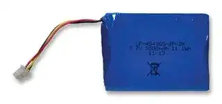
LP-454965-2P-3M
Rechargeable Battery, 3.7 V, Lithium Ion, 3 Ah, Connector, 1
⚠️ Reference pricing provided. In case of supply shortages, we will connect you with our trusted procurement partners to ensure your project's continuity.
- Manufacturer: BAK TECHNOLOGY
- Product type: Batteries - Rechargeable
- Battery Voltage:3.7V; Battery Technology:Lithium Ion; Battery Capacity:3Ah; Battery Size Code:-; Battery Terminals:Connector; External Diameter:-; External Height:9.5mm; External Width:68mm; Exte
- SVHC: No SVHC (17-Dec-2014)
- Weight: 58g
- Pack Quantity: 1
- Product Range: -
- External Depth: 50mm
- External Width: 68mm
- Battery Voltage: 3.7V
- External Height: 9.5mm
- Battery Capacity: 3Ah
- Battery IEC Code: -
- Battery NEDA Code: -
- Battery Size Code: -
- Battery Terminals: Connector
- Battery Compliance: -
- Battery Technology: Lithium Ion
- Battery Type / Size: -
| Delivery and price | |
|---|---|
| Units per pack | 50 |
| Price | 23.94 € |
| Current stock | 10+ |
| Lead time | 30 days |
Datasheet

## **Specification**

## **of**

## **Li-polymer Rechargeable Battery**

## **- - - Model No.: LP 454965 2P 3M**

Reported by: 陈声宇 Date: Oct,28,2013 Checked by: Date: Oct,28,2013 Approved by: Date: Oct,28,2013

## **1. Scope**

This specification describes the definition, technical requirement, testing method, warning and caution of the Lithium ion polymer rechargeable battery.

## **2. Product Model**

Battery type: Rechargeable Lithium-ion Polymer Battery Battery Model: LP-454965-2P-3M

## **3. Ratings**

3.1. Nominal Capacity[at 0.2C]:        2800mAh (min ); 3000mAh (typical ) 3.2. Nominal Voltage:                3.7V (average voltage at 0.2C discharge) 3.3. Charging Voltage:                4.20 ± 0.05V 3.4. Max. Charging Current:           0.5C(1400mA) 3.5. Charging Method: constant current constant voltage Standard Charge:                 0.2(560mA) (constant current) charge to 4.20V, then 4.2V (constant voltage)  for 6~7hrs or 0.02C cut off Quick Charge:                   0.5C(1400mA) (constant current) charge to 4.20V, then 4.2V (constant voltage) for 3.5hr or 0.02C cut off 3.6. Max. Continuous Discharge Current: 2CmA(5600mA) 3.7. Discharge Cut-off Voltage:         2.5V ± 0.062V 3.8. Battery Dimensions (Refer to the attached drawing) 3.9.Cell Weight:                    58 ± 3.0g 3.10. Operating Temperature Discharge:                    -20 ℃ ~ +60 ℃ Charging:                     0 ℃ ~ +45 ℃ Storage in a 50% charged state Temperature range                Duration             Typ. Capacity recovery -20 ℃ - +80 ℃ 10 days                50%(expected) -20 ℃ - +60 ℃ 1month                75%(expected) -20 ℃ - +45 ℃ 3months              70%(expected) -20 ℃ - +25 ℃ 1year                 80%(expected)

## **4. Battery Performance**

## 4.1. Visual Inspection

There shall be no such defects as remarkable scratches, cracks, leakage or deformations.

- 4.2. Test Condition

## 4.2.1.Standard Test Condition

Test new cells within one month after shipment from our factory and the cells shall not be cycled over five times before the tests.

All the tests in this specification shall be conducted in an ambient temperature of 25 ℃

- ± 5 ℃ under a humidity of 25% to 85%, unless otherwise specified.

## 4.2.2 Measuring Instrument or Apparatus

- 4.2.2.1. The dimension measurement shall be implemented by instruments with equal or more precision of 0.01mm.

- 4.2.2.2 Standard class specified in the national standard or more sensitive class having inner

impedance more than 10k Ω /V.

- 4.2.2.3 Impedance shall be measured by a sinusoidal alternating current method (1kHz LCR meter).

- 4.2.2.4 The current measurement shall be implemented by instrument with equal to more precision scale of ± 0.1% and the constant voltage precision should be implemented

with ± 0.5%, and the timing precision should be not below ± 0.1%.

- 4.2.2.5 The temperature measurement shall be implemented by instrument with equal or more precision seal of ± 0.5 ℃ .

- 4.3 Electrical Characteristics

## 4.3.1 Standard Charge

The cell shall be charged at a constant current of 0.2C to 4.2V and then at constant voltage of 4.2V with a charging time of 3.5 hours or 0.02C cut off.

## 4.3.2 Rated Capacity (0.2C):  2800mAh (minimum)

The capacity shall be measured at a discharge current of 0.2C and a cut-off voltage of 2.75V after the standard charge (Section 4.3.1.)

- 4.3.3 High Rate Discharge Capacity (1C):  85% (minimum) of Rated Capacity The capacity shall be measured at a discharge current of 1C and a cut-off voltage of 2.75V after the standard charge (Section 4.3.1.)

- 4.3.4 Low Temperature Discharge Capacity (0 ℃ ):  80% (minimum) of Rated Capacity The capacity shall be measured at a discharge current of 0.2C in an ambient temperature

   - of 0 ℃± 2 ℃ and a cut-off voltage of 2.75V after the standard charge (Section 4.3.1.)

- 4.3.5 Low Temperature Discharge Capacity (-10 ℃ ):  70% (minimum) of Rated Capacity

The capacity shall be measured at a discharge current of 0.2C in an ambient temperature

of -10 ℃± 2 ℃ and a cut-off voltage of 2.75V after the standard charge (Section 4.3.1.)

## 4.3.6 High Temperature Discharge Capacity (60 ℃ ):  100% (minimum) of Rated Capacity

The capacity shall be measured at a discharge current of 0.2C in an ambient temperature of 60 ℃± 2 ℃ and a cut-off voltage of 2.75V after the standard charge (Section 4.3.1.)

## 4.3.7. Storage Characteristics (25 ℃ )

Capacity Retention:  85% (minimum) of Rated Capacity Capacity Recovery:  90% (minimum) of Rated Capacity

The capacity retention shall be measured at a discharge current of 0.2C and a cut-off voltage of 2.75V after standard charge (Section 4.3.1.) and being stored for 28 days

at 25 ℃± 5 ℃ . Then, the capacity recovery shall be measured at a discharge current of

0.2C and a cut-off voltage of 2.75V after standard charge (Section 4.3.1.).

## 4.3.8. Storage Characteristics   (45 ℃ )

Capacity Retention:  60% (minimum) of Rated Capacity Capacity Recovery:  70% (minimum) of Rated Capacity

The capacity retention shall be measured at a discharge current of 0.2C and a cut-off voltage of 2.75V after standard charge (Section 4.3.1.) and being stored for 28 days at

45 ℃± 5 ℃ . Then, the capacity recovery shall be measured at a discharge current

Of 0.2C and a cut-off voltage of 2.75V after standard charge (Section 4.3.1.)

## 4.3.9 Internal Impedance:  70m Ω (Type) ;  90m Ω (max)

The internal impedance shall be measured at a since wave alternative current process of 1kHz after the standard charge.

## 4.3.10. Cycle Life :

The cycle life shall be conducted as the following procedures :

Step 1: charge the cell with the standard charge (as of section 4.3.1); Step 2: discharge the cell at 0.5C to 2.75V,

Step 3: repeat Step 1 and Step 2 for 500 times.

The capacity after 300 cycles is expected to be equal to or more than 80% of the rated

capacity. The capacity after 500 cycles is expected to be equal to or more than 60% of the rated capacity.

- 4.3.11 Open Circuit Voltage: 3.6V ~ 4.1V as of shipment.

- 4.4 Mechanical Performance

- 4.4.1 Vibration Test: 95% (min) of Rated Capacity, No Leakage

After standard charge (Section 4.3.1.), the battery is vibrated with an amplitude of 0.8mm

(1. 6mm total maximum excursion) for 60 minutes in three mutually perpendicular directions. The vibration is performed between 10Hz and 55Hz at a rate of 1Hz per minute After the completion of the vibration, the capacity shall be measured at a discharge current

of 0.2C and a cut-off voltage of 2.75V

- 4.5 Environmental Performance

- 4.5.1 Thermal Shock Test:  No Leakage, No Fire, No Explosion

The battery is stored at 75 ℃± 5 ℃ for 48 hours, moved to a temperature of -20 ℃± 5 ℃

within 5 minutes and stored for 6 hours after standard charge (Section 4.3.1.).

- 4.6 Safety Performance

- 4.6.1 Short Circuit Test:  No Fire, No Explosion

After standard charge (Section 4.3.1.), the battery shall be subjected to a short-circuit

condition with a wire of resistance less than50m Ω for 1 hour.

- 4.6.2 Overcharge Test:  (with a PCM) No Fire, No Explosion After standard charge (Section 4.3.1.), the battery shall be charged at 1C /12V For 2.5 hrs.

- 4.6.3 Thermal Exposure Test  No Fire, No Explosion

After standard charge (Section 4.3.1.), the battery is placed in an oven and is heated up at a

rate of 5 ℃ until the temperature reaches 130 ℃ . The oven shall be maintained at 130 ℃ for 60 minutes.

## **5. Delivery Condition:** about 50% charged.

## **6. Lithium Ion Polymer Battery Handling Guideline**

- 6.1 In case of contacting the materials from a damaged or ruptured cell or battery:

Eye contact: Washing immediately with plenty of water and soap or for at least 15 minutes.

Get medical attention.

Skin Contact: Washing immediately with water and soap. Inhalation of Vented Gas:

Remove to fresh air. Get medical attention. Ingestion: Get medical attention immediately.

- 6.2 Keep away batteries from children.

- 6.3 The cells/ batteries are requested to be stored within a proper temperature range specified in this specification.

- 6.4 Do not store batteries in a manner that allow s terminals to short circuit.

- 6.5 Do not place batteries near heating sources, nor exposed to direct sunlight for long periods. Elevated temperatures can result in reduced battery service life.

- 6.6 Charging Battery

Use only approved chargers and procedures. Improperly charging a cell or battery may cause the cell or battery to flame or damage.

Charge the battery using the “CC/CV” or constant current /constant voltage method.

Do not charge the battery with a current or voltage higher than the specified maximum value in this specification. The absolute maximum charging voltage is 4.25V per cell.

Prohibit reverse charging of the battery. The battery must be connected correctly.

- 6.7 Discharging Battery

Discharge battery at the max current specified in this specification. If you plan to discharge battery at a higher current than the max current, please consult us.

Avoid discharge the battery below 2.75V for each cell.

Do not over-discharge the battery. Over-discharging can damage the performance of the battery. It should be noted that the cell/battery would be at an over-discharged state by its self-discharge characteristics in case the cell is not used for long time. In order to prevent over-discharging, the cell/battery shall be charged periodically to maintain between 3.7V and 4.1V.

## 6.8 Operation Temperature

The battery shall be operated (stored, charged and discharged) in the temperature specified in This specification.

## 6.9 Cell/Battery Protection Circuit Module (PCM)

The cell/battery must be equipped with a PCM that protects the cell/battery from overcharging, over-discharging and over-current.

- 6.10 Battery Short Circuit

Do not short-circuit a battery. A short circuit can result in over-heating of the terminals and provide an ignition source. More than a momentary short circuit will generally reduce the cell or battery service life and can lead to ignition of surrounding materials or materials within the cell or battery if the seal integrity is damaged. Extended short-circuiting creates high temperature in the cell and at the terminals. Physical contact to high temperatures can cause skin burns. In addition, extended short-circuit may cause the cell or battery to flame.

- 6.11 Prohibit reversing cell polarity within a battery assembly.

- 6.12 The cell edge of the heat seal zone is electrically conductive. Avoid the edge cross battery terminals, PCB, or conductive surfaces.

- 6.13 Do not bend, fold or fall the battery or part of the battery. It may cause the battery be damaged and result in the battery swelling, leaking, explosion or ignition

- 6.14 Do not open or manipulate the folded cell edge.

- 6.15 Do not bend or fold the sealing edge. And do not tear off the sealing film.

- 6.16 Battery Pack Design

The battery housing should have sufficient mechanical strength.

No sharp edge components shall be inside the battery housing. The sharp edge may destroy the cell packaging.

No cell movement is allowed in the battery housing.

The ultrasonic head shall not directly/ or indirectly pressed the cell if you need to enclose the battery housing by ultrasonic method. Please consult us for designing the ultrasonic head. Avoid designing airtight battery housing.

- 6.17 Battery Assembly

We recommend ultrasonic welding or spot welding to connect battery with PCM or other parts. If you employ manual solder method to connect tab with PCM, please pay attention to the followings:

Use a solder with temperature controlled and ESD.

Soldering temperature should not exceed 300 ℃ .

Soldering time should not be longer than 3s.

Soldering times should not exceed 5 times.

Keep battery tab cold down before next time soldering.

Do not directly heat cell body. It may cause the battery be damaged by heat above 90 ℃

## 6.18 Battery Disassembly

Never disassemble a battery.

Should a battery unintentionally be crushed, thus releasing its contents, rubber gloves must

be used to handle all battery components. Avoid inhalation of any vapors that may be emitted.

- 6.19 Do not mixed Batteries and Types. Avoid to use old and new cells or cells of different sizes, different chemistry or types in the same battery assembly.

## 6.20 Other Warnings

Do not heat or dispose the battery into fire, water or other liquids.

Do not put the battery into microwave, washing machine or drying machine. Do not use a damaged battery.

## 6.21 Others

## **7. Remarks**

If any matter with this specification arises, it shall be revised by mutual agreements.

## **8. Drawing for battery pack:**

## **Data sheet for protect circuit board**

## **1. Electrical Characteristics (for RicohR5402N245KD )(T=25oC )**

The followings is referring to the specs of R5402N245KD of Ricoh (for details, see R5402N245KD specs). These specs are guaranteed by design not by production tests.

- 1.1 Input Voltage: 1.5V (min) 5.0V(max)

- 1.2 Overcharge Detection : 4.225V (min) 4.250(Typ) 4.275V(max)

- 1.3 Output Delay of Overcharge: 0.7s (min) 1.0s(Typ.) 1.3s (max)

- 1.4 Overcharge Release : 3.90V (min) 3.95V(Typ) 4.00V(max)

- 1.5 Over-discharge Detection : 2.438V (min) 2.500V(Typ) 2.562V(max)

1.6 Output Delay of Over-discharge: 14ms (min) 20ms(Typ.) 26ms (max)

1.7 Over-discharge Release 2.925 (min) 3.000V(Typ) 3.075V(max)

1.8 Over Discharge-Current Detection : 0.185V (min) 0.20V(Typ) 0.215V(max)

1.9 Over charge-Current Detection : 0.215V (min) 0.20V(Typ) 0.215V(max)

1.10 Over Discharge-Current Value: 12A(min) 14A(Typ) 16A (max)

1.11 Over charge-Current Value: A(min) A(Typ) A (max)

1.12 Output Delay of Over-Discharge-Current: 8ms (min) 12ms(Typ.) 16ms (max)

1.13 Short Protection Voltage: 0.55V (min) 0.8 V (Typ) 1.0V (max)

1.14 Output Delay of Short Protection: 230μs (Min) 300 μs(Typ.) 500 μs(max)

1.15 Supply Current (active status): μA (Min) 4μA (Typ.) 8μA (max)

1.16 Supply Current (Standby): 1.2μA (Typ.) 2μA (max)

1.17 PCMResistance : 10mΩ (Min) 20mΩ (Typ.) 30mΩ (max)

## **2. Part List**

## **3. PCM Circuit Diagram**

**==> picture [75 x 12] intentionally omitted <==**

**----- Start of picture text -----**<br>
4. PCB layout<br>**----- End of picture text -----**<br>
Updated at June 4, 2026
About Novapart
Novapart is a B2B electronic component broker specialising in stock shortages and cost reduction. We source hard-to-find parts and identify compliant alternatives across a catalogue of 410,000+ components from 500+ manufacturers.
Learn more →Stock Shortage Specialist
When a component is unavailable, discontinued or has an unacceptable lead time, we tap into our network of vetted European and Asian distributors to source what you need — without compromising on quality or traceability.
Request a quote →Compliant Alternatives
We identify pin-to-pin, electrically equivalent substitutes that meet the same certifications (RoHS, AEC-Q100, REACH) as your original specification — validated against datasheets, not just part numbers. Often at a lower cost.
BOM Analysis service →