
Image not available
Illustrative purposes only

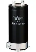
LNC2V682MSEG
ALUMINUM ELECTROLYTIC CAPACITOR, 6800UF, 350V, 20%, SCREW
⚠️ Reference pricing provided. In case of supply shortages, we will connect you with our trusted procurement partners to ensure your project's continuity.
- Manufacturer: NICHICON
- Product type: Snap In / Screw Terminal Aluminium Electrolytic Capacitors
- Polarity: Polar
- Capacitance: 6800µF
- Voltage(DC): 350V
- Lead Spacing: 28.6mm
- Product Range: NC Series
- Product Height: 135mm
- Ripple Current: 20.3A
- Product Diameter: 63.5mm
- Capacitor Terminals: Screw
- Capacitance Tolerance: ± 20%
- Lifetime @ Temperature: 500 hours @ 85°C
- Operating Temperature Max: 85°C
- Operating Temperature Min: -40°C
| Delivery and price | |
|---|---|
| Units per pack | 25 |
| Price | 57.42 € |
| Current stock | 10+ |
| Lead time | 30 days |
Datasheet

**ALUMINUM  ELECTROLYTIC  CAPACITORS**

## **LNC**

Screw Terminal Type, 85°C Smaller-sized Higher ripple current

Suited for use in industrial power supplies for inverter circuritry, etc.

Load life 5000 hours application of ripple current at 85°C.

e Smaller sized / High ripple current than LNX, LNK. e Coped with loading of high speed charge-discharge. e Suited for high frequency regenerative voltage for AC servomotor, general inverter.

Compliant to the RoHS directive (2011/65/EU).

High speed charge-discharge

## **LQR**

**==> picture [44 x 26] intentionally omitted <==**

**----- Start of picture text -----**<br>
LNX LNK<br>Smaller<br>High ripple<br>**----- End of picture text -----**<br>


## **LNC**

## Specifications

Item Performance Characteristics ~~PT~~ Category Temperature Range – 40 to +85°C ~~a~~ Rated Voltage  Range 350 to 500V ~~|~~ Rated Capacitance Range 1000 to 22000µF ~~a~~ Capacitance Tolerance ± 20%  at 120Hz, 20°C Leakage Current After 5 minutes' application of rated voltage, leakage current is not more than             ([C:Rated Capacitance(µF),  V:Voltage(V)] 3 CV µA) or 5 mA, whichever is smaller (at 20°C). ~~esa~~ Tangent of loss angle (tan δ) 0.20MAX.  (120Hz at 20°C) Rated voltage (V) 350 to 500 Measurement frequency : 120Hz Stability at Low Temperature Z – 40°C / Z+20°C Impedance ratio ZT/Z20(MAX.) 8 ~~a~~ Insulation Resistance The insulation resistance shall be more than 100MΩ at DC 500V application between terminal and bracket. ~~Pt~~ Voltage proof There is no abnormality during AC 2500V 1 minute's application between terminal and bracket. The specifications listed at right shall be met when the capacitors are restored Capacitance change Within ± 20% of the initial capacitance value Endurance to 20°C after D.C. bias plus rated ripple current is applied for 5000 hours at tan δ 200% or less than the initial specified value 85°C, the peak voltage shall not exceed the rated voltage. Leakage current Less than or equal to the initial specified value After storing the capacitors under no load at 85°C for 1000 hours and Capacitance change Within ±20% of the initial capacitance value Shelf Life then performing voltage treatment based on JIS C 5101-4 clause 4.1 tan δ 200% or less than the initial specified value at 20°C, they shall meet the reguirements listed at right. Leakage current Less than or equal to the initial specified value Endurance of chargeAfter an application of charge-discharge voltage for 50million times Capacitance change Within ±20% of the initial capacitance value discharge behavior (charge-discharge voltage difference(3Hz)capacitors shall meet the characteristics requirement listed at right.ΔV)=rated voltage × 0.3, cycle tan Leakage currentδ 200% or less than the initial sLess than or equal to the initial specified valuepecified value ~~|~~ Marking Printed with white color letter on black sleeve.

**==> picture [511 x 203] intentionally omitted <==**

**----- Start of picture text -----**<br>
a Drawing<br>Bottom plate Hexagenal headed bolt Type numbering system (Example : 400V  10000µF)<br>Sleeve<br>1 2 3 4 5 6 7 8 9 10 11 12 13 14<br>Pressure relief vent<br>L N C 2 G 1 0 3 M S E H<br>Le Sa) CoO O00<br>al: | 4 (51 to § 90) Mounting bracket<br>h P [±2]<br>| K B A [±2] i_,eKSa Capacitance toleranceConfiguration (+20%) odeCode less ess | StdStud  mountmount  typ5|ype<br>H [±1]<br>i Ys Rated capacitance (10000uF)<br>L [+    MAX.] a n ±1 Rated voltage (400V)<br>U Series name<br>S<br>B<br>* hi Type<br>3-leg brackets for φ90 capacitors have different mic)<br>hole shapes from the ordinary ones illustrated<br>Configuration<br>below. P SE standard specifications<br>—— '@7 oe TE stud mount type<br> Please refer to page 324 for schematic of dimensions.<br>Please contact to us if PVC less products are required.<br>7<br>Pressure relief vent<br>Note) The brackets will be supplied in the separate box. 30°<br>120°<br>T<br>U<br>S<br>±1W +2MAX.D<br>T<br>P ±2A<br>5<br>**----- End of picture text -----**<br>


|About product of stud bolt<br>Nylon nut and nylon washer attachment become the standard<br>specifications. (cf. P.324)<br>φD<br>51<br>63.5<br>76.2<br>90<br>W<br>22.0<br>28.6<br>31.8<br>31.8<br>R<br>6<br>6<br>6<br>6<br>α<br>3<br>3<br>3<br>3<br>Nominal dia. of bolt<br>M 5<br>M 5<br>M 5<br>M 5<br>(mm)<br>Dimension of terminal pitch (W)  and length (R)  and Nominal dia.of bolt|Nominal dia. of bolt<br>(mm)|(mm)<br>Dimensions of mounting bracket<br>(mm)<br>51<br>63.5<br>76.2<br>90<br>33.2<br>40.5<br>46.5<br>53<br>40<br>46.5<br>53<br>59<br>6.0<br>7.0<br>6.0<br>6.0<br>4.5<br>4.5<br>4.5<br>4.5<br>14<br>14<br>14<br>14<br>30<br>30<br>30<br>30<br>25<br>35<br>35<br>35<br>15<br>20<br>20<br>20<br>P<br>H<br>h<br>A<br>T<br>S<br>U<br>°<br>51<br>63.5<br>76.2<br>90<br>32.5<br>38.1<br>44.5<br>50.8<br>38.5<br>43<br>49.2<br>58.5<br>7.5<br>8.0<br>7.0<br>8.0<br>5.0<br>5.0<br>5.0<br>5.0<br>12<br>14<br>14<br>18<br>60<br>60<br>60<br>60<br>20<br>25<br>30<br>35<br>15<br>20<br>24<br>25<br>2--Leg<br>Symbol<br>Leg shape<br>φD<br>3--Leg<br>e~~Be~~<br>~~PSS~~<br>~~ee~~<br>~~po~~<br>~~po~~<br>~~po~~<br>~~po~~<br>~~po~~<br>~~poe OT~~<br>~~po~~<br>~~a~~<br>~~GG~~|
|---|---|---|


About product of stud bolt Nylon nut and nylon washer attachment become the standard specifications. (cf. P.324) It is not attached to the bracket. Field 13 and 14 become blank in Type number system.

Dimension table in next page.

CAT.8100E

334

**ALUMINUM  ELECTROLYTIC  CAPACITORS**

## **LNC**

Dimensions

||350V(2V)|350V(2V)|350V(2V)|350V(2V)|350V(2V)|
|---|---|---|---|---|---|
|Cap.<br>(µF)|Size<br>φD×L(mm)|Rated ripple<br>(Arms)|tanδ|Leakage Current<br>(mA)|Code|
|1000|51×55|8.4|0.20|1.77|LNC2V102MSEF|
|1200|51×60|8.6|0.20|1.94|LNC2V122MSEF|
|1500|51×65|9.3|0.20|2.17|LNC2V152MSEF|
|1800|51×75|10.3|0.20|2.38|LNC2V182MSEF|
|2200|51×85|11.9|0.20|2.63|LNC2V222MSEF|
|2700|51×95|13.3|0.20|2.92|LNC2V272MSEF|
||63.5×70|13.7|0.20|2.92|LNC2V272MSEG|
|3300|51×115|13.6|0.20|3.22|LNC2V332MSEF|
||63.5×80|14.0|0.20|3.22|LNC2V332MSEG|
|3900|63.5×85|14.9|0.20|3.50|LNC2V392MSEG|
||76.2×70|14.3|0.20|3.50|LNC2V392MSEH|
|4700|63.5×100|16.4|0.20|3.85|LNC2V472MSEG|
||76.2×80|15.7|0.20|3.85|LNC2V472MSEH|
|5600|63.5×115|18.1|0.20|4.20|LNC2V562MSEG|
||76.2×90|17.6|0.20|4.20|LNC2V562MSEH|
|6800|63.5×135|20.3|0.20|4.63|LNC2V682MSEG|
||76.2×100|19.7|0.20|4.63|LNC2V682MSEH|
|8200|76.2×115|22.2|0.20|5.00|LNC2V822MSEH|
||90×90|24.2|0.20|5.00|LNC2V822MSEJ|
|10000|76.2×135|25.2|0.20|5.00|LNC2V103MSEH|
||90×100|27.1|0.20|5.00|LNC2V103MSEJ|
|12000|76.2×155|28.2|0.20|5.00|LNC2V123MSEH|
||90×120|30.1|0.20|5.00|LNC2V123MSEJ|
|15000|90×145|35.4|0.20|5.00|LNC2V153MSEJ|
|18000|90×165|39.2|0.20|5.00|LNC2V183MSEJ|
|22000|90×205|43.4|0.20|5.00|LNC2V223MSEJ|


||450V(2W)|450V(2W)|450V(2W)|450V(2W)|450V(2W)|
|---|---|---|---|---|---|
|Cap.<br>(µF)|Size<br>φD×L(mm)|Rated ripple<br>(Arms)|tanδ|Leakage Current<br>(mA)|Code|
|1000|51×70|9.3|0.20|2.01|LNC2W102MSEF|
|1200|51×80|9.9|0.20|2.20|LNC2W122MSEF|
|1500|51×90|10.4|0.20|2.46|LNC2W152MSEF|
|1800|51×105|11.5|0.20|2.70|LNC2W182MSEF|
||63.5×70|11.9|0.20|2.70|LNC2W182MSEG|
|2200|63.5×85|12.3|0.20|2.98|LNC2W222MSEG|
||76.2×65|12.5|0.20|2.98|LNC2W222MSEH|
|2700|63.5×90|13.7|0.20|3.31|LNC2W272MSEG|
||76.2×75|13.7|0.20|3.31|LNC2W272MSEH|
|3300|63.5×115|15.6|0.20|3.66|LNC2W332MSEG|
||76.2×85|15.5|0.20|3.66|LNC2W332MSEH|
|3900|63.5×135|17.3|0.20|3.97|LNC2W392MSEG|
||76.2×90|17.0|0.20|3.97|LNC2W392MSEH|
|4700|63.5×145|19.2|0.20|4.36|LNC2W472MSEG|
||76.2×115|19.2|0.20|4.36|LNC2W472MSEH|
|5600|63.5×165|21.4|0.20|4.76|LNC2W562MSEG|
||76.2×135|21.6|0.20|4.76|LNC2W562MSEH|
||90×95|24.2|0.20|4.76|LNC2W562MSEJ|
|6800|76.2×145|23.8|0.20|5.00|LNC2W682MSEH|
||90×115|27.5|0.20|5.00|LNC2W682MSEJ|
|8200|76.2×185|27.2|0.20|5.00|LNC2W822MSEH|
||90×135|30.5|0.20|5.00|LNC2W822MSEJ|
|10000|90×155|34.1|0.20|5.00|LNC2W103MSEJ|
|12000|90×185|38.2|0.20|5.00|LNC2W123MSEJ|
|15000|90×215|43.1|0.20|5.00|LNC2W153MSEJ|


||400V(2G)|400V(2G)|400V(2G)|400V(2G)|400V(2G)|
|---|---|---|---|---|---|
|Cap.<br>(µF)|Size<br>φD×L(mm)|Rated ripple<br>(Arms)|tanδ|Leakage Current<br>(mA)|Code|
|1000|51×60|8.6|0.20|1.90|LNC2G102MSEF|
|1200|51×65|9.3|0.20|2.08|LNC2G122MSEF|
|1500|51×80|10.8|0.20|2.32|LNC2G152MSEF|
|1800|51×85|12.0|0.20|2.55|LNC2G182MSEF|
|2200|51×100|13.0|0.20|2.81|LNC2G222MSEF|
||63.5×70|12.8|0.20|2.81|LNC2G222MSEG|
|2700|63.5×80|14.5|0.20|3.12|LNC2G272MSEG|
||76.2×65|14.3|0.20|3.12|LNC2G272MSEH|
|3300|63.5×90|14.9|0.20|3.45|LNC2G332MSEG|
||76.2×70|15.3|0.20|3.45|LNC2G332MSEH|
|3900|63.5×100|16.5|0.20|3.75|LNC2G392MSEG|
||76.2×80|17.1|0.20|3.75|LNC2G392MSEH|
|4700|63.5×120|18.8|0.20|4.11|LNC2G472MSEG|
||76.2×90|18.3|0.20|4.11|LNC2G472MSEH|
|5600|63.5×135|20.9|0.20|4.49|LNC2G562MSEG|
||76.2×100|20.2|0.20|4.49|LNC2G562MSEH|
|6800|63.5×165|23.8|0.20|4.95|LNC2G682MSEG|
||76.2×120|23.1|0.20|4.95|LNC2G682MSEH|
||90×90|26.3|0.20|4.95|LNC2G682MSEJ|
|8200|76.2×145|26.1|0.20|5.00|LNC2G822MSEH|
||90×105|29.5|0.20|5.00|LNC2G822MSEJ|
|10000|76.2×165|29.5|0.20|5.00|LNC2G103MSEH|
||90×120|33.2|0.20|5.00|LNC2G103MSEJ|
|12000|90×145|37.1|0.20|5.00|LNC2G123MSEJ|
|15000|90×185|42.9|0.20|5.00|LNC2G153MSEJ|
|18000|90×205|48.2|0.20|5.00|LNC2G183MSEJ|


|500V(2H)|500V(2H)|500V(2H)|500V(2H)|500V(2H)|500V(2H)|
|---|---|---|---|---|---|
|Cap.<br>(µF)|Size<br>φD×L(mm)|Rated ripple<br>(Arms)|tanδ|Leakage Current<br>(mA)|Code|
|1000|51×85|10.3|0.20|2.12|LNC2H102MSEF|
|1200|63.5×70|10.4|0.20|2.32|LNC2H122MSEG|
|1500|63.5×80|11.6|0.20|2.60|LNC2H152MSEG|
|1800|63.5×90|12.7|0.20|2.85|LNC2H182MSEG|
|2200|63.5×100|14.2|0.20|3.15|LNC2H222MSEG|
|2700|76.2×90|15.8|0.20|3.49|LNC2H272MSEH|
|3300|76.2×10⁵|17.8|0.20|3.85|LNC2H332MSEH|
|3900|76.2×120|19.9|0.20|4.19|LNC2H392MSEH|
|4700|90×105|23.6|0.20|4.60|LNC2H472MSEJ|
|5600|90×120|26.4|0.20|5.00|LNC2H562MSEJ|
|6800|90×145|30.0|0.20|5.00|LNC2H682MSEJ|
|8200|90×165|33.7|0.20|5.00|LNC2H822MSEJ|
|10000|90×205|38.3|0.20|5.00|LNC2H103MSEJ|


Rated ripple current (Arms) at 85°C 120Hz

## Frequency coefficient of rated ripple current

|50|60|120|360|1k|10k or more|
|---|---|---|---|---|---|
|0.80|0.82|1.00|1.20|1.35|1.40|


CAT.8100E

335
Updated at February 9, 2023
About Novapart
Novapart is a B2B electronic component broker specialising in stock shortages and cost reduction. We source hard-to-find parts and identify compliant alternatives across a catalogue of 410,000+ components from 500+ manufacturers.
Learn more →Stock Shortage Specialist
When a component is unavailable, discontinued or has an unacceptable lead time, we tap into our network of vetted European and Asian distributors to source what you need — without compromising on quality or traceability.
Request a quote →Compliant Alternatives
We identify pin-to-pin, electrically equivalent substitutes that meet the same certifications (RoHS, AEC-Q100, REACH) as your original specification — validated against datasheets, not just part numbers. Often at a lower cost.
BOM Analysis service →