
Image not available
Illustrative purposes only

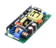
LHP150F-42-Y
AC/DC Open Frame Power Supply (PSU), ITE, 1 Output, 151.2 W, 85V AC to 264V AC, Fixed
⚠️ Reference pricing provided. In case of supply shortages, we will connect you with our trusted procurement partners to ensure your project's continuity.
- Manufacturer: COSEL
- Product type: AC / DC Open Frame Power Supplies
- SVHC: No SVHC (23-Jan-2024)
- Product Range: LHP Series
- No. of Outputs: 1 Output
- Input Voltage VAC: 85V AC to 264V AC
- Power Supply Output Type: Fixed
- Output Current - Output 1: 3.6A
- Output Current - Output 2: -
- Output Current - Output 3: -
- Output Current - Output 4: -
- Output Voltage - Output 1: 42V
- Output Voltage - Output 2: -
- Output Voltage - Output 3: -
- Output Voltage - Output 4: -
- Power Supply Applications: ITE
- Power Rating (Forced Cooling): -
- Power Rating (Convection Cooling): 151.2W
| Delivery and price | |
|---|---|
| Units per pack | 30 |
| Price | 79.25 € |
| Current stock | 10+ |
| Lead time | 30 days |
Datasheet

**AC-DC Power Supplies Open Frame** = 3 4 > > Power World wide Safety EMI Inrush OCP OVP Cost Rugged Factor Approvals current Effective PCB type Correction limiting

## **LHP-series**

## ~~ao~~ **Feature CE marking**

OVC III

Low Voltage Directive RoHS Directive

High power & high peak power High efficiency Low profile Active Power factor correction Harmonic attenuator (Complies with IEC61000-3-2) Universal input (85 - 264 VAC) Built-in inrush current, over current, over voltage protection

## **UKCA marking**

## a

Electrical Equipment Safety Regulations RoHS Regulations

## **EMI**

## ~~a~~ **EMI**

## **Safety agency approvals**

**Safety agency approvals** Complies with FCC-B, CISPR11-B, CISPR32-B, EN55011-B, EN55032-B, VCCI-B UL62368-1, C-UL (equivalent to CAN/CSA-C22.2 No.62368-1), EN62368-1 ~~aa~~ EN62477-1 (OVC III) **EMS Compliance** : EN61204-3, EN61000-6-2 Complies with DEN-AN EN61000-4-2 UL508 (Optional) EN61000-4-3

EN61000-4-2 EN61000-4-3 EN61000-4-4 EN61000-4-5 EN61000-4-6 EN61000-4-8 EN61000-4-11

## ~~a~~ **5-year warranty (refer to Instruction Manual)**

**LHP-1**

www.cosel.co.jp/en/

April 19, 2023

**AC-DC Power Supplies Open Frame**

**LH P 150 F** OO **-** O

## **Ordering information**

## **LHP150F**

1 2 3 4 5 6

1Series name

**==> picture [499 x 100] intentionally omitted <==**

**----- Start of picture text -----**<br>
R R Example recommended EMI/EMC filterEAC-03-472 2Single output<br>3Output wattage<br>cis (D) 2  C € ca eeLe . e. 4Universal input<br>ea hae 4 <A 5Output voltage<br>6Optional  [*][1]<br>C : with Coating<br>ne gh ' f  G: Low leakage current<br>J4 : EP(TE Connectivity) connector type<br>4 Seeereneees deg + ie High voltage pulse noise type : EAP seriesLow leakage current type : EAM series R S : with ChassisO : with Remote ON/OFF S : with ChassisO : with Remote ON/OFFO : with Remote ON/OFF : with Remote ON/OFF<br>*A higher current rating EMI/EMC filter may be recommended in view of the  SN : with Chassis & cover : with Chassis & cover<br>other devices that could be connected   T : Terminal block type<br>in parallel with the power supply. T4 : Push-in Terminal Block Type : Push-in Terminal Block TypePush-in Terminal Block Type<br>**----- End of picture text -----**<br>


R S : with ChassisO : with Remote ON/OFF S : with ChassisO : with Remote ON/OFFO : with Remote ON/OFF : with Remote ON/OFF SN : with Chassis & cover : with Chassis & cover T : Terminal block type T4 : Push-in Terminal Block Type : Push-in Terminal Block TypePush-in Terminal Block Type T5 : UL508

U1 : Can be attached the external capacitor unit For option details, refer to instruction manual 7.1.

This power supply is manufactured by SMD technology. The stress to PCB like twisting or bending causes the defect of the unit, so handle the unit with care.

*Make sure necessary tests will be carried out on your end equipment with the power supply installed in accordance with any required EMC/EMI regulations.

|**MODEL**|**LHP150F-24-Y**|**LHP150F-30-Y**|**LHP150F-36-Y**|**LHP150F-42-Y**|**LHP150F-48-Y**|
|---|---|---|---|---|---|
|**MAXOUTPUT WATTAGE[W]**<br>*2|**151.2(302.4)**|**150.0 (300.0)**|**151.2(302.4)**|**151.2(302.4)**|**153.6 (307.2)**|
|**DC OUTPUT**<br>*2|**24V6.3A (12.6A)**|**30V5.0A (10.0A)**|**36V4.2A(8.4A)**|**42V3.6A (7.2A)**|**48V3.2A(6.4A)**|


||**MODEL**<br>~~ee~~|**MODEL**<br>~~ee~~|**LHP150F-24-Y**<br>~~ee~~|**LHP150F-30-Y**<br>~~ee~~|**LHP150F-36-Y**<br>~~ee~~|**LHP150F-42-Y**<br>~~ee~~|**LHP150F-48-Y**|
|---|---|---|---|---|---|---|---|
|**INPUT**<br>~~[|~~|**VOLTAGE[VAC]**<br>~~Po~~||85- 264 1f (Refer to“Derating”andInstruction Manual 1.1) *8|||||
||**CURRENT[A]**<br>~~—~~|**ACIN 100V**<br>~~—~~|1.80typ|||||
|||**ACIN 230V**<br>~~—~~<br>~~[|~~|0.80typ|||||
||**FREQUENCY[Hz]**<br>~~Po~~<br>~~a~~||50 / 60 (45-66)<br>~~a~~<br>~~ee~~|||||
||**EFFICIENCY[%]**<br>~~a~~<br>~~—~~|**ACIN 100V**<br>~~a~~|90.0typ<br>~~a~~|90.0typ|90.5typ<br>~~ee~~|90.5typ<br>~~ee~~|91.0typ|
|||**ACIN 230V**<br>~~a~~<br>~~—~~|92.0typ<br>~~a~~<br>~~—~~|92.0typ<br>~~a~~|92.5typ<br>~~ee~~|92.5typ<br>~~ee~~|93.0typ|
||**POWER FACTOR (Io=100%)**<br>~~a~~<br>~~—~~|**ACIN 100V**<br>~~a~~<br>~~—~~|0.99typ<br>~~a~~<br>~~ee~~<br>~~a~~<br>~~—~~|||||
|||**ACIN 230V**<br>~~—~~<br>~~|~~|0.93typ<br>~~a~~<br>~~—~~<br>~~|~~|||||
||**INRUSH CURRENT[A]**<br>*3<br>~~=~~<br>~~|~~<br>~~[|~~|**ACIN 100V**<br>~~=~~<br>~~|~~|15typ (Io=100%)Ta=25Catcold start|||||
|||**ACIN 230V**<br>~~=~~<br>~~|~~|35typ (Io=100%)Ta=25Catcold start|||||
||**LEAKAGE CURRENT[mA]**<br>~~|~~<br>~~[|~~<br>C—“‘CS:*sSCSCsCY||0.40/0.75max(ACIN 100 /240V, 60Hz,Io=100%,AccordingtoIEC62368-1, andDEN-AN)|||||
|**OUTPUT**<br>~~[|~~|**VOLTAGE[V]**<br>~~|~~<br>~~[|~~<br>~~es~~||24<br>~~es~~|30<br>~~es~~|36<br>~~es~~|42<br>~~es~~|48|
||**CURRENT[A]**<br>*2*8<br>~~es~~||6.3 (Peak 12.6)<br>~~es~~|5.0 (Peak 10.0)<br>~~es~~|4.2(Peak8.4)<br>~~es~~<br>~~((~~|3.6 (Peak 7.2)<br>~~es~~<br>~~((~~|3.2(Peak6.4)|
||**LINE REGULATION[mV]**<br>*4<br>~~a~~||96max|120max|144max|168max|192max|
||**LOAD REGULATION[mV]**<br>*4<br>~~a~~||150max|150max|180max|210max|240max|
||**RIPPLE[mVp-p]**<br>*5<br>~~a ~~|**0 to +50**C <br> ~~a~~|250max|280max|280max|280max|280max|
|||**-10 to 0**C <br>~~a~~|310max|330max|330max|330max|330max|
|||**Io=0 to 10%** <br>~~a~~|310max|330max|330max|330max|330max|
||**RIPPLE NOISE[mVp-p]**<br>*5<br>~~ae~~|**0 to +50**C <br>~~a~~|290max|310max|310max|310max|310max|
|||**-10 to 0**C <br>~~a ~~|330max<br> ~~a~~|360max|360max|360max|360max|
|||**Io=0 to 10%** <br>~~**a**~~<br>~~ee ee~~|330max<br>~~ee~~|360max|360max|360max|360max|
||**TEMPERATURE REGULATION[mV]**<br>~~ae~~|**0 to +50**C <br>~~**a**~~<br>~~ee ee~~|240max<br>~~ee~~|300max|360max|420max|480max|
|||**-10 to +50**C <br>~~**a**~~<br>~~ee ee~~|290max<br>~~ee~~|370max|450max|530max|600max|
||**DRIFT[mV]**<br>*6<br>~~**a**~~<br>~~ae ee ee~~<br>~~a~~||96max<br>~~ee~~|120max|144max|168max|192max|
||**START-UP TIME[ms]**<br>~~Po~~||70typ (ACIN 100V,Io=100%)|||||
||**HOLD-UP TIME[ms]**<br>~~Po~~||20typ (ACIN 100V,Io=100%)|||||
||**OUTPUT VOLTAGE ADJUSTMENT RANGE[V]**<br>~~a~~||22.80to26.40|28.50to 33.00|34.20 to 39.60|39.90 to 46.20|45.60 to 52.80|
||**OUTPUT VOLTAGE SETTING[V]**<br>~~a~~||24.00to24.96<br>~~GO~~|30.00to 31.20<br>~~GO~~|36.00to 37.44<br>~~GO~~|42.00to43.68<br>~~GO~~|48.00to49.92|
|**PROTECTION**<br>**CIRCUIT AND**<br>**OTHERS**|**OVERCURRENT PROTECTION**<br>~~Po~~||Works over 101% of rating andrecovers automatically|||||
||**OVERVOLTAGE PROTECTION[V]**<br>~~a~~||27.6to 33.6|34.5to42.0|41.4 to 50.4|48.3to 58.8|55.2 to 67.2|
||**OPERATING INDICATION**<br>~~Po~~||Notprovided|||||
||**REMOTESENSING**<br>~~Po~~||Notprovided|||||
||**REMOTEON/OFF(-R**O**)**<br>~~PO~~||Option(Refer toInstruction Manual 7.1)|||||
|**ISOLATION**<br>~~[|~~|**INPUT-OUTPUT**-**RC**<br>*7 <br>~~Po~~||AC3,000V 1minute Cutoffcrrent = 10mA,DC500V 100MΩmin(At Room Temperature)|||||
||**INPUT-FG**<br>~~Po~~||AC2,000V 1minute Cutoffcrrent = 10mA,DC500V 100MΩmin(At Room Temperature)|||||
||**OUTPUT-FG**<br>*7 <br>~~Po~~<br>~~[|~~||AC500V 1minute Cutoffcrrent = 25mA,DC500V 100MΩmin(At Room Temperature)|||||
||**OUTPUT-RC**<br>*7 <br>~~[|~~<br>—~—“‘CSCS:sSCY||AC100V 1minute Cutoffcrrent = 25mA,DC100V 100MΩmin(At Room Temperature)|||||
|**ENVIRONMENT**<br>~~[|~~|**OPERATING TEMP.,HUMID.AND ALTITUDE** *8 <br>~~[|~~<br>~~Po~~||-10to +70C,20-90%RH(Non condensing), 5,000m(16,500feet)max, (EN62477-1(OVCⅢ):2,000m(6,600feet)max)|||||
||**STORAGE TEMP.,HUMID.AND ALTITUDE**<br>~~Po~~||-20to+75C,20-90%RH(Noncondensing), 9,000m(30,000feet)max|||||
||**VIBRATION**<br>~~po~~||10-55Hz 19.6m/s2 (2G) 3minutes period, 60minutes eachalongX,YandZaxis|||||
||**IMPACT**<br>~~Po~~||196.1m/s2 (20G),11ms, once each X,YandZaxis|||||
|**SAFETY AND**<br>**NOISE**<br>**REGULATIONS**<br>~~ft~~|**AGENCY APPROVALS**||UL62368-1, C-UL (equivalent to CAN / CSA-C22.2No.62368-1), EN62368-1, EN62477-1(OVCⅢ)<br>Complies with DEN-AN|||||
||**CONDUCTED NOISE**<br>~~Po~~<br>~~ft~~<br>~~C—“(;‘C;CSCSCsr~~||Complieswith FCC-B,VCCI-B, CISPR32-B,EN55011-B,EN55032-B<br>~~C—“(;‘C;CSCSCsr~~|||||
||**HARMONIC ATTENUATOR** *9 <br>~~ft~~<br>~~C—“(;‘C;CSCSCsr~~||Complieswith IEC61000-3-2(ClassA)<br>~~C—“(;‘C;CSCSCsr~~|||||
|**OTHERS**<br>~~ft~~<br>~~ft~~|**CASE SIZE/WEIGHT**<br>~~ft~~<br>~~C—“(;‘C;CSCSCsr~~<br>~~Po~~<br>~~ft~~<br>~~t—“‘;‘CSCSsSCsdC~~||75X27X160mm[2.95×1.07×6.30inches] (W×H×D) / 320gmax(withchassis & cover :570gmax)<br>~~C—“(;‘C;CSCSCsr~~<br>~~t—“‘;‘CSCSsSCsdC~~|||||
||**COOLING METHOD**<br>*8 <br>~~ft~~<br>~~t—“‘;‘CSCSsSCsdC~~||Convection/Forced air(Requires external fan) (Refer to“Derating”)<br>~~t—“‘;‘CSCSsSCsdC~~|||||


- *4 In the case of dynamic fluctuations, the specifications may not be met. *5 Measured by 20MHz oscilloscope or Ripple-Noise meter (Equivalent to KEISOKU-GIKEN : RM104). Please refer to the instruction manual 1.7.

- Sound noise may be generated by power supply in case of pulse load.

- * Burst operation may occur when the load factor is 10% or less.

**LHP-2**

www.cosel.co.jp/en/

April 19, 2023

## **LHP150F**

## **Block diagram**

**==> picture [471 x 277] intentionally omitted <==**

**----- Start of picture text -----**<br>
FUSE<br>AC250V 8A<br>NOISE<br>AC IN 85 - 264V RECTIFIER<br>FILTER<br>FG<br>BOOSTER CURRENT<br>INDUCTOR SENSING TRANSFORMER<br>INRUSH RECTIFIER RECTIFIER<br>CURRENT AND INVERTER AND DC OUT<br>LIMIT FILTER FILTER<br>INVERTER<br>CURRENT<br>SENSING<br>Photocoupler<br>OVER VOLTAGE<br>CONTROL PROTECTION<br>Photocoupler<br>CONTROL CONTROL<br>Photocoupler<br>RC (-RO)<br>EXTERNAL<br>SOURCE<br>**----- End of picture text -----**<br>


## **External view**

**==> picture [459 x 220] intentionally omitted <==**

**----- Start of picture text -----**<br>
¶  External size of option is different from standard type.<br>Standard type Chassis and cover type<br>Point  2 6 176 � 0.5<br>FG Name plate FG [0.24] [6.93] Point  2<br>CN1531 FGAC(L)AC(N) CN24361 -V+V AC(N)AC(L)FG CN1531 CN24361 -V+V<br>CN3 21 CN3 21<br>Point  1 Voltage adjusu<br>ON/OFF(Optional -R□)Connector for Remote 6 4-Mounting Hole f 3.5[ f 0.14] Mounting Hole2- f 4.5[ f 0.18] Name plate Point Connector for Remote 1 Voltage adjusu 20 Mounting Hole4-M4<br>5 150 � 0.5 [0.24] ON/OFF(Optional -SNR□)<br>[0.2] [5.91]<br>[6.3]160 6 176[7.4]188 � 0.5 Mounting Hole3-M4<br>[0.24] [6.93]<br>PCB t =1.6[0.06] 2- f 4.5[ f 0.18]<br>Mounting Hole<br>25 [0.98] 15 [0.59]<br>4.5 [0.18] 42 [1.65]<br>75 [2.95] 65 � 0.5 [2.56] 85 [3.35] 35 � 0.5 [1.38] 55 � 0.5 [2.17]<br>25.5 [1]<br>30.5 [1.2]<br>5 [0.2]<br>4.5 [0.18]<br>23.5 [0.93] 37.5 [1.48] 35.5 [1.4] 19 � 0.5 [0.75]<br>18 [0.71]<br>3.5max [0.14max] 8.5 [0.33]<br>**----- End of picture text -----**<br>


- Use the spacer of 8mm [0.31] length or more for isolation. And do not use press-fitting bush.

- The back side of PCB of the power supply is assembled some SMDs. Be careful not to bump against the attached area by vibration.

- Point ① , Point ② are thermometry points. Please refer to Instruction Manual 3. and 7.1.

- < Mating connector and terminal >

|I/O Connector|I/O Connector|Matingconnector|Terminal|Terminal|Mfr.|
|---|---|---|---|---|---|
|CN1|B3P5-VH|VHR-5N|Chain|SVH-21T-P1.1|J.S.T.|
||||Loose|BVH-21T-P1.1||
|CN2|B6P-VH|VHR-6N|Chain<br>|SVH-21T-P1.1<br>||
||||Loose|BVH-21T-P1.1||
|¶ Option:-J4:EP (TE Connectivity) connector type.||||||
|Connector||Matingconnector|Terminal||Mfr.|
|CN3|B2B-XH-A|XHP-2|Chain|SXH-001T-P0.6|J.S.T.|
||||Loose|BXH-001T-P0.6||


- Dimensions in mm, [  ]=inches

- Tolerance : ± 1 [ ± 0.04]

- Weight : 320g max (with chassis and cover : 570g max)

- PCB Material / thickness : FR-4 / 1.6mm [0.06]

- Optional chassis and cover material : Hot-dip galvanizing steel board

- Mounting torque (Mounting hole of chassis) : 1.5N ・ m max

## < Pin  assignments >

||||||
|---|---|---|---|---|
|CN1<br><br>Pin No.<br>Input<br>1<br>AC(L)<br>2<br>3<br>AC(N)<br>4<br>5<br>FG||CN2<br>Pin No.<br>Output<br>1 to 3<br>-V<br>4 to 6<br>+V|CN3 Option||
|Pin No.|Input||PIN No.|Contents|
|1|AC(L)||1|RC(+)|
|2|||2|RC(-)|
|3|AC(N)||||
|4|||||
|5|FG||||


- Pin No.2 and 4 is NC at CN1.

- Keep drawing current per pin below 5A for CN2.

**LHP-3**

www.cosel.co.jp/en/

April 19, 2023

**==> picture [505 x 214] intentionally omitted <==**

**----- Start of picture text -----**<br>
AC-DC Power Supplies Open Frame Ordering information<br>-<br> LH  P  300  F  OO  - O<br>LHP300F<br>| 1  2  3  4  5  6<br>1Series name<br>R R Example recommended EMI/EMC filterEAC-03-4726 23Single outputOutput wattage<br>4Universal input<br>Sse - > : 5Output voltage<br>6Optional  [*][1]<br>C : with Coating<br> G: Low leakage current<br>Pee 4 AS a J4 : EP(TE Connectivity) connector type<br>High voltage pulse noise type : EAP series J5 : 8pin type (Output connector)<br>Low leakage current type : EAM series RO : with Remote ON/OFF<br>*A higher current rating EMI/EMC filter   S : with Chassis<br>may be recommended in view of the  SN : with Chassis & cover<br>other devices that could be connected   T : Terminal block type<br>in parallel with the power supply. T4 : Push-in Terminal Block Type<br>T5 : UL508<br>— . fae a ~ LT, U1 : : Can be attached the external capacitor unitcapacitor unit<br>For option details, refer to<br>instruction manual 7.1.<br>This power supply is manufactured by SMD technology. The stress to PCB like twisting or bending causes the defect of the unit, so handle the unit with care.<br>*Make sure necessary tests will be carried out on your end equipment with the power supply installed in accordance with any required EMC/EMI regulations.<br>**----- End of picture text -----**<br>


U1 : : Can be attached the external capacitor unitcapacitor unit For option details, refer to instruction manual 7.1.

||**MODEL**<br>~~a~~|**MODEL**<br>~~a~~|**LHP300F-24-Y**<br>~~a~~|**LHP300F-30-Y**<br>~~a~~|**LHP300F-36-Y**|**LHP300F-42-Y**|**LHP300F-48-Y**|
|---|---|---|---|---|---|---|---|
|**INPUT**|**VOLTAGE[VAC]**<br>~~TS~~||85- 264f1f(Refer to“Derating”andInstruction Manual 1.1) *8|||||
||**CURRENT[A]**<br>~~ee~~|**ACIN 100V**<br>~~ee~~|3.50typ|||||
|||**ACIN 230V**<br>~~ee~~<br>~~J~~|1.60typ|||||
||**FREQUENCY[Hz]**<br>~~OO~~||50 / 60 (45-66)|||||
||**EFFICIENCY[%]**<br>~~——_—_—————~~|**ACIN 100V**<br>~~——_—_—————~~|91.5typ<br>~~——_—_—————~~|91.5typ<br>~~——_—_—————~~|91.5typ<br>~~——_—_—————~~|91.5typ<br>~~——_—_—————~~|92.0typ|
|||**ACIN 230V**<br>~~——_—_—————~~<br>~~a ~~|93.5typ<br>~~——_—_—————~~<br> ~~a~~|93.5typ<br>~~——_—_—————~~<br>~~a~~|93.5typ<br>~~——_—_—————~~<br>~~a~~|93.5typ<br>~~——_—_—————~~|94.0typ|
||**POWER FACTOR (Io=100%)**<br>~~ee~~|**ACIN 100V**<br>~~ee~~|0.99typ<br>|||||
|||**ACIN 230V**<br>~~eeI~~|0.93typ<br>~~I~~|||||
||**INRUSH CURRENT[A]**<br>*3<br>~~=~~|**ACIN 100V**<br>~~=~~|15typ (Io=100%)Ta=25Catcold start|||||
|||**ACIN 230V**<br>~~=~~<br>~~J~~|35typ (Io=100%)Ta=25Catcold start|||||
||**LEAKAGE CURRENT[mA]**<br>~~OT~~||0.40/0.75max(ACIN 100 /240V, 60Hz,Io=100%,AccordingtoIEC62368-1, andDEN-AN)|||||
|**OUTPUT**|**VOLTAGE[V]**<br>~~a~~||24<br>~~a~~<br>~~a~~|30<br>~~a~~<br>~~a~~<br>~~a~~|36<br>~~a~~<br>~~a~~<br>~~a~~<br>~~a~~|42<br>~~a~~<br>~~a~~<br>~~a~~|48<br>~~a~~<br>~~a~~|
||**CURRENT[A]**<br>*2*8<br>~~a~~||12.5 (peak 25.0)<br>~~a~~<br>~~a~~|10.0 (peak 20.0)<br>~~a~~<br>~~a~~|8.4(peak 16.8)<br>~~a~~|7.2(peak 14.4)|6.3 (peak 12.6)|
||**LINE REGULATION[mV]**<br>*4<br>~~aa~~||96max<br>~~aa~~|120max<br>~~aa~~|144max|168max|192max|
||**LOAD REGULATION[mV]**<br>*4<br>~~a~~<br>~~———————~~||150max<br>~~a~~<br>~~a~~<br>~~—————~~|195max<br>~~—————~~|240max|240max|240max|
||**RIPPLE[mVp-p]**<br>*5<br>~~a~~<br>~~———————~~<br>~~——————~~|**0 to +50**C <br>~~a~~<br>~~—————~~|300max<br>~~a~~<br>~~a~~<br>~~—————~~|300max<br>~~—————~~|300max|300max|300max|
|||**-10 to 0**C <br>~~—————~~<br>~~a~~|380max<br>~~—————~~<br>~~a~~<br>~~a~~|420max<br>~~—————~~<br>~~a~~<br>~~a~~<br>~~a~~|420max<br>~~a~~<br>~~a~~<br>~~a~~<br>~~a~~|420max<br>~~a~~<br>~~a~~<br>~~a~~|420max<br>~~a~~|
|||**Io=0 to 10%** <br>~~—————~~<br>~~a~~<br>~~—————~~|380max<br>~~—————~~<br>~~a~~<br>~~a~~<br>~~—————~~|420max<br>~~—————~~<br>~~a~~<br>~~a~~<br>~~—————~~|420max<br>~~a~~|420max|420max|
||**RIPPLE NOISE[mVp-p]**<br>*5<br>~~———————~~<br>~~——————~~|**0 to +50**C <br>~~—————~~<br>~~—————~~|390max<br>~~—————~~<br>~~—————~~|390max<br>~~—————~~<br>~~—————~~|390max|390max|390max|
|||**-10 to 0**C <br>~~—————~~<br>~~a~~|500max<br>~~—————~~<br>~~a~~<br>~~a~~|500max<br>~~—————~~<br>~~a~~|500max|500max|500max|
|||**Io=0 to 10%** <br>~~—————~~<br>~~a~~|500max<br>~~—————~~<br>~~a~~<br>~~a~~|500max<br>~~—————~~<br>~~a~~|500max<br>~~a~~|500max|500max|
||**TEMPERATURE REGULATION[mV]**<br>~~——————~~<br>~~—————~~|**0 to +50**C <br>~~—————~~<br>~~—————~~|240max<br>~~—————~~<br>~~—————~~|300max<br>~~—————~~<br>~~—————~~|360max<br>~~—————~~|420max<br>~~—————~~|480max|
|||**-10 to +50**C <br>~~—————~~<br>~~a~~|290max<br>~~—————~~<br>~~a~~<br>~~a~~|370max<br>~~—————~~<br>~~a~~<br>~~a~~<br>~~a~~|450max<br>~~—————~~<br>~~a~~<br>~~a~~<br>~~a~~<br>~~a~~|530max<br>~~—————~~<br>~~a~~<br>~~a~~<br>~~a~~<br>~~a~~|600max<br>~~a~~<br>~~a~~<br>~~a~~|
||**DRIFT[mV]**<br>*6<br>~~a~~||96max<br>~~a~~<br>~~a~~|120max<br>~~a~~|144max<br>~~a~~|168max|192max|
||**START-UP TIME[ms]**<br>~~_~~||70typ (ACIN 100V,Io=100%)|||||
||**HOLD-UP TIME[ms]**<br>~~OT~~||20typ (ACIN 100V,Io=100%)|||||
||**OUTPUT VOLTAGE ADJUSTMENT RANGE[V]**<br>~~a~~||22.80to26.40<br>~~a~~<br>~~a~~|28.50to 33.00<br>~~a~~<br>~~a~~<br>~~a~~|34.20 to 39.60<br>~~a~~<br>~~a~~|39.90 to 46.20<br>~~a~~|45.60 to 52.80|
||**OUTPUT VOLTAGE SETTING[V]**<br>~~a~~||24.00to24.96<br>~~a~~<br>~~a~~|30.00to 31.20<br>~~a~~|36.00to 37.44|42.00to43.68|48.00to49.92|
|**PROTECTION**<br>**CIRCUIT AND**<br>**OTHERS**<br>~~_~~|**OVERCURRENT PROTECTION**<br>~~es~~||Works over 101% of rating andrecovers automatically|||||
||**OVERVOLTAGE PROTECTION[V]**<br>~~a~~<br>~~_~~||27.6to 33.6<br>~~a~~|34.5to42.0<br>~~a~~|41.4 to 50.4|48.3to 58.8|55.2 to 67.2|
||**OPERATING INDICATION**<br>~~_~~||Notprovided|||||
||**REMOTESENSING**<br>~~_OO~~||Notprovided|||||
||**REMOTEON/OFF(-R**O**)**<br>~~es~~||Option(Refer toInstruction Manual 7.1)|||||
|**ISOLATION**|**INPUT-OUTPUT**-**RC**<br>*7 <br>~~tT~~||AC3,000V 1minute Cutoffcrrent = 10mA,DC500V 100MΩmin(At Room Temperature)|||||
||**INPUT-FG**<br>~~OO~~||AC2,000V 1minute Cutoffcrrent = 10mA,DC500V 100MΩmin(At Room Temperature)|||||
||**OUTPUT-FG**<br>*7 <br>~~TT~~||AC500V 1minute Cutoffcrrent = 25mA,DC500V 100MΩmin(At Room Temperature)|||||
||**OUTPUT-RC**<br>*7 <br>~~OT~~||AC100V 1minute Cutoffcrrent = 25mA,DC100V 100MΩmin(At Room Temperature)|||||
|**ENVIRONMENT**|**OPERATING TEMP.,HUMID.AND ALTITUDE** *8 <br>~~OT~~||-10to +70C,20-90%RH(Non condensing), 5,000m(16,500feet)max, (EN62477-1(OVCⅢ):2,000m(6,600feet)max)|||||
||**STORAGE TEMP.,HUMID.AND ALTITUDE**<br>~~OT~~||-20to+75C,20-90%RH(Noncondensing), 9,000m(30,000feet)max|||||
||**VIBRATION**<br>~~OT~~||10-55Hz 19.6m/s2 (2G) 3minutes period, 60minutes eachalongX,YandZaxis|||||
||**IMPACT**<br>~~es~~||196.1m/s2 (20G),11ms, once each X,YandZaxis|||||
|**SAFETY AND**<br>**NOISE**<br>**REGULATIONS**<br>~~_~~<br>~~_~~|**AGENCY APPROVALS**<br>~~_~~||UL62368-1, C-UL (equivalent to CAN / CSA-C22.2No.62368-1), EN62368-1, EN62477-1(OVCⅢ)<br>Complies with DEN-AN|||||
||**CONDUCTED NOISE**<br>~~_~~||Complieswith FCC-B,VCCI-B, CISPR32-B,EN55011-B,EN55032-B|||||
||**HARMONIC ATTENUATOR** *9 <br>~~_es~~<br>~~_~~||Complieswith IEC61000-3-2(ClassA)|||||
|**OTHERS**<br>~~_~~|**CASE SIZE/WEIGHT**<br>~~_~~||84X37X180mm[3.31×1.46×7.09inches] (W×H×D) / 580gmax(withchassis & cover :890gmax)|||||
||**COOLING METHOD**<br>*8 <br>~~_OT~~||Convection/Forced air(Requires external fan) (Refer to“Derating”)|||||


## **SPECIFICATIONS**

- *2 Peak loading for 10sec. And Duty 40% max, refer to Instruction Manual 6. In detail. ( ) means peak current. There is a possibility that an internal device is damaged when the specification is exceeded.

- *3 The current of input surge to a built-in EMI/EMS Filter (0.2ms or less) is excluded. * To meet the specification, do not operate overload conditon. *4 In the case of dynamic fluctuations, the specifications may not be met. * Parallel operation is not possible. *5 Measured by 20MHz oscilloscope or Ripple-Noise meter (Equivalent to KEISOKU-GIKEN : * Sound noise may be generated by power supply in case of pulse load. RM104). Please refer to the instruction manual 1.7. * Burst operation may occur when the load factor is 10% or less.

**LHP-4**

www.cosel.co.jp/en/

April 19, 2023

**LHP300F**

## **Block diagram**

**==> picture [471 x 277] intentionally omitted <==**

**----- Start of picture text -----**<br>
FUSE<br>AC250V 10A<br>NOISE<br>AC IN 85 - 264V RECTIFIER<br>FILTER<br>FG<br>BOOSTER CURRENT<br>INDUCTOR SENSING TRANSFORMER<br>INRUSH RECTIFIER RECTIFIER<br>CURRENT AND INVERTER AND DC OUT<br>LIMIT FILTER FILTER<br>INVERTER<br>CURRENT<br>SENSING<br>Photocoupler<br>OVER VOLTAGE<br>CONTROL PROTECTION<br>Photocoupler<br>CONTROL CONTROL<br>Photocoupler<br>RC (-RO)<br>EXTERNAL<br>SOURCE<br>**----- End of picture text -----**<br>


## **External view**

**==> picture [158 x 8] intentionally omitted <==**

**----- Start of picture text -----**<br>
¶  External size of option is different from standard type.<br>**----- End of picture text -----**<br>


**==> picture [466 x 212] intentionally omitted <==**

**----- Start of picture text -----**<br>
Standard type Chassis and cover type<br>FG Point  2 6 200 � 0.5<br>Name plate FG [0.24] [7.87] Point  2<br>CN1531 FGAC(L)AC(N) CN2651 -V AC(N)AC(L)FG 531 CN251 -V<br>+V CN1 6<br>10 10 +V<br>1 2 CN3 1 2 CN3<br>4- f 3.5[ f 0.14]<br>Point  1 Voltage adjusu Mounting Hole<br>Connector for Remote Name plate Point  1 Voltage adjusu 22 4-M4<br>5 170 � 0.5ON/OFF(Optional -R□) [0.24]6 2- f 4.5[ f 0.18] ON/OFF(Optional -SNR□)Connector for Remote [0.87] Mounting Hole<br>[0.2] [6.69] Mounting Hole<br>180 2max 212 2max<br>[7.09] [0.08max] [8.35] [0.08max]<br>6 200 � 0.5 3-M4<br>[0.24] [7.87] Mounting Hole<br>PCB t =1.6[0.06]<br>2- f 4.5[ f 0.18]<br>Mounting Hole<br>14.5 [0.57]<br>24.5 [0.96]<br>47 [1.85]<br>84 [3.31] 74 � 0.5 [2.91] 94 [3.7] 45 � 0.5 [1.77] 4.5 [0.18] 65 � 0.5 [2.56]<br>20.5 [0.81]<br>25.5 [1]<br>5 [0.2]<br>33.5 [1.32] 47 [1.85] 45 [1.77] 25 � 0.5 [0.98] 4.5 [0.18]<br>22.5 [0.89]<br>3.5max [0.14max] 10 [0.39]<br>**----- End of picture text -----**<br>


- Use the spacer of 8mm [0.31] length or more for isolation. And do not use press-fitting bush.

- The back side of PCB of the power supply is assembled some SMDs. Be careful not to bump against the attached area by vibration.

- Point ① , Point ② are thermometry points. Please refer to Instruction Manual 3. and 7.1.

- < Mating connector and terminal >

|I/O Connector|I/O Connector|Matingconnecto|r<br>Terminal|r<br>Terminal|Mfr.|
|---|---|---|---|---|---|
|CN1|B3P5-VH|VHR-5N|Chain<br>Loose|SVH-21T-P11|J.S.T.|
|||||.<br>BVH-21T-P1.1||
|CN2|B10P-VH|VHR-10N|Chain<br>Loose|SVH-21T-P1.1||
|||||BVH-21T-P1.1||
|¶ Option:-J4:EP (TE Connectivity) connector type.<br>¶ Option:-J5:Output connector as 8 pin type.||||||
|Connector||Matingconnecto|r<br>Terminal||Mfr.|
|CN3|B2B-XH-A|XHP-2|Chain<br>Loose|SXH-001T-P0.6|J.S.T.|
|||||BXH-001T-P0.6||


- Dimensions in mm, [  ]=inches

- Tolerance : ± 1 [ ± 0.04]

- Weight : 580g max (with chassis and cover : 890g max)

- PCB Material / thickness : FR-4 / 1.6mm [0.06]

- Optional chassis and cover material : Hot-dip galvanizing steel board

- Mounting torque (Mounting hole of chassis) : 1.5N ・ m max

|P|P||||
|---|---|---|---|---|
|CN1<br>C<br>Pin No.<br>Input<br>1<br>AC(L)<br>2<br>3<br>AC(N)<br>4<br>5<br>FG<br>P<br>1<br>6<br><in  assignments>||N2<br>in No.<br>Output<br>to 5<br>-V<br>to 10<br>+V|CN3 Option||
|Pin No.|Input||PIN No.|Contents|
|1|AC(L)||1|RC(+)|
|2|||2|RC(-)|
|3|AC(N)||||
|4|||||
|5|FG||||


- Pin No.2 and 4 is NC at CN1.

- Keep drawing current per pin below 5A for CN2.

**LHP-5**

www.cosel.co.jp/en/

April 19, 2023

## **LHP-series**

## **Assembling and Installation Method**

## Installation method

- ¡ This power supply is manufactured by SMD technology. Do not touch any SMD components on the unit. Be especially careful when handling.

- ¡ If using a metal chassis, keep proper insulation between the component and metal chassis, use the spacer of 8mm or more between bottom of power supply and metal chassis.

- If d1 and/or d2 are less than the value mentioned in right figure, insert an insulating sheet with reinforced insulation between the power supply unit and metal chassis.

- The following distance is not satisfactory for cooling condition. Please refer to “Derating” and Instruction Manual 3 for cooling method.

- ¡ When used in a sealed case there is the possibility of insufficient cooling of the power supply – see right figure.

- Please check and confirm that temperature of point 1 and point 2 stay below the limits given in the Instruction Manual 3.

- ¡ Installation method shown right is possible.

- ¡ In optional -SN, Method (F) is not available with convection cooling. If method (F) is used, use with forced air cooling or derate temperature / load. For more details, please contact us.

**==> picture [230 x 427] intentionally omitted <==**

**----- Start of picture text -----**<br>
d2<br>CN1<br>d1= 8mm min<br>d2<br>CN1<br>d2<br>d2<br>d2 = 4mm min<br>d2<br>Case<br>Power supply<br>(A) (B) (C)<br>CN1<br>CN1<br>Standard  CN1<br>Position<br>(D) (E) (F)<br>CN1<br>CN1<br>CN1<br>**----- End of picture text -----**<br>


## **Mounting screw**

- ¡ The mounting screw should be f 3mm. The hatched area shows the allowance of metal parts for mounting.

**==> picture [175 x 79] intentionally omitted <==**

**----- Start of picture text -----**<br>
9 9<br>9 9<br>CN1 CN2<br>9 9<br>9 9 Unit [mm]<br>**----- End of picture text -----**<br>


- ¡ If mounting metallic fittings on the board surface, ensure there is no contact with components.

- ¡ This product uses SMD technology. Please avoid the PCB installation method which includes the twisting stress or the bending stress.

**LHP-6**

www.cosel.co.jp/en/

April 19, 2023

**LHP-series**

## ~~a~~ **Derating**

## ¿ Derating curve for input voltage

**==> picture [62 x 86] intentionally omitted <==**

**----- Start of picture text -----**<br>
[%]<br>100<br>80<br>85 90<br>Load factor<br>**----- End of picture text -----**<br>


AC input voltage [VAC]

**==> picture [493 x 296] intentionally omitted <==**

**----- Start of picture text -----**<br>
¿   LHP150F  ¿   LHP150F-  O  -SNY<br>Ambient temperature derating curve   Ambient temperature derating curve<br>(Reference value) (Reference value)<br>(1) F  (1) E  (1) D  (1) A,B,C  (2)A - F  (1) C  (1) E  (1) A,B,D  (2)A - F<br>mounting mounting mounting mounting mounting mounting mounting mounting mounting<br>100 100<br>80 80<br>70 70<br>60 eS NN 60 HPP<br>(1)Convection (1)Convection<br>40 (2)Forced air (0.5m [3] / min) 40 (2)Forced air (0.5m [3] / min)<br>25<br>20 20<br>10 10<br>0 0<br>-10 0 10 20 30 40 45 50 60 70 - 10 0 10 20 30 35 40 50 60 70<br>Ambient temperature [ C ] Ambient temperature [ C ]<br>¿   LHP300F  ¿   LHP300F-  O  -SNY<br>Ambient temperature derating curve   Ambient temperature derating curve<br>(Reference value) (Reference value)<br>(1) E,F  (1) D  (1) A,B,C  (2)A - F  (1) A,B,C,D,E  (2)A - F<br>mounting mounting mounting mounting mounting mounting<br>100 100<br>80 80<br>70 70<br>60 60<br>(1)Convection (1)Convection<br>40 UW, (2)Forced air (0.5m [3] / min) NA 40 UM, (2)Forced air (0.5m [3] / min) Ne<br>25<br>20 20<br>10 10<br>0 0<br>-10 0 10 20 30 40 45 50 60 70 - 10 0 10 20 30 35 40 50 60 70<br>Ambient temperature [ C ] Ambient temperature [ C ]<br>Load factor [%] Load factor [%]<br>Load factor [%] Load factor [%]<br>**----- End of picture text -----**<br>


¡ In the hatched area, the specification of Ripple, Ripple Noise is different from other area.

**Instruction Manuals** ~~a~~ ◆ Please see catalog and instructionmanual before you use. **LHP NOTICE** Instruction Manuals https://www.cosel.co.jp/redirect/catalog/en/LHP/ Before using our product https://en.cosel.co.jp/technical/caution/index.html

|◆ Please see catalog and instructionmanual before you use.Please see catalog and instructionmanual before you use.||**LHP**||**NOTICE**||
|---|---|---|---|---|---|
|Instruction Manuals<br>https://www.cosel.co.jp/redirect/catalog/en/LHP/||||||
|Before using our product<br>https://en.cosel.co.jp/technical/caution/index.html||||||
|**Basic Characteristics Data**<br>~~a~~|~~a~~|~~a~~|~~a~~|~~a~~|~~a~~|
|||||||
|Model<br>Circuit method<br>Switching<br>frequency<br>[kHz] *1 *2<br>Input<br>current<br>[A] *3<br>Inrush<br>current<br>protection|PCB/Pattern<br>Material<br>Single<br>sided||Double<br>sided|Series / Parallel<br>operation availability<br>Series<br>operation<br>Parallel<br>operation||
|LHP150F<br>Active filter<br>20 to 160<br>1.8<br>Thermistor<br>LLC resonant converter<br>70 to 400|FR-4|-|Yes|Yes|No|
|LHP300F<br>Active filter<br>20 to 160<br>3.5<br>Thermistor<br>LLC resonant converter<br>40 to 210|FR-4|-|Yes|Yes|No|


## ~~a~~ **Basic Characteristics Data**

- *1  The value changes depending on input and load.

- *2  At light load, burst operation is performed to reduce input power. The switching frequency is changed by using condition. Please contact us for more details.

- *3  The value of input current is at ACIN 100V and rated load.

**LHP-7**

www.cosel.co.jp/en/

April 19, 2023
Updated at April 22, 2026
About Novapart
Novapart is a B2B electronic component broker specialising in stock shortages and cost reduction. We source hard-to-find parts and identify compliant alternatives across a catalogue of 410,000+ components from 500+ manufacturers.
Learn more →Stock Shortage Specialist
When a component is unavailable, discontinued or has an unacceptable lead time, we tap into our network of vetted European and Asian distributors to source what you need — without compromising on quality or traceability.
Request a quote →Compliant Alternatives
We identify pin-to-pin, electrically equivalent substitutes that meet the same certifications (RoHS, AEC-Q100, REACH) as your original specification — validated against datasheets, not just part numbers. Often at a lower cost.
BOM Analysis service →