
Image not available
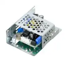
Illustrative purposes only

LHA10F-5-SNY
AC/DC Enclosed Power Supply (PSU), ITE, 1 Outputs, 10 W, 5 V, 2 A
⚠️ Reference pricing provided. In case of supply shortages, we will connect you with our trusted procurement partners to ensure your project's continuity.
- Manufacturer: COSEL
- Product type: AC / DC Enclosed Power Supplies
- SVHC: Lead (04-Feb-2026)
- Product Range: LHA Series
- No. of Outputs: 1Outputs
- Output Power Max: 10W
- Current, Output 4: -
- Input Voltage VAC: 85V AC to 264V AC
- Power Supply Output Type: Fixed
- Output Current - Output 1: 2A
- Output Current - Output 2: -
- Output Current - Output 3: -
- Output Voltage - Output 1: 5V
- Output Voltage - Output 2: -
- Output Voltage - Output 3: -
- Output Voltage - Output 4: -
- Power Supply Applications: ITE
| Delivery and price | |
|---|---|
| Units per pack | 100 |
| Price | 20.93 € |
| Current stock | 25+ |
| Lead time | 30 days |
Datasheet

**AC-DC Power Supplies Open Frame** ~~Po~~ 12 1 LeeS Power World wide Safety EMI Inrush OCP OVP Cost Rugged Factor Approvals current Effective PCB type Correction limiting

## **LHA-series**

## ~~ao~~ **Feature CE marking**

EN62477-1 (OVC III)

Low Voltage Directive RoHS Directive

Low-profile Small and compact PCB construction High efficiency Low noise Harmonic attenuator (Complies with IEC61000-3-2) Power factor correction (LHA75F-300F) Universal input (85-264VAC)

## **UKCA marking**

## a

Electrical Equipment Safety Regulations RoHS Regulations

## ~~o~~ **EMI**

Built-in inrush current, overcurrent and overvoltage protection circuits

Complies with FCC-B, CISPR11-B, CISPR32-B, EN55011-B, EN55032-B, VCCI-B

## **Safety agency approvals**

## ~~a~~ **Safety agency approvals** ~~o~~

## **EMS Compliance** : EN61204-3, EN61000-6-2

UL62368-1, C-UL (equivalent to CAN/CSA-C22.2 No.62368-1), EN62368-1

EN61000-4-2 EN61000-4-3 EN61000-4-4 EN61000-4-5 EN61000-4-6 EN61000-4-8 EN61000-4-11

EN62477-1 (OVC III) : LHA150F, 300F Complies with DEN-AN

~~a~~ **5-year warranty (refer to Instruction Manual)**

**LHA-1**

www.cosel.co.jp/en/

December 27, 2022

**Ordering information**

**AC-DC Power Supplies Open Frame**

**==> picture [58 x 26] intentionally omitted <==**

**----- Start of picture text -----**<br>
R<br>= \ (D)<br>**----- End of picture text -----**<br>


## **LHA10F**

**==> picture [227 x 25] intentionally omitted <==**

**----- Start of picture text -----**<br>
-<br> LH  A  10  F  OO  - O<br>1  2  3  4  5  6<br>**----- End of picture text -----**<br>


**==> picture [46 x 7] intentionally omitted <==**

**----- Start of picture text -----**<br>
1Series name<br>**----- End of picture text -----**<br>


**==> picture [175 x 102] intentionally omitted <==**

**----- Start of picture text -----**<br>
Example recommended EMI/EMC filter<br>EAC-03-472 2Single output<br>3Output wattage<br>| | 4Universal input<br>Fy 56Output voltageOptional  [*][1]<br>é t C : with Coating<br>é J4 : EP (TE Connectivity) connector type<br> S : with Chassis<br>High voltage pulse noise type : EAP series SN : with Chassis & cover<br>Low leakage current type : EAM series<br> Y : with Potentiometer<br>*A higher current rating EMI/EMC filter<br>may be recommended in view of the<br>other devices that could be connected<br>in parallel with the power supply.<br>**----- End of picture text -----**<br>


For option details, refer to Instruction Manual 6.

This power supply is manufactured by SMD technology. The stress to PCB like twisting or bending causes the defect of the unit, so handle the unit with care.

*Make sure necessary tests will be carried out on your end equipment with the power supply installed in accordance with any required EMC/EMI regulations.

||**MODEL**<br>~~a~~|**MODEL**<br>~~a~~|**LHA10F-3R3-Y**|**LHA10F-5**|**LHA10F-12**|**LHA10F-15**|**LHA10F-24**|
|---|---|---|---|---|---|---|---|
|**INPUT**|**VOLTAGE[VAC]**<br>*2 <br>~~Po~~||85 - 264 1f(Refer to “Derating” and Instruction Manual 1.1)|||||
||**CURRENT[A]**<br>~~i~~|**ACIN 100V**<br>~~i~~|0.18typ<br>~~i~~|0.26typ||||
|||**ACIN 230V**<br>~~i~~<br>~~a~~|0.10typ<br>~~i~~|0.14typ||||
||**FREQUENCY[Hz]**<br>~~Po~~<br>~~B+~~||50 / 60(45 - 440)<br>~~B+—_]~~|||||
||**EFFICIENCY[%]**<br>~~B+~~|**ACIN 100V**<br>~~B+~~<br>~~a~~|72.0typ<br>~~B+~~<br>~~es~~|77.0typ<br>~~B+~~|79.5typ<br>~~B+~~|81.0typ<br>~~—_]~~|82.5typ<br>~~—_]~~|
|||**ACIN 230V**<br>~~B+~~<br>~~a~~|72.0typ<br>~~B+~~<br>~~es~~|78.5typ<br>~~B+~~|81.0typ<br>~~B+~~|83.0typ<br>~~—_]~~|84.5typ<br>~~—_]~~|
||**INRUSH CURRENT[A]**<br>~~B+~~<br>~~po~~|**ACIN 100V**<br>~~B+~~<br>~~a~~<br>~~po~~|15typ (Io=100%)<br>~~B+ —_]~~<br>~~es~~|||||
|||**ACIN 230V**<br>~~po~~|35typ (Io=100%)|||||
||**LEAKAGE CURRENT[mA]**<br>~~po~~<br>~~Po~~||0.07 / 0.15max(ACIN 100V / 240V,60Hz,Io=100%,Accordingto IEC62368-1,and DEN-AN)|||||
|**OUTPUT**<br>~~Po~~|**VOLTAGE[V]**<br>~~ae~~||3.3<br>~~ae~~|5<br>~~ae~~|12<br>~~ae~~|15<br>~~ae~~|24|
||**CURRENT[A]**<br>*2 <br>~~a~~||2.0<br>~~PC~~|2.0<br>~~PC~~|0.9<br>~~PC~~|0.7<br>~~PC~~|0.5|
||**LINE REGULATION[mV]**<br>*3 <br>~~Ge~~||20max<br>~~Ge~~|20max<br>~~Ge~~|48max<br>~~Ge~~|60max<br>~~Ge~~|96max|
||**LOAD REGULATION[mV]**<br>*3 <br>~~Ge~~||40max<br>~~Ge~~|40max<br>~~Ge~~|100max<br>~~Ge~~|120max<br>~~Ge~~|150max|
||**RIPPLE[mVp-p]**<br>*4|**0 to +60**C *7 <br>~~**a**~~|80max<br>|80max<br>|120max<br>~~fo~~<br>|120max<br>~~fo~~<br>|120max<br>|
|||**-10 to 0**C<br>~~**a** ~~|140max<br> ~~a~~|140max<br>|160max<br>~~fo~~<br>|160max<br>~~fo~~<br>|160max<br>|
|||**Io=0 to 25%**<br>~~**a** ~~|300max<br> ~~a~~|300max<br>~~a~~|300max<br>~~fo~~<br>~~a~~|300max<br>~~fo~~<br>~~a~~|300max<br>~~a~~|
||**RIPPLE NOISE[mVp-p]**<br>*4<br>~~Po~~|**0 to +60**C *7 <br>~~a~~|120max<br>~~a~~<br>~~a~~|120max<br>~~a~~<br>~~a~~|150max<br>~~a~~<br>~~a~~|150max<br>~~a~~<br>~~a~~|150max|
|||**-10 to 0**C|160max|160max|180max|180max|180max|
|||**Io=0 to 25%**<br>~~a~~<br>|360max<br>~~a~~|360max|360max|360max<br>~~———~~|360max|
||**TEMPERATURE REGULATION[mV]**<br>~~Po~~|**0 to +60**C<br>*7 <br>~~a~~|50max<br>~~a~~|50max|120max|150max<br>~~———~~|240max|
|||**-10 to +60**C<br>*7 <br><br>~~a~~|60max<br>~~a~~|60max|150max|180max<br>~~———~~|290max|
||**DRIFT[mV]**<br>*5 <br><br>~~Po~~<br>~~Ge~~||20max<br>~~a~~<br>~~Ge~~|20max<br>~~Ge~~|48max<br>~~Ge~~|60max<br>~~———~~<br>~~Ge~~|96max|
||**START-UP TIME[ms]**<br>~~Po~~||40typ (ACIN 100V,Io=100%)|||||
||**HOLD-UP TIME[ms]**<br>~~Po~~||20typ (ACIN 100V,Io=100%)/ 150typ (ACIN 230V,Io=100%)|||||
||**OUTPUT VOLTAGE ADJUSTMENT RANGE[V]**<br>~~ee~~||2.85 to 3.63<br>~~ee~~|Fixed(“Y”option is available for adjustingoutput voltage between±10%)||||
||**OUTPUT VOLTAGE SETTING[V]**<br>~~a~~||3.30 to 3.40|4.90 to 5.30|11.50 to 12.50|14.40 to 15.60|23.00 to 25.00|
|**PROTECTION**<br>**CIRCUIT AND**<br>**OTHERS**|**OVERCURRENT PROTECTION**<br>~~Po~~||Works over 105% of ratingand recovers automatically|||||
||**OVERVOLTAGE PROTECTION**<br>~~Ge~~||4.00 to 6.00<br>~~Ge~~|5.75 to 8.00<br>~~Ge~~|13.80 to 18.00<br>~~Ge~~|17.25 to 23.30<br>~~Ge~~|27.60 to 34.50|
||**OPERATING INDICATION**<br>~~Po~~||Notprovided|||||
||**REMOTE SENSING**<br>~~Po~~||Notprovided|||||
|**ISOLATION**|**INPUT-OUTPUT**<br>~~Po~~||AC3,000V 1minute,Cutoff current = 10mA,DC500V 100MWmin(At Room Temperature)|||||
||**INPUT-FG**<br>~~Po~~||AC2,000V 1minute,Cutoff current = 10mA,DC500V 100MWmin(At Room Temperature)|||||
||**OUTPUT-FG**<br>~~Po~~||AC500V 1minute,Cutoff current = 25mA,DC500V 100MWmin(At Room Temperature)|||||
|**ENVIRONMENT**|**OPERATING TEMP.,HUMID.AND ALTITUDE** *2 <br>~~Po~~||-10 to +70C,20 - 90%RH(Non condensing),5,000m (16,500feet)max|||||
||**STORAGE TEMP.,HUMID.AND ALTITUDE**<br>~~Po~~||-20 to +75C,20 - 90%RH(Non condensing),9,000m(30,000feet)max|||||
||**VIBRATION**<br>~~Po~~||10 - 55Hz,19.6m/s2 (2G),3minutesperiod,60minutes each alongX,Y and Z axis|||||
||**IMPACT**<br>~~Po~~||196.1m/s2 (20G),11ms,once each X,Y and Z axis|||||
|**SAFETY AND**<br>**NOISE**<br>**REGULATIONS**|**AGENCY APPROVALS**<br>~~Po~~||UL62368-1,C-UL(equivalent to CAN/CSA-C22.2No.62368-1),EN62368-1,Complies with DEN-AN|||||
||**CONDUCTED NOISE**<br>~~Po~~||Complies with FCC-B,VCCI-B,CISPR11-B,CISPR32-B,EN55011-B,EN55032-B|||||
||**HARMONIC ATTENUATOR** *6 <br>~~Po~~||Complies with IEC61000-3-2(Class A) (No built-inpower factor correction)|||||
|**OTHERS**|**CASE SIZE/WEIGHT**<br>~~Po~~||50X21.5X62.5mm[1.97X0.85X2.46 inches] (WXHXD)/ 45gmax|||||
||**COOLING METHOD**<br>*2 <br>~~Po~~||Convection/Forced air(Requires external fan) (Refer to “Derating”)|||||


- *1 The listed options may affect the published standard specifications. Please contact us for detailed product specifications.

- *2 Derating is required.

- *3 At low load conditions, the burst mode operation will start.  To check load regulation, you will need to measure the characteristics at average mode with instruments.

- *4 This is the value that measured on measuring board with capacitor of 22mF and 0.1mF at 150mm from output terminal. Measured by 20MHz oscilloscope or Ripple-Noise meter (Equivalent to KEISOKU-GIKEN:RM104).

- *5

- *6

- *7

-

-

-

   - Drift is the change in DC output for an eight hour period after a half-hour warm-up at 25C, with the input voltage held constant at the rated input/output.

   - Please contact us about another class. When two or more units are operating it may not comply with the IEC61000-3-2. Please contact us for details.

   - 3.3V, 5V, 12V output product, the maximum temperature of 55C.

   - To meet the specification, do not operate overload condition. Parallel operation is not possible.

   - Sound noise may be generated by power supply in case of pulse load.

- Ripple and ripple noise spec is change at Io=0 to 25% by burst operation.

- Audible noise may be generated.

**LHA-2**

www.cosel.co.jp/en/

December 27, 2022

**LHA10F**

## **Block diagram**

**==> picture [461 x 224] intentionally omitted <==**

**----- Start of picture text -----**<br>
FUSE<br>AC250V<br>1.25A INRUSH RECTIFIER<br>AC IN NOISE<br>CURRENT AND<br>85 - 264VAC FILTER<br>LIMIT FILTER<br>FG<br>TRANSFORMER<br>RECTIFIER<br>INVERTER AND DC OUT<br>FILTER<br>CURRENT<br>CONTROL<br>SENSING<br>OVER VOLTAGE<br>PROTECTION<br>Photocoupler<br>CONTROL<br>**----- End of picture text -----**<br>


## **External view**

¶ External size of option is different from standard type.

**==> picture [477 x 263] intentionally omitted <==**

**----- Start of picture text -----**<br>
Standard type Chassis and cover type<br>5 72.5 ± 0.5<br>[0.2] [2.85]<br>Name plate Point  1 Point  2<br>FG Point  1 Point  2<br>Voltage adjust CN2<br>(LHA10F-3R3-Y or Optional -Y)<br>5 FG FG 5<br>3 AC(N) CN2 12 +V-V AC(N) 3 12 -V<br>1 AC(L) 1 +V<br>CN1 AC(L) CN1<br>Name plate 5 2- f 3.5[ f 0.14] 2- f 3.5[ f 0.14] Voltage adjust 15 4-M3<br>[0.2] Mounting Hole Mounting Hole (LHA10F-3R3-SNY [0.59] Mounting Hole<br>or Optional -SNY)<br>4 54.5 ± 0.5 82.5<br>[0.16] [2.15]<br>[3.25]<br>62.5 5 72.5 ± 0.5 2-M3<br>[2.46] [0.2] [2.85] Mounting Hole<br>PCB t=1.6[0.06]<br>f 3.5[ f 0.14]<br>Mounting Hole<br>10 [0.39]<br>20<br>[0.79] 30<br>3.5 [1.18]<br>[0.14]<br>0.5 0.5 0.5<br>50 ± 60 ± ±<br>[1.97] 42 [1.65] [2.36] 20 [0.79] 40 [1.57]<br>14.1 [0.56] 19.1 [0.75]<br>4<br>[0.16]<br>18 [0.71] 32 [1.26] 31 [1.22] 27 [1.06] 3.5 [0.14]<br>16<br>[0.63]<br>3.5max<br>[0.14max]<br>**----- End of picture text -----**<br>


|¶ The back side of PCB of the power supply is assembled some||CN1|CN2||
|---|---|---|---|---|
|SMDs.||Pin No.<br>Input|Pin No.|Output|
|Be careful not to bump against the attached area by vibration.<br>¶ Use the spacer of 8mm [0.31] length or more for isolation.||1<br>AC(L)<br>2|1|-V|
|And do not use press-fitting bush.<br>¶ Point1, Point2are thermometry points. Please refer to<br>Instruction Manual 3.||3<br>AC(N)<br>4<br>5<br>FG|2|+V|
|I/O Connector<br>Matingconnector<br>CN1 B3P5-VH<br>VHR-5N<br>Chain<br>Loose<br>Terminal<br>SVH-21T-P1.1<br>BVH-21T-P1.1||¶Pin No.2 and 4 is NC at CN1.|||
|CN2 B2P-VH<br>VHR-2N<br>Chain<br>Loose<br>SVH-21T-P1.1<br>BVH-21T-P1.1||¶Dimensions in mm, [  ]=inches<br>¶Tolerance :±1 [±0.04]|||
|(Mfr: J.S.T.)||¶Weight : 45g max (with chassis<br>||and cover :<br>|


- The back side of PCB of the power supply is assembled some SMDs.

- Use the spacer of 8mm [0.31] length or more for isolation. And do not use press-fitting bush.

- Point 1 , Point 2 are thermometry points. Please refer to Instruction Manual 3.

   - Weight : 45g max (with chassis and cover : 115g max)

   - PCB Material / thickness : CEM-3 / 1.6mm [0.06]

- I/O Connector is Mfr.J.S.T.

   - Optional chassis and cover material : Galvanizing steel board

- Option:-J4:EP (TE Connectivity) connector type.

- Mounting torque (Mounting hole of chassis) : 1.5N ・ m max

**LHA-3**

www.cosel.co.jp/en/

December 27, 2022

**AC-DC Power Supplies Open Frame**

## **Ordering information**

## **LHA15F**

**==> picture [108 x 26] intentionally omitted <==**

**----- Start of picture text -----**<br>
° R UK<br>Wis DC E LK<br>**----- End of picture text -----**<br>


**LH A 15 F** OO **-** O 1 2 3 4 5 6

**==> picture [175 x 123] intentionally omitted <==**

**----- Start of picture text -----**<br>
1Series name<br>Example recommended EMI/EMC filter<br>EAC-03-472 2Single output<br>3Output wattage<br>| .. 4Universal input<br>if4 56Output voltageOptional  [*][1]<br>~ q CJ4 :: with CoatingEP (TE Connectivity) connector type<br>High voltage pulse noise type : EAP series =  S : with ChassisSN : with Chassis & cover<br>Low leakage current type : EAM series<br> Y : with Potentiometer<br>*A higher current rating EMI/EMC filter<br>may be recommended in view of the<br>other devices that could be connected<br>in parallel with the power supply.<br>For option details, refer to<br>Instruction Manual 6.<br>**----- End of picture text -----**<br>


This power supply is manufactured by SMD technology. The stress to PCB like twisting or bending causes the defect of the unit, so handle the unit with care.

*Make sure necessary tests will be carried out on your end equipment with the power supply installed in accordance with any required EMC/EMI regulations.

||**MODEL**<br>~~a~~|**MODEL**<br>~~a~~|**LHA15F-3R3-Y**|**LHA15F-5**|**LHA15F-12**|**LHA15F-15**|**LHA15F-24**|
|---|---|---|---|---|---|---|---|
|**INPUT**|**VOLTAGE[VAC]**<br>*2 <br>~~Jo~~||85 - 264 1f(Refer to “Derating” and Instruction Manual 1.1)|||||
||**CURRENT[A]**<br>~~2~~|**ACIN 100V**<br>~~eee~~|0.24typ<br>~~eee~~|0.35typ||||
|||**ACIN 230V**<br>~~eee~~<br>~~po~~|0.15typ<br>~~eee~~<br>~~po~~|0.19typ||||
||**FREQUENCY[Hz]**<br>~~Po~~<br>~~ce ee~~||50 / 60(45 - 440)<br>~~ee~~<br>~~eeeeeee~~|||||
||**EFFICIENCY[%]**<br>~~ce~~|**ACIN 100V**<br>~~ce ee~~|71.5typ<br>~~ee~~|75.0typ<br>~~ee~~|79.0typ<br>~~ee~~|80.0typ<br>~~eee~~|81.5typ|
|||**ACIN 230V**<br>~~ce ee~~<br>~~a~~|72.5typ<br>~~ee~~<br>~~eG~~|77.0typ<br>~~ee~~<br>~~eG~~|82.0typ<br>~~ee~~<br>~~eG~~|83.0typ<br>~~eee~~<br>~~eG~~|84.5typ|
||**INRUSH CURRENT[A]**<br>~~ce~~<br>~~|~~|**ACIN 100V**<br>~~ce ee~~<br>~~|~~|15typ (Io=100%)Ta=25Cat cold start<br>~~ee~~<br>~~ee ee eee~~|||||
|||**ACIN 230V**<br>~~||~~|35typ (Io=100%)Ta=25Cat cold start|||||
||**LEAKAGE CURRENT[mA]**<br>~~||~~<br>~~Po~~||0.05 / 0.10max(ACIN 100V / 240V,60Hz,Io=100%,Accordingto IEC62368-1,and DEN-AN)|||||
|**OUTPUT**<br>~~||~~|**VOLTAGE[V]**<br>~~a ~~||3.3<br> ~~DC~~|5<br>~~DC~~|12<br>~~DC~~|15<br>~~DC~~|24|
||**CURRENT[A]**<br>*2 <br>~~a~~||3.0<br>~~GG~~|3.0<br>~~GG~~|1.3<br>~~GG~~|1.0<br>~~GG~~|0.7|
||**LINE REGULATION[mV]**<br>*3 <br>~~a~~||20max<br>~~eG~~|20max<br>~~eG~~|48max<br>~~eG~~|60max<br>~~eG~~|96max|
||**LOAD REGULATION[mV]**<br>*3 <br>~~a ~~||40max<br> ~~GG~~|40max<br>~~GG~~|100max<br>~~GG~~|120max<br>~~GG~~|150max|
||**RIPPLE[mVp-p]**<br>*4|**0 to +60**C<br>*7 <br>~~Po~~|80max<br>~~Po~~|80max<br>~~Po~~|120max<br>~~Po~~|120max<br>~~Po~~|120max|
|||**-10 to 0**C<br>~~Po~~|140max<br>~~Po~~|140max<br>~~Po~~|160max<br>~~Po~~|160max<br>~~Po~~|160max|
|||**Io=0 to 25%**<br>~~PO~~|300max<br>~~PO~~|300max<br>~~PO~~|300max<br>~~PO~~|300max<br>~~PO~~|300max|
||**RIPPLE NOISE[mVp-p]**<br>*4<br>~~Po~~|**0 to +60**C<br>*7 <br>~~PO~~<br>~~Po~~|120max<br>~~PO~~<br>|120max<br>~~PO~~<br>|150max<br>~~PO~~<br>|150max<br>~~PO~~<br>|150max|
|||**-10 to 0**C<br>~~Po~~|160max<br>|160max<br>|180max<br>|180max<br>|180max|
|||**Io=0 to 25%**<br>~~PoPo~~|360max<br>~~Po~~|360max<br>~~Po~~|360max<br>~~Po~~|360max<br>~~Po~~|360max|
||**TEMPERATURE REGULATION[mV]**<br>~~ca~~<br>~~RR~~|**0 to +60**C *7 <br>~~ca~~<br>~~RR~~|50max<br>~~ee~~<br>~~GC~~|50max<br>~~ee~~<br>~~GC~~|120max<br>~~ee~~<br>~~GC~~|150max<br>~~ee~~<br>~~GC~~|240max|
|||**-10 to +60**C<br>*7 <br>~~ca~~<br>~~RR~~|60max<br>~~ee~~<br>~~GC~~|60max<br>~~ee~~<br>~~GC~~|150max<br>~~ee~~<br>~~GC~~|180max<br>~~ee~~<br>~~GC~~|290max|
||**DRIFT[mV]**<br>*5 <br>~~RR~~<br>~~RG~~<br>~~|~~||20max<br>~~GC~~<br>~~RG~~<br>|20max<br>~~GC~~<br>~~RG~~|48max<br>~~GC~~<br>~~RG~~|60max<br>~~GC~~<br>~~RG~~|96max|
||**START-UP TIME[ms]**<br>~~||~~||40typ (ACIN 100V,Io=100%)<br>|||||
||**HOLD-UP TIME[ms]**<br>~~||~~||20typ (ACIN 100V,Io=100%)/ 150typ (ACIN 230V,Io=100%)<br>|||||
||**OUTPUT VOLTAGE ADJUSTMENT RANGE[V]**<br>~~|Po~~||2.85 to 3.63<br>~~Po~~|Fixed(“Y”option is available for adjustingoutput voltage between±10%)||||
||**OUTPUT VOLTAGE SETTING[V]**<br>~~GC~~||3.30 to 3.40<br>~~GC~~|4.90 to 5.30<br>~~GC~~|11.50 to 12.50<br>~~GC~~|14.40 to 15.60<br>~~GC~~|23.00 to 25.00|
|**PROTECTION**<br>**CIRCUIT AND**<br>**OTHERS**|**OVERCURRENT PROTECTION**<br>~~Jo~~||Works over 105% of ratingand recovers automatically|||||
||**OVERVOLTAGE PROTECTION**<br>~~RG~~||4.00 to 6.00<br>~~RG~~|5.75 to 8.00<br>~~RG~~|13.80 to 18.00<br>~~RG~~|17.25 to 23.30<br>~~RG~~|27.60 to 34.50|
||**OPERATING INDICATION**<br>~~ee~~||Notprovided|||||
||**REMOTE SENSING**<br>~~Po~~||Notprovided|||||
|**ISOLATION**|**INPUT-OUTPUT**<br>~~J~~||AC3,000V 1minute,Cutoff current = 10mA,DC500V 100MWmin(At Room Temperature)|||||
||**INPUT-FG**<br>~~Po~~||AC2,000V 1minute,Cutoff current = 10mA,DC500V 100MWmin(At Room Temperature)|||||
||**OUTPUT-FG**<br>~~Po~~||AC500V 1minute,Cutoff current = 25mA,DC500V 100MWmin(At Room Temperature)|||||
|**ENVIRONMENT**|**OPERATING TEMP.,HUMID.AND ALTITUDE** *2 <br>~~Jo~~||-10 to +70C,20 - 90%RH(Non condensing),5,000m(16,500feet)max|||||
||**STORAGE TEMP.,HUMID.AND ALTITUDE**<br>~~Po~~||-20 to +75C,20 - 90%RH(Non condensing),9,000m(30,000feet)max|||||
||**VIBRATION**<br>~~Po~~||10 - 55Hz,19.6m/s2 (2G),3minutesperiod,60minutes each alongX,Y and Z axis|||||
||**IMPACT**<br>~~Po~~||196.1m/s2 (20G),11ms,once each X,Y and Z axis|||||
|**SAFETY AND**<br>**NOISE**<br>**REGULATIONS**|**AGENCY APPROVALS**<br>~~J~~||UL62368-1,C-UL(equivalent to CAN/CSA-C22.2No.62368-1),EN62368-1,Complies with DEN-AN|||||
||**CONDUCTED NOISE**<br>~~Po~~||Complies with FCC-B,VCCI-B,CISPR11-B,CISPR32-B,EN55011-B,EN55032-B|||||
||**HARMONIC ATTENUATOR** *6 <br>~~Po~~||Complies with IEC61000-3-2(Class A) (No built-inpower factor correction)|||||
|**OTHERS**|**CASE SIZE/WEIGHT**<br>~~J~~||50X21.5X73.5mm[1.97X0.85X2.89 inches] (WXHXD)/ 60gmax|||||
||**COOLING METHOD**<br>*2 <br>~~Po~~||Convection/Forced air(Requires external fan) (Refer to “Derating”)|||||


- *1 The listed options may affect the published standard specifications. Please contact us for detailed product specifications.

- *2 Derating is required.

- *3 At low load conditions, the burst mode operation will start.  To check load regulation, you will need to measure the characteristics at average mode with instruments.

- *4 This is the value that measured on measuring board with capacitor of 22mF and 0.1mF at 150mm from output terminal. Measured by 20MHz oscilloscope or Ripple-Noise meter (Equivalent to KEISOKU-GIKEN:RM104).

- *5

- *6

- *7

-

-

-

   - Drift is the change in DC output for an eight hour period after a half-hour warm-up at 25C, with the input voltage held constant at the rated input/output.

   - Please contact us about another class. When two or more units are operating it may not comply with the IEC61000-3-2. Please contact us for details.

   - 3.3V, 5V, 12V output product, the maximum temperature of 55C.

   - To meet the specification, do not operate overload condition. Parallel operation is not possible.

   - Sound noise may be generated by power supply in case of pulse load.

- Ripple and ripple noise spec is change at Io=0 to 25% by burst operation.

- Audible noise may be generated.

**LHA-4**

www.cosel.co.jp/en/

December 27, 2022

**LHA15F**

## **Block diagram**

**==> picture [461 x 224] intentionally omitted <==**

**----- Start of picture text -----**<br>
FUSE<br>AC250V<br>1.25A INRUSH RECTIFIER<br>AC IN NOISE<br>CURRENT AND<br>85 - 264VAC FILTER<br>LIMIT FILTER<br>FG<br>TRANSFORMER<br>RECTIFIER<br>INVERTER AND DC OUT<br>FILTER<br>CURRENT<br>CONTROL<br>SENSING<br>OVER VOLTAGE<br>PROTECTION<br>Photocoupler<br>CONTROL<br>**----- End of picture text -----**<br>


## **External view**

**==> picture [485 x 380] intentionally omitted <==**

**----- Start of picture text -----**<br>
¶  External size of option is different from standard type.<br>Standard type Chassis and cover type<br>5 83.5 ± 0.5<br>Point  ① [0.2] [3.29] Voltage adjust<br>(LHA15F-3R3-SNY<br>Voltage adjust Name plate Point  ① or Optional -SNY)<br>FG (LHA15F-3R3-Y or Optional -Y)<br>Point  ②<br>Point  ②<br>5 FG FG 5<br>3 AC(N) AC(N) 3<br>1 AC(L) 12 +V-V AC(L) 1 12 +V-V<br>CN1 CN2 CN1 CN2<br>Name plate 13.7 2- f 3.5[ f 0.14] 2- f 3.5[ f 0.14] 23.7 4-M3<br>[0.54] Mounting Hole Mounting Hole [0.93] Mounting Hole<br>5 63.5 ± 0.5 93.5<br>[0.2] [2.5] [3.68]<br>73.5 5 83.5 ± 0.5 2-M3<br>[2.89] [0.2] [3.29] Mounting Hole<br>PCB t=1.6[0.06]<br>f 3.5[ f 0.14]<br>Mounting Hole<br>¶ The back side of PCB of the power supply is assembled some  CN1 CN2<br>SMDs. Pin No. Input Pin No. Output<br>Be careful not to bump against the attached area by vibration. 1 AC(L)<br>¶ Use the spacer of 8mm [0.31] length or more for isolation. 2 1 -V<br>And do not use press-fitting bush. 3 AC(N)<br>¶ Point  1 , Point  2  are thermometry points. Please refer to  4 2 +V<br>Instruction Manual 3.<br>5 FG<br>I/O Connector Mating connector Terminal<br>¶  Pin No.2 and 4 is NC at CN1.<br>Chain SVH-21T-P1.1<br>CN1 B3P5-VH VHR-5N<br>Loose BVH-21T-P1.1<br>CN2 B2P-VH VHR-2N ChainLoose SVH-21T-P1.1BVH-21T-P1.1 ¶¶  Dimensions in mm, [  ]=inches Tolerance :  ± 1 [ ± 0.04]<br>10<br>[0.39]<br>20<br>[0.79]<br>3.5 30<br>[0.14] [1.18]<br>50 [1.97] 400.5 ± [1.57] 60 [2.36] 200.5 ± [0.79] 400.5 ± [1.57]<br>25.6 [1.01] 30.6 [1.2]<br>5<br>[0.2]<br>18 [0.71] 32 [1.26] 31 [1.22] 27 [1.06] 3.5 [0.14]<br>16<br>[0.63]<br>3.5max<br>[0.14max]<br>**----- End of picture text -----**<br>


- The back side of PCB of the power supply is assembled some SMDs. Be careful not to bump against the attached area by vibration.

- Use the spacer of 8mm [0.31] length or more for isolation. And do not use press-fitting bush.

- Point 1 , Point 2 are thermometry points. Please refer to Instruction Manual 3.

   - Tolerance : ± 1 [ ± 0.04]

   - Weight : 60g max (with chassis and cover : 140g max)

- (Mfr: J.S.T.)

   - PCB Material / thickness : CEM-3 / 1.6mm [0.06]

- I/O Connector is Mfr.J.S.T.

   - Optional chassis and cover material : Galvanizing steel board

- Option:-J4:EP (TE Connectivity) connector type.

- Mounting torque (Mounting hole of chassis) : 1.5N ・ m max

**LHA-5**

www.cosel.co.jp/en/

December 27, 2022

**AC-DC Power Supplies Open Frame LHA30F** ~~|~~

**Ordering information**

**LH A 30 F** OO **-** O

1 2 3 4 5 6

**==> picture [2 x 3] intentionally omitted <==**

**----- Start of picture text -----**<br>
R<br>**----- End of picture text -----**<br>


1Series name **Example recommended EMI/EMC filter EAC-03-472** 2Single output 3Output wattage 4Universal input 5Output voltage Sad 6Optional[*][1] C : with Coating me ' G: Low leakage current J4 : EP (TE Connectivity) connector type High voltage pulse noise type : EAP series : S : with Chassis Low leakage current type : EAM series SN : with Chassis & cover *A higher current rating EMI/EMC filter Y : with Potentiometer may be recommended in view of the other devices that could be connected in parallel with the power supply.

For option details, refer to Instruction Manual 6.

This power supply is manufactured by SMD technology. The stress to PCB like twisting or bending causes the defect of the unit, so handle the unit with care.

*Make sure necessary tests will be carried out on your end equipment with the power supply installed in accordance with any required EMC/EMI regulations.

||**MODEL**<br>~~PT~~|**MODEL**<br>~~PT~~|**LHA30F-3R3-Y**<br>~~PT~~|**LHA30F-5**<br>~~PT~~|**LHA30F-12**<br>~~PT~~|**LHA30F-15**<br>~~PT~~|**LHA30F-24**|
|---|---|---|---|---|---|---|---|
|**INPUT**|**VOLTAGE[VAC]**<br>*2 <br>~~Po~~<br>~~———es~~||85 - 264 1f (Refer to “Derating” and Instruction Manual 1.1)<br>~~es~~|||||
||**CURRENT[A]**<br>~~———~~|**ACIN 100V**<br>~~es~~|0.42typ<br>~~es~~|0.62typ||||
|||**ACIN 230V**<br>~~es~~|0.23typ<br>~~es~~|0.32typ||||
||**FREQUENCY[Hz]**<br>~~———es~~<br>~~Po~~<br>~~Bp~~||50 / 60(45 - 440)<br>~~es~~<br>~~Bp~~<br>~~f+—_]~~|||||
||**EFFICIENCY[%]**<br>~~Bp~~|**ACIN 100V**<br>~~Bp~~|83.0typ<br>~~Bp~~|83.0typ<br>~~Bp~~|85.0typ<br>~~f+—_]~~|85.5typ<br>~~f+—_]~~|87.0typ<br>~~f+—_]~~|
|||**ACIN 230V**<br>~~Bp~~<br>~~a~~|85.5typ<br>~~Bp~~|87.0typ<br>~~Bp~~|88.5typ<br>~~f+—_]~~|89.0typ<br>~~f+—_]~~|90.0typ<br>~~f+—_]~~|
||**INRUSH CURRENT[A]**<br>~~Bp~~<br>~~Ee~~<br>~~|~~|**ACIN 100V**<br>~~Bp~~<br>~~Ee~~<br>~~|~~|15typ (Io=100%)Ta=25Cat cold start<br>~~Bp~~<br>~~f+—_]~~|||||
|||**ACIN 230V**<br>~~Ee~~<br>~~|~~|35typ (Io=100%)Ta=25Cat cold start|||||
||**LEAKAGE CURRENT[mA]**<br>~~Ee~~<br>~~|~~<br>~~Po~~||0.20 / 0.45max(ACIN 100V / 240V  60Hz,Io=100%,Accordingto IEC62368-1 and DEN-AN)|||||
|**OUTPUT**<br>~~||~~<br>~~[|~~|**VOLTAGE[V]**<br>~~a~~||3.3<br>~~GG~~|5<br>~~GG~~|12<br>~~GG~~|15<br>~~GG~~|24|
||**CURRENT[A]**<br>*2 <br>~~a~~||6.0<br>~~GG~~|6.0<br>~~GG~~|2.5<br>~~GG~~|2.0<br>~~GG~~|1.3|
||**LINE REGULATION[mV]**<br>*3 <br>~~GG~~||20max<br>~~GG~~|20max<br>~~GG~~|48max<br>~~GG~~|60max<br>~~GG~~|96max|
||**LOAD REGULATION[mV]**<br>*3 <br>~~a~~||40max<br>~~GG~~|40max<br>~~GG~~|100max<br>~~GG~~|120max<br>~~GG~~|150max|
||**RIPPLE[mVp-p]**<br>*4<br>~~pp~~|**0 to +50**C <br>~~pp~~|80max<br>~~pp~~|80max<br>~~pp~~|120max<br>~~pp~~|120max<br>~~pp~~|120max|
|||**-10 to 0**C <br>~~pp~~<br>~~PO~~|140max<br>~~pp~~<br>~~PO~~|140max<br>~~pp~~<br>~~PO~~|160max<br>~~pp~~<br>~~PO~~|160max<br>~~pp~~<br>~~PO~~|160max|
|||**Io=0 to 15%** <br>~~pp~~<br>~~PO~~|300max<br>~~pp~~<br>~~PO~~|300max<br>~~pp~~<br>~~PO~~|300max<br>~~pp~~<br>~~PO~~|300max<br>~~pp~~<br>~~PO~~|300max|
||**RIPPLE NOISE[mVp-p]**<br>*4<br>~~a~~|**0 to +50**C <br>~~**Po**~~|120max<br>~~**Po**~~|120max<br>~~**Po**~~|150max<br>~~**Po**~~|150max<br>~~**Po**~~|150max|
|||**-10 to 0**C <br>~~**Po**~~|160max<br>~~**Po**~~|160max<br>~~**Po**~~|180max<br>~~**Po**~~|180max<br>~~**Po**~~|180max|
|||**Io=0 to 15%** <br>~~**Po**~~|360max<br>~~**Po**~~|360max<br>~~**Po**~~|360max<br>~~**Po**~~|360max<br>~~**Po**~~|360max|
||**TEMPERATURE REGULATION[mV]**<br>~~a~~<br>~~RR~~|**0 to +50**C <br>~~a~~<br>~~RR~~|50max<br>~~GC~~|50max<br>~~GC~~|120max<br>~~GC~~|150max<br>~~GC~~|240max|
|||**-10 to +50**C <br>~~a~~<br>~~RR~~|60max<br>~~GC~~|60max<br>~~GC~~|150max<br>~~GC~~|180max<br>~~GC~~|290max|
||**DRIFT[mV]**<br>*5 <br>~~RR~~<br>~~Ge~~<br>~~|~~||20max<br>~~GC~~<br>~~Ge~~<br>|20max<br>~~GC~~<br>~~Ge~~|48max<br>~~GC~~<br>~~Ge~~|60max<br>~~GC~~<br>~~Ge~~|96max|
||**START-UP TIME[ms]**<br>~~||~~||40typ (ACIN 100V,Io=100%)<br>|||||
||**HOLD-UP TIME[ms]**<br>~~||~~||25typ (ACIN 100V,Io=100%)/ 170typ (ACIN 230V,Io=100%)<br>|||||
||**OUTPUT VOLTAGE ADJUSTMENT RANGE[V]**<br>~~|ee~~||2.85 to 3.63<br>~~ee~~|Fixed(“Y”option is available for adjustingoutput voltage between±10%)||||
||**OUTPUT VOLTAGE SETTING[V]**<br>~~a~~<br>~~[|~~||3.30 to 3.40<br>~~Ga~~<br>|4.90 to 5.30<br>~~Ga~~<br>|11.50 to 12.50<br>|14.40 to 15.60<br>|23.00 to 25.00|
|**PROTECTION**<br>**CIRCUIT AND**<br>**OTHERS**<br>~~[|~~<br>~~PF~~|**OVERCURRENT PROTECTION**<br>~~[|~~||Works over 105% of ratingand recovers automatically<br>|||||
||**OVERVOLTAGE PROTECTION**<br>~~[|a ~~||4.00 to 5.25<br> ~~GG~~|5.75 to 7.00<br>~~GG~~|13.80 to 16.80<br>~~GG~~|17.25 to 21.00<br>~~GG~~|27.60 to 33.60|
||**OPERATING INDICATION**<br>~~ee~~||Notprovided|||||
||**REMOTE SENSING**<br>~~Po~~<br>~~PF~~||Notprovided|||||
|**ISOLATION**<br>~~PF~~|**INPUT-OUTPUT**<br>~~PF~~||AC3,000V 1minute,Cutoff current = 10mA,DC500V 100MWmin(At Room Temperature)|||||
||**INPUT-FG**<br>~~PFPo~~||AC2,000V 1minute,Cutoff current = 10mA,DC500V 100MWmin(At Room Temperature)|||||
||**OUTPUT-FG**<br>~~Po~~||AC500V 1minute,Cutoff current = 25mA,DC500V 100MWmin(At Room Temperature)|||||
|**ENVIRONMENT**|**OPERATING TEMP.,HUMID.AND ALTITUDE** *2 <br>~~Po~~||-10 to +70C,20 - 90%RH(Non condensing),5,000m(16,500feet)max|||||
||**STORAGE TEMP.,HUMID.AND ALTITUDE**<br>~~Po~~||-20 to +75C,20 - 90%RH(Non condensing),9,000m(30,000feet)max|||||
||**VIBRATION**<br>~~Po~~||10 - 55Hz,19.6m/s2 (2G),3minutesperiod,60minutes each alongX,Y and Z axis|||||
||**IMPACT**<br>~~Po~~||196.1m/s2 (20G),11ms,once each X,Y and Z axis|||||
|**SAFETY AND**<br>**NOISE**<br>**REGULATIONS**|**AGENCY APPROVALS**<br>~~Po~~||UL62368-1,C-UL(equivalent to CAN/CSA-C22.2No.62368-1),EN62368-1,Complies with DEN-AN|||||
||**CONDUCTED NOISE**<br>~~Po~~||Complies with FCC-B,VCCI-B,CISPR11-B,CISPR32-B,EN55011-B,EN55032-B|||||
||**HARMONIC ATTENUATOR** *6 <br>~~Po~~||Complies with IEC61000-3-2(Class A) (No built-inpower factor correction)|||||
|**OTHERS**|**CASE SIZE/WEIGHT**<br>~~Po~~||50X27X87.5mm[1.97X1.07X3.44 inches] (WXHXD)/ 100gmax(with chassis & cover : 210gmax)|||||
||**COOLING METHOD**<br>*2 <br>~~Po~~||Convection/Forced air(Requires external fan) (Refer to “Derating”)|||||


- *1 The listed options may affect the published standard specifications. Please contact us for detailed product specifications.

- *2 Derating is required.

- *3 At low load conditions, the burst mode operation will start.  To check load regulation, you will need to measure the characteristics at average mode with instruments.

- *4 This is the value that measured on measuring board with capacitor of 22mF and 0.1mF at 150mm from output terminal. Measured by 20MHz oscilloscope or Ripple-Noise meter (Equivalent to KEISOKU-GIKEN:RM104).

- *5 Drift is the change in DC output for an eight hour period after a half-hour warm-up at 25C, with the input voltage held constant at the rated input/output.

- *6

      - Please contact us about another class. When two or more units are operating it may not comply with the IEC61000-3-2. Please contact us for details.

      - To meet the specification, do not operate overload condition.

   -

   - Parallel operation is not possible.

   - Sound noise may be generated by power supply in case of pulse load.

- Ripple and ripple noise spec is change at Io=0 to 15% by burst operation.

**LHA-6**

www.cosel.co.jp/en/

December 27, 2022

**LHA30F**

## **Block diagram**

**==> picture [461 x 236] intentionally omitted <==**

**----- Start of picture text -----**<br>
FUSE<br>AC250V<br>2.5A INRUSH RECTIFIER<br>AC IN NOISE<br>CURRENT AND<br>85 - 264VAC FILTER<br>LIMIT FILTER<br>FG<br>TRANSFORMER<br>RECTIFIER<br>CONTROL INVERTER AND DC OUT<br>FILTER<br>CURRENT<br>SENSING<br>Photocoupler<br>CONTROL<br>Photocoupler<br>OVER VOLTAGE<br>PROTECTION<br>**----- End of picture text -----**<br>


## **External view**

¶ External size of option is different from standard type.

**==> picture [466 x 251] intentionally omitted <==**

**----- Start of picture text -----**<br>
Standard type Chassis and cover type<br>Voltage adjust<br>Voltage adjust [0.2]5 97.5[3.84]±0.5 (LHA30F-3R3-SNY or Optional -SNY)<br>Name plate (LHA30F-3R3-Y or Optional -Y) 14.8<br>FG 4.8 [0.58]<br>[0.19]<br>5 FG FG 5 -V<br>CN131 AC(N)AC(L) CN2 1234 -V+V AC(N)AC(L) CN131 1234 + V<br>Point 1 Point 2 2-f3.5 [f0.14] Point 1 Point 2 4-M4<br>5 77.5±0.5 Mounting Hole 2-Mounting Holef4.5 [f0.18] Name plate CN2 Mounting Hole<br>[0.2] [3.05]<br>87.5 107.5<br>[3.44] [4.23]<br>5 97.5±0.5 3-M4<br>[0.2] [3.84]<br>Mounting Hole<br>PCB t=1.6 [0.06]<br>2-f4.5 [f0.18]<br>Mounting Hole<br>22.9 [0.9] 10 [0.39]<br>20 [0.79]<br>17.9 [0.7] 4.5 [0.18] 30 [1.18]<br>50 [1.97] 40±0.5 [1.57] 60 [2.36] 20±0.5 [0.79] 40±0.5 [1.57]<br>5 [0.2]<br>4.5 [0.18]<br>0.5<br>23.5 [0.93] 37.5 [1.48] 35.5 [1.4] 19± [0.75]<br>18 [0.71]<br>3.5max [0.14max] 8.5 [0.33]<br>**----- End of picture text -----**<br>


- The back side of PCB of the power supply is assembled some SMDs.

Be careful not to bump against the attached area by vibration.

- Use the spacer of 8mm [0.31] length or more for isolation. And do not use press-fitting bush.

- Point 1 , Point 2 are thermometry points. Please refer to Instruction Manual 3.

|I/O Connector|I/O Connector|Matingconnector|Terminal|Terminal|
|---|---|---|---|---|
|CN1|B3P5-VH|VHR-5N|Chain|SVH-21T-P1.1|
||||Loose|BVH-21T-P1.1|
|CN2|B4P-VH|VHR-4N|Chain|SVH-21T-P1.1|
||||Loose|BVH-21T-P1.1|


   - (Mfr: J.S.T.)

- I/O Connector is Mfr.J.S.T.

- Option:-J4:EP (TE Connectivity) connector type.

CN1

## CN2

||Pin No.|Input||Pin No.|Output|
|---|---|---|---|---|---|
||1<br>2<br>3<br>4<br>5|AC(L)<br>AC(N)<br>FG||1, 2<br>3, 4|-V<br>+V|


- Pin No.2 and 4 is NC at CN1.

- Keep drawing current per pin below 5A for CN2.

- Dimensions in mm, [  ]=inches

- Tolerance : ± 1 [ ± 0.04]

- Weight : 100g max (with chassis and cover : 210g max)

- PCB Material / thickness : FR-4 / 1.6mm [0.06]

- Optional chassis and cover material : Galvanizing steel board

- Mounting torque (Mounting hole of chassis) : 1.5N ・ m max

**LHA-7**

www.cosel.co.jp/en/

December 27, 2022

**AC-DC Power Supplies Open Frame**

## **Ordering information**

## **LHA50F**

**==> picture [108 x 24] intentionally omitted <==**

**----- Start of picture text -----**<br>
> R UK<br>Ws D C E<br>**----- End of picture text -----**<br>


**LH A 50 F** OO **-** O 1 2 3 4 5 6

1Series name **Example recommended EMI/EMC filter EAC-03-472** 2Single output 3Output wattage | . 4Universal input 5Output voltage ey;th eS 6Optional[*][1] ae C : with Coating G: Low leakage current J4 : EP (TE Connectivity) connector type High voltage pulse noise type : EAP series S : with Chassis Low leakage current type : EAM series SN : with Chassis & cover *A higher current rating EMI/EMC filter Y : with Potentiometer may be recommended in view of the other devices that could be connected in parallel with the power supply.

For option details, refer to Instruction Manual 6.

This power supply is manufactured by SMD technology. The stress to PCB like twisting or bending causes the defect of the unit, so handle the unit with care.

*Make sure necessary tests will be carried out on your end equipment with the power supply installed in accordance with any required EMC/EMI regulations.

|~~-—~~|**MODEL**<br>~~SS~~<br>~~-—~~|**MODEL**<br>~~SS~~<br>~~-—~~|**LHA50F-3R3-Y **<br>|**LHA50F-5**<br>|**LHA50F-12**|**LHA50F-15**|**LHA50F-24**|**LHA50F-36**|**LHA50F-48**|
|---|---|---|---|---|---|---|---|---|---|
|**INPUT**<br>~~-—~~|**VOLTAGE[VAC]**<br>*2 <br>~~SS~~<br>~~-—~~||85 - 264 1f (Refer to “Derating” and Instruction Manual 1.1)<br>|||||||
||**CURRENT[A]**<br>~~-—EF~~|**ACIN 100V**<br>~~EF~~|0.56typ<br>~~EF~~|0.82typ<br>~~EF~~|1.05typ|||||
|||**ACIN 230V**<br>~~EF~~<br>~~a~~|0.30typ<br>~~EF~~|0.42typ<br>~~EF~~|0.52typ|||||
||**FREQUENCY[Hz]**<br>~~_—~~<br>~~a~~||50 / 60(45 - 440)<br>~~HNNJNM,~~<br>|||||||
||**EFFICIENCY[%]**<br>~~HA~~|**ACIN 100V**<br>~~HA~~<br>~~a~~|80.0typ<br>~~HA~~<br>|83.0typ<br>~~HA~~|87.0typ<br>~~HA~~|85.5typ<br>~~HA~~|86.0typ<br>~~HA~~<br>~~HNNJNM,~~|86.5typ<br>~~HA~~<br>~~JNM,~~|86.5typ<br>~~JNM,~~|
|||**ACIN 230V**<br>~~HA~~<br>~~a ~~|83.5typ<br>~~HA~~<br> ~~a~~|86.5typ<br>~~HA~~|90.5typ<br>~~HA~~|89.0typ<br>~~HA~~|89.0typ<br>~~HA~~<br>~~HNNJNM,~~|90.0typ<br>~~HA~~<br>~~JNM,~~|90.0typ<br>~~JNM,~~|
||**INRUSH CURRENT[A]**<br>~~po~~|**ACIN 100V**<br>~~a ~~<br>~~po~~|15typ (Io=100%)Ta=25Cat cold start<br>~~HNN JNM,~~<br>|||||||
|||**ACIN 230V**<br>~~po~~<br>~~—~~|35typ (Io=100%)Ta=25Cat cold start|||||||
||**LEAKAGE CURRENT[mA]**<br>~~po~~<br>~~—~~<br>~~SS~~||0.30 / 0.65max(ACIN 100V / 240V  60Hz,Io=100%,Accordingto IEC62368-1 and DEN-AN)|||||||
|**OUTPUT**<br>~~_—~~<br>~~_—~~|**VOLTAGE[V]**<br>~~SS~~<br>~~eS~~||3.3|5|12|15|24|36|48|
||**CURRENT[A]**<br>*2 <br>~~SS~~<br>~~eS~~<br>~~eS~~||8.0|8.0|4.3|3.5|2.1|1.4|1.1|
||**LINE REGULATION[mV]**<br>*3 <br>~~eS~~<br>~~eS~~<br>~~eS~~||20max|20max|48max|60max|96max|144max|192max|
||**LOAD REGULATION[mV]**<br>*3 <br>~~eS~~<br>~~eS~~<br>~~ee~~||40max<br>|40max|100max|120max|150max|240max|240max|
||**RIPPLE[mVp-p]**<br>*4<br>~~eS~~|**0 to +50**C <br>~~S~~<br>~~ee~~|80max<br>|80max|120max|120max|120max|150max|150max|
|||**-10 to 0**C <br>~~eea~~|140max<br>~~a~~|140max|160max|160max|160max|200max|200max|
|||**Io=0 to 15%** <br>~~a~~|300max<br>~~a~~|300max|300max|300max|300max|300max|300max|
||**RIPPLE NOISE[mVp-p]**<br>*4|**0 to +50**C <br>~~a~~|120max<br>~~a~~|120max|150max<br>~~a~~|150max<br>~~a~~|150max|250max|250max|
|||**-10 to 0**C <br>~~a~~|160max|160max|180max|180max|180max|300max|300max|
|||**Io=0 to 15%** <br>~~a~~<br>~~a~~|360max<br>~~a~~|360max|360max<br>~~ee~~|360max<br>~~ee~~|360max<br>~~ee~~|360max<br>~~ee~~|360max|
||**TEMPERATURE REGULATION[mV]**<br>~~———_——~~<br>~~eS~~|**0 to +50**C <br>~~———_——~~<br>~~a~~|50max<br>~~———_——~~<br>~~a~~|50max<br>~~———_——~~|120max<br>~~———_——~~<br>~~ee~~|150max<br>~~———_——~~<br>~~ee~~|240max<br>~~———_——~~<br>~~ee~~|360max<br>~~———_——~~<br>~~ee~~|480max|
|||**-10 to +50**C <br>~~———_——~~<br>~~a~~<br>~~eS~~|60max<br>~~———_——~~<br>~~a~~|60max<br>~~———_——~~|150max<br>~~———_——~~<br>~~ee~~|180max<br>~~———_——~~<br>~~ee~~|290max<br>~~———_——~~<br>~~ee~~|450max<br>~~———_——~~<br>~~ee~~|600max|
||**DRIFT[mV]**<br>*5 <br>~~a~~<br>~~eS~~<br>~~_—~~||20max<br>~~a~~|20max|48max<br>~~ee~~|60max<br>~~ee~~|96max<br>~~ee~~|144max<br>~~ee~~|192max|
||**START-UP TIME[ms]**<br>~~eS~~<br>~~_—~~<br>~~_—~~||40typ (ACIN 100V,Io=100%)<br>|||||||
||**HOLD-UP TIME[ms]**<br>~~_—~~<br>~~_—~~||20typ (ACIN 100V,Io=100%)/ 140typ (ACIN 230V,Io=100%)<br>|||||||
||**OUTPUT VOLTAGE ADJUSTMENT RANGE[V]**<br>~~_—a~~||2.85 to 3.63<br>~~a~~|Fixed(“Y”option is available for adjustingoutput voltage between±10%)<br>~~a~~||||||
||**OUTPUT VOLTAGE SETTING[V]**<br>~~a~~||3.30 to 3.40<br>~~a~~|4.90 to 5.30<br>~~a~~|11.50 to 12.50<br>~~a~~|14.40 to 15.60<br>~~a~~|23.00 to 25.00<br>~~a~~|34.50 to 37.50<br>~~a~~|46.00 to 50.00|
|**PROTECTION**<br>**CIRCUIT AND**<br>**OTHERS**<br>~~_——~~<br>~~——~~|**OVERCURRENT PROTECTION**<br>~~——~~||Works over 105% of ratingand recovers automatically|||||||
||**OVERVOLTAGE PROTECTION**<br>~~a~~<br>~~_——~~||4.00 to 5.25|5.75 to 7.00|13.80 to 16.80|17.25 to 21.00|27.60 to 33.60|41.40 to 50.40|55.20 to 67.20|
||**OPERATING INDICATION**<br>~~_——~~||Notprovided|||||||
||**REMOTE SENSING**<br>~~_——~~<br>~~__——~~<br>~~——~~||Notprovided|||||||
|**ISOLATION**<br>~~——~~|**INPUT-OUTPUT**<br>~~——~~||AC3,000V 1minute,Cutoff current = 10mA,DC500V 100MWmin(At Room Temperature)|||||||
||**INPUT-FG**<br>~~——~~<br>~~_——~~||AC2,000V 1minute,Cutoff current = 10mA,DC500V 100MWmin(At Room Temperature)|||||||
||**OUTPUT-FG**<br>~~_—~~||AC500V 1minute,Cutoff current = 25mA,DC500V 100MWmin(At Room Temperature)|||||||
|**ENVIRONMENT**<br>~~_—~~|**OPERATING TEMP.,HUMID.AND ALTITUDE** *2 <br>~~-——~~||-10 to +70C,20 - 90%RH(Non condensing),5,000m(16,500feet)max|||||||
||**STORAGE TEMP.,HUMID.AND ALTITUDE**<br>~~_——~~<br>~~_—~~||-20 to +75C,20 - 90%RH(Non condensing),9,000m(30,000feet)max|||||||
||**VIBRATION**<br>~~_—~~||10 - 55Hz,19.6m/s2 (2G),3minutesperiod,60minutes each alongX,Y and Z axis|||||||
||**IMPACT**<br>~~_—~~<br>~~__—~~||196.1m/s2 (20G),11ms,once each X,Y and Z axis|||||||
|**SAFETY AND**<br>**NOISE**<br>**REGULATIONS**|**AGENCY APPROVALS**<br>~~_——~~||UL62368-1,C-UL(equivalent to CAN/CSA-C22.2No.62368-1),EN62368-1,Complies with DEN-AN|||||||
||**CONDUCTED NOISE**<br>~~_——~~||Complies with FCC-B,VCCI-B,CISPR11-B,CISPR32-B,EN55011-B,EN55032-B|||||||
||**HARMONIC ATTENUATOR** *6 <br>~~__—~~||Complies with IEC61000-3-2(Class A) (No built-inpower factor correction)|||||||
|**OTHERS**<br>~~_~~|**CASE SIZE/WEIGHT**<br>~~_——~~<br>~~_~~||50X27X112mm[1.97X1.07X4.41 inches] (WXHXD)/ 140gmax(with chassis & cover : 280gmax)|||||||
||**COOLING METHOD**<br>*2 <br>~~_~~||Convection/Forced air(Requires external fan) (Refer to “Derating”)|||||||


- *1 The listed options may affect the published standard specifications. Please contact us for detailed product specifications.

   - *5 Drift is the change in DC output for an eight hour period after a half-hour warm-up at 25C, with the input voltage held constant at the rated input/output.

- *2 Derating is required.

   - *6 Please contact us about another class. When two or more units are operating it may not comply with the IEC61000-3-2. Please contact us for details.

- *3 At low load conditions, the burst mode operation will start.  To check load regulation, you will need to measure the characteristics at average mode with instruments.

   - To meet the specification, do not operate overload condition.

- *4 This is the value that measured on measuring board with capacitor of 22mF and 0.1mF at 150mm from output terminal. Measured by 20MHz oscilloscope or Ripple-Noise meter (Equivalent to KEISOKU-GIKEN:RM104).

   - Parallel operation is not possible.

   - Sound noise may be generated by power supply in case of pulse load.

- Ripple and ripple noise spec is change at Io=0 to 15% by burst operation.

**LHA-8**

www.cosel.co.jp/en/

December 27, 2022

**LHA50F**

## **Block diagram**

**==> picture [461 x 236] intentionally omitted <==**

**----- Start of picture text -----**<br>
FUSE<br>AC250V<br>3.15A INRUSH RECTIFIER<br>AC IN NOISE<br>CURRENT AND<br>85 - 264VAC FILTER<br>LIMIT FILTER<br>FG<br>TRANSFORMER<br>RECTIFIER<br>CONTROL INVERTER AND DC OUT<br>FILTER<br>CURRENT<br>SENSING<br>Photocoupler<br>CONTROL<br>Photocoupler<br>OVER VOLTAGE<br>PROTECTION<br>**----- End of picture text -----**<br>


## **External view**

**==> picture [484 x 368] intentionally omitted <==**

**----- Start of picture text -----**<br>
¶  External size of option is different from standard type.<br>Standard type Chassis and cover type<br>Voltage adjust Voltage adjust<br>(LHA50F-3R3-Y or Optional -Y) 6 132±0.5 (LHA50F-3R3-SNY or Optional -SNY)<br>FG Name plate 4.4 [0.24] [5.2] 20.4<br>[0.17] [0.8]<br>5 FG FG 5<br>3 AC(N) CN2 12 -V AC(N) 3 12 -V<br>CN11 AC(L) 34 +V AC(L) CN11 34 +V<br>5 Point 1 102±0.5Point 2 4-Mounting Holef3.5 [f0.14] 2-Mounting Holef4.5 [f0.18] Name Point plate1 Point 2 CN2 Mounting Hole4-M4<br>[0.2] [4.02]<br>112 144<br>[4.41] [5.67]<br>6 132±0.5 3-M4<br>[0.24] [5.2] Mounting Hole<br>PCB t=1.6 [0.06]<br>2-f4.5 [f0.18]<br>Mounting Hole<br>¶ The back side of PCB of the power supply is assembled some  CN1 CN2<br>SMDs. Pin No. Input Pin No. Output<br>Be careful not to bump against the attached area by vibration. 1 AC(L)<br>¶ Use the spacer of 8mm [0.31] length or more for isolation. 1, 2 -V<br>And do not use press-fitting bush. 2<br>¶ Point  1 , Point  2  are thermometry points. Please refer to  3 AC(N) 3, 4 +V<br>Instruction Manual 3.  4<br>5 FG<br>I/O Connector Mating connector Terminal<br>¶  Pin No.2 and 4 is NC at CN1.<br>Chain SVH-21T-P1.1<br>CN1 B3P5-VH VHR-5N Loose BVH-21T-P1.1 ¶  Keep drawing current per pin below 5A for CN2.<br>CN2 B4P-VH VHR-4N ChainLoose SVH-21T-P1.1BVH-21T-P1.1 ¶  Dimensions in mm, [  ]=inches<br>18.3 [0.72] 10 [0.39]<br>13.3 [0.52] 20 [0.79]<br>4.5 [0.18] 30 [1.18]<br>50 [1.97] 40±0.5 [1.57] 60 [2.36] 20±0.5 [0.79] 40±0.5 [1.57]<br>5 [0.2]<br>4.5 [0.18]<br>0.5<br>23.5 [0.93] 37.5 [1.48] 35.5 [1.4] 19± [0.75]<br>18 [0.71]<br>3.5max [0.14max] 8.5 [0.33]<br>**----- End of picture text -----**<br>


|I/O Connector|I/O Connector|Matingconnector||Terminal||
|---|---|---|---|---|---|
|CN1|B3P5-VH|VHR-5N|Chain<br>Loose|SVH-21T-P1.1<br>BVH-21T-P1.1||
|CN2|B4P-VH|VHR-4N|Chain<br>Loose|SVH-21T-P1.1<br>BVH-21T-P1.1||
|||||(Mfr: J.S.T.)||


   - Tolerance : ± 1 [ ± 0.04]

   - Weight : 140g max (with chassis and cover : 280g max)

   - PCB Material / thickness : FR-4 / 1.6mm [0.06]

- I/O Connector is Mfr.J.S.T.

   - Optional chassis and cover material : Galvanizing steel board

- Option:-J4:EP (TE Connectivity) connector type.

- Mounting torque (Mounting hole of chassis) : 1.5N ・ m max

**LHA-9**

www.cosel.co.jp/en/

December 27, 2022

**AC-DC Power Supplies Open Frame Ordering information - LH A 75 F** OO **-** O **LHA75F** ~~| —~~ 1 2 3 4 5 6

## R cWlis (D) C ~~€~~ cs

1Series name

**==> picture [175 x 102] intentionally omitted <==**

**----- Start of picture text -----**<br>
Example recommended EMI/EMC filter<br>EAC-03-472 2Single output<br>3Output wattage<br>| 7 4Universal input<br>5Output voltage<br>6Optional  [*][1]<br>C : with Coating<br> G: Low leakage current<br>J4 : EP (TE Connectivity) connector type<br>High voltage pulse noise type : EAP series  S : with Chassis<br>Low leakage current type : EAM series<br>SN : with Chassis & cover<br>*A higher current rating EMI/EMC filter   Y : with Potentiometer<br>may be recommended in view of the<br>other devices that could be connected<br>in parallel with the power supply.<br>**----- End of picture text -----**<br>


For option details, refer to Instruction Manual 6.

This power supply is manufactured by SMD technology. The stress to PCB like twisting or bending causes the defect of the unit, so handle the unit with care.

*Make sure necessary tests will be carried out on your end equipment with the power supply installed in accordance with any required EMC/EMI regulations.

|~~_~~|**MODEL**<br>~~a~~<br>~~_~~|**MODEL**<br>~~a~~<br>~~_~~|**LHA75F-3R3-Y **<br>|**LHA75F-5**<br>~~a~~|**LHA75F-12**<br>~~a~~|**LHA75F-15**|**LHA75F-24**|**LHA75F-36**|**LHA75F-48**|
|---|---|---|---|---|---|---|---|---|---|
|**INPUT**<br>~~_~~|**VOLTAGE[VAC]**<br>*2 <br>~~_OUFF~~||85 - 264 1f (Refer to “Derating” and Instruction Manual 1.1)<br>~~FF~~|||||||
||**CURRENT[A]**<br>~~_OU~~|**ACIN 100V**<br>~~FF~~<br>~~ee~~|0.6typ<br>~~FF~~|0.8typ|0.9typ|||||
|||**ACIN 230V**<br>~~FF~~<br>~~ee~~|0.3typ<br>~~FF~~|0.4typ|0.5typ|||||
||**FREQUENCY[Hz]**<br>~~OUFF~~<br>~~ee~~<br>~~OT~~||50 / 60(45 - 66)<br>~~FF~~|||||||
||**EFFICIENCY[%]**<br>~~—_——_—_———~~|**ACIN 100V**<br>~~—_——_—_———~~|74.0typ<br>~~—_——_—_———~~|79.0typ<br>~~—_——_—_———~~|84.5typ<br>~~—_——_—_———~~|85.5typ<br>~~—_——_—_———~~|86.0typ<br>~~—_——_—_———~~|87.5typ<br>~~—_——_—_———~~|87.5typ|
|||**ACIN 230V**<br>~~—_——_—_———~~<br>~~a~~|75.0typ<br>~~—_——_—_———~~<br>~~a ~~|81.0typ<br>~~—_——_—_———~~<br> ~~a~~|86.5typ<br>~~—_——_—_———~~|87.5typ<br>~~—_——_—_———~~|88.0typ<br>~~—_——_—_———~~|89.5typ<br>~~—_——_—_———~~|89.5typ|
||**POWER FACTOR (Io=100%)** <br>~~———————~~|**ACIN 100V**<br>~~———————~~|0.96typ<br>~~———————~~|0.97typ||||||
|||<br>**ACIN 230V**<br>~~———————~~<br>~~a~~|0.70typ<br>~~———————~~<br>~~a~~|0.80typ<br>~~a~~||||||
||**INRUSH CURRENT[A]** <br>~~—~~|**ACIN 100V**<br>~~—~~|15typ (Io=100%)Ta=25Cat cold start<br>~~—~~|||||||
|||<br>**ACIN 230V**<br>~~—~~<br>~~—~~|35typ (Io=100%)Ta=25Cat cold start<br>~~—~~|||||||
||**LEAKAGE CURRENT[mA]**<br>~~re~~<br>~~a~~||0.40 / 0.75max(ACIN 100V / 240V  60Hz,Io=100%,Accordingto IEC62368-1 and DEN-AN)<br>~~aa~~|||||||
|**OUTPUT**<br>~~_—~~<br>~~__~~|**VOLTAGE[V]**<br>~~a~~<br>~~a~~||3.3<br>~~a~~|5<br>~~a~~<br>~~a~~|12<br>~~a~~<br>~~a~~|15<br>~~a~~|24<br>~~a~~|36<br>~~a~~|48|
||**CURRENT[A]**<br>*2 <br>~~a~~||12.0<br>~~a~~|12.0<br>~~a ~~<br>~~a~~|6.3<br> ~~a~~|5.0|3.2|2.1|1.6|
||**LINE REGULATION[mV]**<br>*3 <br>~~a~~||20max|20max|48max|60max|96max|144max|192max|
||**LOAD REGULATION[mV]**<br>*3 <br>~~a~~||40max<br>~~a~~|40max|100max|120max|150max|240max|240max|
||**RIPPLE[mVp-p]**<br>*4|**0 to +50**C *7 <br>~~a~~|80max<br>~~a~~<br>~~a~~|80max<br>~~a~~<br>~~a~~<br>~~a~~|120max<br>~~a~~<br>~~a~~<br>~~a~~<br>~~a~~|120max<br>~~a~~<br>~~a~~<br>~~a~~|120max<br>~~a~~<br>~~a~~|150max<br>~~a~~|150max|
|||**-10 to 0**C<br>~~a~~|140max<br>~~a~~<br>~~a~~|140max<br>~~a~~<br>~~a~~|160max<br>~~a~~|160max|160max|200max|200max|
|||**Io=0 to 15%** <br>~~a~~|300max<br>~~a~~<br>~~a~~|300max<br>~~a~~<br>~~a~~<br>~~a~~|360max<br>~~a~~<br>~~a~~|500max<br>~~a~~|500max|500max|500max|
||**RIPPLE NOISE[mVp-p]**<br>*4|**0 to +50**C *7 <br>~~a~~|120max<br>~~a~~<br>~~a~~|120max<br>~~a~~<br>~~a~~|150max|150max|150max|250max|250max|
|||**-10 to 0**C<br>~~a~~|160max<br>~~a~~|160max<br>~~a~~|180max|180max|180max|300max|300max|
|||**Io=0 to 15%** <br>~~a a~~|360max<br>~~a~~|360max|400max|600max|600max|600max|600max|
||**TEMPERATURE REGULATION[mV]**<br>~~—_—_————~~|**0 to +50**C *7 <br>~~—_—_————~~|50max<br>~~—_—_————~~|50max<br>~~—_—_————~~|120max<br>~~—_—_————~~|150max<br>~~—_—_————~~|240max<br>~~—_—_————~~|360max<br>~~—_—_————~~|480max|
|||**-10 to +50**C *7 <br>~~—_—_————~~<br>~~a a~~|60max<br>~~—_—_————~~<br>~~a~~|60max<br>~~—_—_————~~|150max<br>~~—_—_————~~|180max<br>~~—_—_————~~|290max<br>~~—_—_————~~|450max<br>~~—_—_————~~|600max|
||**DRIFT[mV]**<br>*5 <br>~~a~~||20max<br>~~a~~|20max<br>~~a~~|48max|60max|96max|144max|192max|
||**START-UP TIME[ms]**<br>~~OT~~<br>~~_—~~||100typ (ACIN 100V,Io=100%)<br>|||||||
||**HOLD-UP TIME[ms]**<br>~~_—~~||20typ (ACIN 100V,Io=100%)<br>|||||||
||**OUTPUT VOLTAGE ADJUSTMENT RANGE[V]**<br>~~_—a~~||2.85 to 3.63<br>~~a~~|Fixed(“Y”option is available for adjustingoutput voltage between±10%)||||||
||**OUTPUT VOLTAGE SETTING[V]**<br>~~a~~<br>~~__~~||3.30 to 3.40<br>~~a~~|4.90 to 5.30|11.50 to 12.50|14.40 to 15.60|23.00 to 25.00|34.50 to 37.50|46.00 to 50.00|
|**PROTECTION**<br>**CIRCUIT AND**<br>**OTHERS**<br>~~__~~|**OVERCURRENT PROTECTION**<br>~~__~~||Works over 105% of ratingand recovers automatically|||||||
||**OVERVOLTAGE PROTECTION**<br>~~__a~~||4.00 to 5.25|5.75 to 7.00|13.80 to 16.80|17.25 to 21.00|27.60 to 33.60|41.40 to 50.40|55.20 to 67.20|
||**OPERATING INDICATION**<br>~~OT~~||Notprovided|||||||
||**REMOTE SENSING**<br>~~es~~||Notprovided|||||||
|**ISOLATION**<br>~~_~~|**INPUT-OUTPUT**<br>~~tt~~<br>~~_~~||AC3,000V 1minute,Cutoff current = 10mA,DC500V 100MWmin(At Room Temperature)|||||||
||**INPUT-FG**<br>~~_~~||AC2,000V 1minute,Cutoff current = 10mA,DC500V 100MWmin(At Room Temperature)|||||||
||**OUTPUT-FG**<br>~~_OT~~||AC500V 1minute,Cutoff current = 25mA,DC500V 100MWmin(At Room Temperature)|||||||
|**ENVIRONMENT**<br>~~_~~|**OPERATING TEMP.,HUMID.AND ALTITUDE** *2 <br>~~tr~~||-10 to +70C,20 - 90%RH(Non condensing),5,000m(16,500feet)max|||||||
||**STORAGE TEMP.,HUMID.AND ALTITUDE**<br>~~OT~~<br>~~_~~||-20 to +75C,20 - 90%RH(Non condensing),9,000m(30,000feet)max|||||||
||**VIBRATION**<br>~~_~~||10 - 55Hz,19.6m/s2 (2G),3minutesperiod,60minutes each alongX,Y and Z axis|||||||
||**IMPACT**<br>~~_ee~~||196.1m/s2 (20G),11ms,once each X,Y and Z axis|||||||
|**SAFETY AND**<br>**NOISE**<br>**REGULATIONS**<br>~~__~~|**AGENCY APPROVALS**<br>~~tr~~||UL62368-1,C-UL(equivalent to CAN/CSA-C22.2No.62368-1),EN62368-1,Complies with DEN-AN|||||||
||**CONDUCTED NOISE**<br>~~OT~~||Complies with FCC-B,VCCI-B,CISPR11-B,CISPR32-B,EN55011-B,EN55032-B|||||||
||**HARMONIC ATTENUATOR** *6 <br>~~es~~<br>~~__~~||Complies with IEC61000-3-2(Class A)|||||||
|**OTHERS**<br>~~__~~|**CASE SIZE/WEIGHT**<br>~~__~~||50X27X150mm[1.97X1.07X5.91 inches] (WXHXD)/ 190gmax(with chassis & cover : 370gmax)|||||||
||**COOLING METHOD**<br>*2 <br>~~__re~~||Convection/Forced air(Requires external fan) (Refer to “Derating”)|||||||


## **SPECIFICATIONS**

- *1 The listed options may affect the published standard specifications. Please contact us for detailed product specifications.

      - Ripple and ripple noise spec is change at Io=0 to 15% by burst operation.

   - *5 Drift is the change in DC output for an eight hour period after a half-hour warm-up at 25C, with the input voltage held constant at the rated input/output.

- *2 Derating is required.

- *3 At low load conditions, the burst mode operation will start.  To check load regulation, you will need to measure the characteristics at average mode with instruments.

   - *6 Please contact us about another class.

   - *7 3.3V and 5V output product, the maximum temperature of 40C. * To meet the specification, do not operate overload condition.

- *4 This is the value that measured on measuring board with capacitor of 22mF and 0.1mF at 150mm from output terminal. Measured by 20MHz oscilloscope or Ripple-Noise meter (Equivalent to KEISOKU-GIKEN:RM104).

-

- Parallel operation is not possible.

- Sound noise may be generated by power supply in case of pulse load.

**LHA-10**

www.cosel.co.jp/en/

December 27, 2022

## **LHA75F**

## **Block diagram**

**==> picture [449 x 222] intentionally omitted <==**

**----- Start of picture text -----**<br>
FUSE<br>AC250V 3.15A INRUSH<br>NOISE<br>AC IN 85 - 264VAC CURRENT RECTIFIER<br>FILTER<br>LIMIT<br>FG<br>BOOSTER CURRENT<br>INDUCTOR SENSING TRANSFORMER<br>RECTIFIER RECTIFIER<br>AND INVERTER AND DC OUT<br>FILTER FILTER<br>INVERTER<br>CURRENT<br>SENSING<br>Photocoupler<br>OVER VOLTAGE<br>CONTROL PROTECTION<br>Photocoupler<br>CONTROL CONTROL<br>**----- End of picture text -----**<br>


## **External view**

**==> picture [498 x 248] intentionally omitted <==**

**----- Start of picture text -----**<br>
¶  External size of option is different from standard type.<br>Standard type Chassis and cover type<br>5.5 169±0.5 4-M4<br>[0.22] [6.65] Mounting Hole<br>FG Name plate Point 2<br>Point 2<br>531 FGAC(N)AC(L) CN2134 -V FG AC(N)AC(L)FG 531 CN2134 -V<br>CN1 6 +V CN1 6 +V<br>Voltage adjust<br>[0.2]5 Point 1 (LHA75F-3R3-Y or Optional -Y)140[5.51]±0.5 30.4[1.2] Mounting Hole2-f4.5 Name plate[f0.18] Voltage adjust(LHA75F-3R3-SNY or Optional -SNY)Point 1 [1.79]45.4<br>150 4-f3.5 [f0.14]<br>[5.91] Mounting Hole<br>180<br>[7.09] 3-M4<br>5.5 169±0.5 Mounting Hole<br>[0.22] [6.65]<br>PCB t=1.6 [0.06]<br>2-f4.5 [f0.18]<br>Mounting Hole<br>10 [0.39]<br>20 [0.79]<br>4.5 [0.18] 30 [1.18]<br>50 [1.97] 40±0.5 [1.57] 60 [2.36] 20±0.5 [0.79] 40±0.5 [1.57]<br>5 [0.2] 4.2 [0.17] 9.2 [0.36]<br>4.5 [0.18]<br>0.5<br>23.5 [0.93] 37.5 [1.48] 35.5 [1.4] 19± [0.75]<br>18 [0.71]<br>3.5max [0.14max] 8.5 [0.33]<br>**----- End of picture text -----**<br>


- The back side of PCB of the power supply is assembled some SMDs.

Be careful not to bump against the attached area by vibration.

- Use the spacer of 8mm [0.31] length or more for isolation. And do not use press-fitting bush.

- Point 1 , Point 2 are thermometry points. Please refer to Instruction Manual 3.

||Matingconnector|Terminal|Terminal|
|---|---|---|---|
|B3P5-VH|VHR-5N|Chain|SVH-21T-P1.1|
|||Loose|BVH-21T-P1.1|
|B6P-VH|VHR-6N|Chain|SVH-21T-P1.1|
|||Loose|BVH-21T-P1.1|


   - (Mfr: J.S.T.)

- I/O Connector is Mfr.J.S.T.

- Option:-J4:EP (TE Connectivity) connector type.

CN1

CN2

|CN1|||CN2||
|---|---|---|---|---|
|Pin No.|<br>Input||Pin No.|Output|
|1|AC(L)||1 to 3|-V|
|2|||||
|3|AC(N)||4 to 6|+V|
|4|||||
|5|FG||||


- Pin No.2 and 4 is NC at CN1.

- Keep drawing current per pin below 5A for CN2.

- Dimensions in mm, [  ]=inches

- Tolerance : ± 1 [ ± 0.04]

- Weight : 190g max (with chassis and cover : 370g max)

- PCB Material / thickness : FR-4 / 1.6mm [0.06]

- Optional chassis and cover material : Galvanizing steel board

- Mounting torque (Mounting hole of chassis) : 1.5N ・ m max

**LHA-11**

www.cosel.co.jp/en/

December 27, 2022

**Ordering information**

**AC-DC Power Supplies Open Frame**

**LH A 100 F** OO **-** O

## **LHA100F**

1 2 3 4 5 6

**==> picture [2 x 3] intentionally omitted <==**

**----- Start of picture text -----**<br>
R<br>**----- End of picture text -----**<br>


**Example recommended EMI/EMC filter EAC-03-472**

1Series name 2Single output

3Output wattage 4Universal input

5Output voltage 6Optional[*][1]

High voltage pulse noise type : EAP series Low leakage current type : EAM series *A higher current rating EMI/EMC filter may be recommended in view of the other devices that could be connected in parallel with the power supply.

C : with Coating G: Low leakage current J4 : EP (TE Connectivity) connector type R2 : with Remote ON/OFF S : with Chassis SN : with Chassis & cover Y : with Potentiometer

For option details, refer to Instruction Manual 6.

This power supply is manufactured by SMD technology. The stress to PCB like twisting or bending causes the defect of the unit, so handle the unit with care.

*Make sure necessary tests will be carried out on your end equipment with the power supply installed in accordance with any required EMC/EMI regulations.

||**MODEL**<br>~~a~~|**MODEL**<br>~~a~~|**LHA100F-5**|**LHA100F-12**|**LHA100F-15**|**LHA100F-24**|**LHA100F-36**|**LHA100F-48**|
|---|---|---|---|---|---|---|---|---|
|**INPUT**|**VOLTAGE[VAC]**<br>*2 <br>~~ee~~<br>~~ee —~~||85 - 264 1f (Refer to “Derating” and Instruction Manual 1.1)<br>~~—~~||||||
||**CURRENT[A]**<br>~~ee —~~|**ACIN 100V**<br>~~—~~|1.0typ<br>~~—~~|1.2typ|||||
|||**ACIN 230V**<br>~~—~~<br>~~es~~|0.5typ<br>~~—~~<br>~~es~~|0.6typ|||||
||**FREQUENCY[Hz]**<br>~~ee —~~<br>~~ee~~||50 / 60(45 - 66)<br>~~—~~||||||
||**EFFICIENCY[%]**<br>~~eee~~<br>~~ee~~|**ACIN 100V**<br>~~eee~~|82.0typ<br>~~eee~~|87.0typ<br>~~eee~~|88.0typ<br>~~eee~~|86.5typ<br>~~eee~~|87.0typ<br>~~eee~~|87.0typ|
|||**ACIN 230V**<br>~~eee~~<br>~~i~~<br>~~eee~~|84.0typ<br>~~eee~~<br>~~eee~~|89.0typ<br>~~eee~~<br>~~eee~~|90.0typ<br>~~eee~~|89.0typ<br>~~eee~~|89.0typ<br>~~eee~~|89.0typ|
||**POWER FACTOR (Io=100%)**<br>~~ee~~|**ACIN 100V**<br>~~i~~<br>~~eee~~|0.97typ<br>~~eee~~|0.97typ<br>~~eee~~|||||
|||**ACIN 230V**<br>~~i~~<br>~~eee~~<br>~~ee~~|0.83typ<br>~~eee~~<br>~~ee~~|0.87typ<br>~~eee~~|||||
||**INRUSH CURRENT[A]**<br>~~ee ~~<br>~~—~~|**ACIN 100V**<br>~~i~~<br> ~~eee~~<br>~~—~~|15typ (Io=100%)Ta=25Cat cold start<br>~~eee~~||||||
|||**ACIN 230V**<br>~~—~~<br>~~—~~|35typ (Io=100%)Ta=25Cat cold start||||||
||**LEAKAGE CURRENT[mA]**<br>~~ee~~||0.40 / 0.75max(ACIN 100V / 240V  60Hz,Io=100%,Accordingto IEC62368-1 and DEN-AN)||||||
|**OUTPUT**<br>~~ee~~<br>~~_~~|**VOLTAGE[V]**<br>~~a~~||5<br>~~a~~|12<br>~~a~~|15<br>~~a~~|24<br>~~a~~|36<br>~~a~~|48|
||**CURRENT[A]**<br>*2 <br>~~a~~||15.0<br>~~a~~|8.5<br>~~a~~|6.7<br>~~a~~|4.3<br>~~a~~|2.8<br>~~a~~|2.1|
||**LINE REGULATION[mV]**<br>*3 <br>~~a~~||20max<br>~~a~~|48max<br>~~a~~|60max<br>~~a~~|96max<br>~~a~~|144max<br>~~a~~|192max|
||**LOAD REGULATION[mV]**<br>*3 <br>~~a~~<br>~~—————~~||40max<br>~~a~~<br>~~————~~|100max<br>~~a~~<br>~~————~~|120max<br>~~a~~|150max<br>~~a~~|240max<br>~~a~~|240max|
||**RIPPLE[mVp-p]**<br>*4<br>~~—————~~|**0 to +50**C *7 <br>~~————~~<br>~~eS~~|80max<br>~~————~~<br>|120max<br>~~————~~<br>|120max<br>|120max<br>|150max<br>|150max|
|||**-10 to 0**C<br>~~————~~<br>~~eS~~|140max<br>~~————~~<br>|160max<br>~~————~~<br>|160max<br>|160max<br>|200max<br>|200max|
|||**Io=0 to 15%** <br>~~————~~<br>~~eSpT~~|300max<br>~~————~~<br>~~pT~~|360max<br>~~————~~<br>~~pT~~|500max<br>~~pT~~|500max<br>~~pT~~|500max<br>~~pT~~|500max|
||**RIPPLE NOISE[mVp-p]**<br>*4<br>~~—————~~<br>~~a~~|**0 to +50**C *7 <br>~~————~~<br>~~a~~|120max<br>~~————~~<br>~~a~~|150max<br>~~————~~|150max|150max|250max|250max|
|||**-10 to 0**C<br>~~a~~<br>~~a eG~~|160max<br>~~a~~<br>~~eG~~|180max<br>~~eG~~|180max<br>~~eG~~|180max<br>~~eG~~|300max<br>~~eG~~|300max|
|||**Io=0 to 15%** <br>~~a~~<br>~~eC~~<br>~~eS~~|360max<br>~~a~~<br>~~eC~~|400max<br>~~eC~~|600max<br>~~eC~~|600max<br>~~eC~~|600max<br>~~eC~~<br>~~—~~|600max<br>~~—~~|
||**TEMPERATURE REGULATION[mV]**<br>~~ee~~|**0 to +50**C *7 <br>~~eS~~|50max|120max|150max|240max|360max<br>~~—~~|480max<br>~~—~~|
|||**-10 to +50**C *7 <br>~~eS~~<br>~~ee~~|60max|150max|180max|290max|450max<br>~~—~~|600max<br>~~—~~|
||**DRIFT[mV]**<br>*5 <br>~~eS~~<br>~~ee~~||20max|48max|60max|96max|144max<br>~~—~~|192max<br>~~—~~|
||**START-UP TIME[ms]**<br>~~ee~~<br>~~_—_—_~~||100typ (ACIN 100V,Io=100%)||||||
||**HOLD-UP TIME[ms]**<br>~~_—__~~||20typ (ACIN 100V,Io=100%)||||||
||**OUTPUT VOLTAGE ADJUSTMENT RANGE[V]**<br>~~_—_~~||Fixed(“Y”option is available for adjustingoutput voltagebetween±10%)||||||
||**OUTPUT VOLTAGE SETTING[V]**<br>~~i~~<br>~~_~~||4.90 to 5.30|11.50 to 12.50|14.40 to 15.60|23.00 to 25.00|34.50 to 37.50|46.00 to 50.00|
|**PROTECTION**<br>**CIRCUIT AND**<br>**OTHERS**<br>~~_ee~~<br>~~_~~|**OVERCURRENT PROTECTION**<br>~~_ee~~||Works over 105% of ratingand recovers automatically||||||
||**OVERVOLTAGE PROTECTION**<br>~~_ee~~||5.75 to 7.00|13.80 to 16.80|17.25 to 21.00|27.60 to 33.60|41.40 to 50.40|55.20 to 67.20|
||**OPERATING INDICATION**<br>~~ee~~<br>~~_—_~~||Notprovided||||||
||**REMOTE SENSING**<br>~~—_~~||Notprovided||||||
||**REMOTE CONTROL(RC)**<br>~~-—~~<br>~~_~~||Option(Refer to Instruction Manual 6.1)||||||
|**ISOLATION**<br>~~_~~<br>~~—~~|**INPUT-OUTPUT**~~**.**~~**RC**<br>*8 <br>~~_~~||AC3,000V 1minute,Cutoff current = 10mA,DC500V 100MWmin(At Room Temperature)||||||
||**INPUT-FG**<br>~~__——~~<br>~~—~~||AC2,000V 1minute,Cutoff current = 10mA,DC500V 100MWmin(At Room Temperature)||||||
||**OUTPUT**~~**.**~~**RC-FG**<br>*8 <br>~~—~~||AC500V 1minute,Cutoff current = 25mA,DC500V 100MWmin(At Room Temperature)||||||
||**OUTPUT-RC**<br>*8 <br>~~—_—~~||AC100V 1minute,Cutoff current = 25mA,DC100V 10MWmin(At Room Temperature)||||||
|**ENVIRONMENT**<br>~~—~~<br>~~—_~~|**OPERATING TEMP.,HUMID.AND ALTITUDE** *2 <br>~~ee~~<br>~~—~~||-10 to +70C,20 - 90%RH(Non condensing),5,000m(16,500feet)max||||||
||**STORAGE TEMP.,HUMID.AND ALTITUDE**<br>~~—~~<br>~~—_~~||-20 to +75C,20 - 90%RH(Non condensing),9,000m(30,000feet)max||||||
||**VIBRATION**<br>~~—~~<br>~~—_~~||10 - 55Hz,19.6m/s2 (2G),3minutesperiod,60minutes each alongX,Y and Z axis||||||
||**IMPACT**<br>~~—_oF~~||196.1m/s2 (20G),11ms,once each X,Y and Z axis||||||
|**SAFETY AND**<br>**NOISE**<br>**REGULATIONS**<br>~~_~~|**AGENCY APPROVALS**<br>~~ee~~<br>~~_~~||UL62368-1,C-UL(equivalent to CAN/CSA-C22.2No.62368-1),EN62368-1,Complies with DEN-AN||||||
||**CONDUCTED NOISE**<br>~~_~~||Complies with FCC-B,VCCI-B,CISPR11-B,CISPR32-B,EN55011-B,EN55032-B||||||
||**HARMONIC ATTENUATOR** *6 <br>~~_ee~~||Complies with EN61000-3-2(Class A)||||||
|**OTHERS**|**CASE SIZE/WEIGHT**<br>~~ee~~||62X27X155mm[2.44X1.07X6.10 inches] (WXHXD)/ 250gmax(with chassis & cover : 450gmax)||||||
||**COOLING METHOD**<br>*2 <br>~~ee~~||Convection/Forced air(Requires external fan) (Refer to “Derating”)||||||


*4  This is the value that measured on measuring board with capacitor

**LHA-12**

www.cosel.co.jp/en/

December 27, 2022

## **LHA100F**

## **Block diagram**

**==> picture [368 x 215] intentionally omitted <==**

**----- Start of picture text -----**<br>
FUSE<br>AC250V 3.15A INRUSH<br>AC IN 85 - 264VAC CURRENT NOISE RECTIFIER<br>LIMIT FILTER<br>FG<br>BOOSTER CURRENT<br>INDUCTOR SENSING RECTIFIER TRANSFORMER RECTIFIER<br>AND INVERTER AND DC OUT<br>FILTER FILTER<br>INVERTER<br>CURRENT<br>SENSING<br>Photocoupler<br>OVER VOLTAGE<br>CONTROL PROTECTION<br>Photocoupler<br>CONTROL CONTROL<br>Photocoupler<br>RC (-R2)<br>EXTERNAL<br>SOURCE<br>**----- End of picture text -----**<br>


## **External view**

¶ External size of option is different from standard type.

**==> picture [493 x 248] intentionally omitted <==**

**----- Start of picture text -----**<br>
Standard type Chassis and cover type<br>6 173±0.5<br>[0.24] [6.81] 4-M4<br>FG Name plate Point 2 Mounting Hole<br>Point 2<br>CN1531 FGAC(L)AC(N) CN26134 -V+V FG AC(N)AC(L)FG CN1531 CN21346 -V+V<br>CN3 12 CN3 12<br>Voltage adjust<br>Point 1 Connector for RemoteON/OFF (Optional -R2)(Optional -Y) 18 2-Mounting Holef4.5 [f0.18] Name plate Point 1 Connector for RemoteVoltage adjust(Optional -SNY) 33<br>[0.71] ON/OFF (Optional -SNR2) [1.3]<br>5 145±0.5<br>[0.2] [5.71]<br>155 4-f3.5 [f0.14]<br>[6.1] Mounting Hole 185<br>[7.28] 3-M4<br>6 173±0.5 Mounting Hole<br>[0.24] [6.81]<br>PCB t=1.6 [0.06]<br>2-f4.5 [f0.18]<br>Mounting Hole<br>31 [0.51]<br>23 [0.91]<br>4.5 [0.18] 36 [1.42]<br>62 [2.44] 52±0.5 [2.05] 72 [2.83] 25±0.5 [0.98] 45±0.5 [1.77]<br>5 [0.2] 5 [0.2]<br>10 [0.55]<br>4.5 [0.18]<br>0.5<br>23.5 [0.93] 37.5 [1.48] 35.5 [1.4] 19± [0.75]<br>18 [0.71]<br>3.5max [0.14max] 8.5 [0.33]<br>**----- End of picture text -----**<br>


- The back side of PCB of the power supply is assembled some SMDs.

Be careful not to bump against the attached area by vibration.

- Use the spacer of 8mm [0.31] length or more for isolation. And do not use press-fitting bush.

- Point 1 , Point 2 are thermometry points. Please refer to Instruction Manual 3.

|I/O Connector|I/O Connector|Matingconnector|Terminal|Terminal|
|---|---|---|---|---|
|CN1|B3P5-VH|VHR-5N|Chain|SVH-21T-P1.1|
||||Loose<br>|BVH-21T-P1.1|
|CN2|B6P-VH|VHR-6N|Chain|SVH-21T-P1.1|
||||Loose|BVH-21T-P1.1|
|(Mfr: J.S.|||||


- I/O Connector is Mfr.J.S.T.

- Option:-J4:EP (TE Connectivity) connector type.

- Dimensions in mm, [  ]=inches

- Tolerance : ± 1 [ ± 0.04]

- Weight : 250g max (with chassis and cover : 450g max)

- PCB Material / thickness : FR-4 / 1.6mm [0.06]

- Optional chassis and cover material : Galvanizing steel board

- Mounting torque (Mounting hole of chassis) : 1.5N ・ m max

CN3 Option (Mfr:J.S.T.)

CN1 CN2

|Pin No.|Input||Pin No.|Output||PIN No.|Contents||
|---|---|---|---|---|---|---|---|---|
|1|AC(L)||1 to 3|-V||1|RC(+)||
|2||||||2|RC(-)||
|3|AC(N)||4 to 6|+V||Model B2B-XH-A|||
|4||||||Mating Connector (Terminal)|||
|5|FG|||||XHP-2|||


BXH-001T-P0.6

- Pin No.2 and 4 is NC at CN1.

   - or SXH-001T-P0.6

- Keep drawing current per pin below 5A for CN2.

**LHA-13**

www.cosel.co.jp/en/

December 27, 2022

**Ordering information**

**LH A 150 F** OO **-** O

## **AC-DC Power Supplies Open Frame LHA150F** ~~ed]~~

1 2 3 4 5 6

1Series name 2Single output 3Output wattage 4Universal input

**Example recommended EMI/EMC filter EAC-03-472** ; High voltage pulse noise type : EAP series ® Low leakage current type : EAM series *A higher current rating EMI/EMC filter may be recommended in view of the other devices that could be connected in parallel with the power supply.

**==> picture [2 x 3] intentionally omitted <==**

**----- Start of picture text -----**<br>
R<br>**----- End of picture text -----**<br>


5Output voltage 6Optional[*][1] C : with Coating G: Low leakage current J4 : EP (TE Connectivity) connector type R2 : with Remote ON/OFF S : with Chassis SN : with Chassis & cover U1 : Can be attached the external capacitor unit Y: with Potentiometer

For option details, refer to Instruction Manual 6.

This power supply is manufactured by SMD technology. The stress to PCB like twisting or bending causes the defect of the unit, so handle the unit with care.

||**MODEL**<br>~~RG~~|**MODEL**<br>~~RG~~|**LHA150F-12**<br>~~RG~~|**LHA150F-24**<br>~~RG~~|**LHA150F-36**<br>~~RG~~|**LHA150F-48**|
|---|---|---|---|---|---|---|
|**INPUT**<br>~~Po~~<br>~~fr~~<br>~~_———————————————————~~|**VOLTAGE[VAC]**<br>*2 <br>~~|~~||85 - 264 1f (Refer to “Derating” and Instruction Manual 1.1)||||
||**CURRENT[A]**<br>~~ES~~<br>~~|~~<br>~~Po~~|**ACIN 100V**<br>~~ES~~<br>~~|~~|1.8typ||||
|||**ACIN 230V**<br>~~ES~~<br>~~|~~<br>~~Po~~|0.8typ<br>~~es~~||||
||**FREQUENCY[Hz]**<br>~~|~~<br>~~Po~~||50 / 60(45 - 66)<br>~~es~~||||
||**EFFICIENCY[%]**<br>~~Po~~<br>~~ee~~|**ACIN 100V**<br>~~Po~~<br>~~ee~~<br>~~a~~|86.5typ<br>~~ee~~<br>~~es~~|89.0typ<br>~~es~~<br>~~DT~~|89.5typ<br>~~DT~~|90.0typ|
|||**ACIN 230V**<br>~~Po~~<br>~~ee~~<br>~~a~~|89.5typ<br>~~ee~~<br>~~es~~|92.0typ<br>~~es~~<br>~~DT~~|92.5typ<br>~~DT~~|93.0typ|
||**POWER FACTOR (Io=100%)**<br>~~ee~~<br>~~OE~~<br>~~|~~|**ACIN 100V**<br>~~ee~~<br>~~a~~<br>~~OE~~<br>~~|~~|0.99typ<br>~~ee~~<br>~~DT~~<br>~~es~~||||
|||**ACIN 230V**<br>~~OE~~<br>~~||~~|0.91typ||||
||**INRUSH CURRENT[A]**<br>~~|~~<br>~~POE~~<br>~~fr~~|**ACIN 100V**<br>~~|~~<br>~~POE~~|15typ (Io=100%)Ta=25Cat cold start||||
|||**ACIN 230V**<br>~~POE~~<br>~~||~~<br>~~fr~~|35typ (Io=100%)Ta=25Cat cold start<br>~~Lr~~||||
||**LEAKAGE CURRENT[mA]**<br>~~fr~~<br>~~_———————————————————~~||0.40 / 0.75max(ACIN 100V / 240V  60Hz,Io=100%,Accordingto IEC62368-1 and DEN-AN)<br>~~Lr~~<br>~~_———————————————————~~||||
|**OUTPUT**<br>~~fr~~<br>~~_———————————————————~~<br>~~|Po~~<br>~~Po~~|**VOLTAGE[V]**<br>~~fr~~<br>~~_———————————————————~~<br>~~J~~||12<br>~~_———————————————————~~|24<br>~~Lr~~<br>~~_———————————————————~~<br>~~eee~~|36<br>~~Lr~~<br>~~_———————————————————~~<br>~~eee~~|48<br>~~eee~~|
||**CURRENT[A]**<br>*2 <br>~~fr~~<br>~~_———————————————————~~<br>~~J~~<br>~~ee ee~~||12.5<br>~~_———————————————————~~<br>~~ee~~|6.3<br>~~Lr~~<br>~~_———————————————————~~<br>~~eee~~<br>~~eee~~|4.2<br>~~Lr~~<br>~~_———————————————————~~<br>~~eee~~<br>~~eee~~|3.2<br>~~eee~~|
||**LINE REGULATION[mV]**<br>*3 <br>~~_———————————————————~~<br>~~J~~<br>~~ee ee~~<br>~~eee~~||48max<br>~~_———————————————————~~<br>~~ee~~<br>~~eee~~|96max<br>~~_———————————————————~~<br>~~eee~~<br>~~eee~~<br>~~eee~~|144max<br>~~_———————————————————~~<br>~~eee~~<br>~~eee~~<br>~~eee~~|192max<br>~~eee~~<br>~~eee~~|
||**LOAD REGULATION[mV]**<br>*3 <br>~~J~~<br>~~ee ee~~<br>~~eee~~<br>~~——————————~~||100max<br>~~ee~~<br>~~eee~~<br>~~————————~~|150max<br>~~eee~~<br>~~eee~~<br>~~eee~~<br>~~————————~~|240max<br>~~eee~~<br>~~eee~~<br>~~eee~~|240max<br>~~eee~~<br>~~eee~~|
||**RIPPLE[mVp-p]**<br>*4<br>~~ee~~<br>~~eee~~<br>~~——————————~~|**0 to +50**C *7 <br>~~e ee~~<br>~~eee~~<br>~~————————~~|120max<br>~~ee~~<br>~~eee~~<br>~~————————~~|120max<br>~~eee~~<br>~~eee~~<br>~~————————~~|150max<br>~~eee~~<br>~~eee~~|150max<br>~~eee~~|
|||**-10 to 0**C<br>~~eee~~<br>~~————————~~<br>~~Se~~|160max<br>~~eee~~<br>~~————————~~<br>~~Se~~|160max<br>~~eee~~<br>~~————————~~<br>~~Se~~|200max<br>~~eee~~<br>~~Se~~|200max<br>~~eee~~|
|||**Io=0 to 10%** <br>~~————————~~<br>~~Se~~<br>~~Pf~~<br>~~ee~~|160max<br>~~————————~~<br>~~Se~~<br>~~Pf~~<br>~~ee~~|160max<br>~~————————~~<br>~~Se~~<br>~~Pf~~|200max<br>~~Se~~<br>~~Pf~~<br>~~eee~~|200max|
||**RIPPLE NOISE[mVp-p]**<br>*4<br>~~——————————~~<br>~~pp~~<br>~~ee~~|**0 to +50**C *7 <br>~~————————~~<br>~~Pf~~<br>~~ee~~<br>~~pp~~|150max<br>~~————————~~<br>~~Pf~~<br>~~ee~~<br>~~pp~~|150max<br>~~————————~~<br>~~Pf~~<br>~~pp~~|250max<br>~~Pf~~<br>~~eee~~<br>~~pp~~|250max|
|||**-10 to 0**C<br>~~ee~~<br>~~pp~~<br>~~ee~~<br>|180max<br>~~ee~~<br>~~pp~~<br>~~ee~~<br>|180max<br>~~pp~~<br>~~ee~~|300max<br>~~eee~~<br>~~pp~~<br>~~ee~~|300max|
|||**Io=0 to 10%** <br>~~ee~~<br>~~pp~~<br>~~ee~~<br>~~ee ee~~|230max<br>~~ee~~<br>~~pp~~<br>~~ee~~<br>~~ee~~|230max<br>~~pp~~<br>~~ee~~<br>~~eee~~|300max<br>~~eee~~<br>~~pp~~<br>~~ee~~<br>~~eee~~|300max|
||**TEMPERATURE REGULATION[mV]**<br>~~ee~~<br>~~a~~|**0 to +50**C *7 <br>~~ee~~<br>~~ee ee~~<br>~~ee~~|120max<br>~~ee~~<br>~~ee~~<br>~~ee~~|240max<br>~~ee~~<br>~~eee~~<br>~~eee~~|360max<br>~~ee~~<br>~~eee~~<br>~~eee~~|480max|
|||**-10 to +50**C *7 <br>~~ee~~<br>~~ee ee~~<br>~~ee~~|150max<br>~~ee~~<br>~~ee~~<br>~~ee~~|290max<br>~~ee~~<br>~~eee~~<br>~~eee~~|450max<br>~~ee~~<br>~~eee~~<br>~~eee~~|600max|
||**DRIFT[mV]**<br>*5 <br>~~ee~~<br>~~ee ee ee~~<br>~~ee~~<br>~~a~~||48max<br>~~ee~~<br>~~ee~~<br>~~ee~~|96max<br>~~ee~~<br>~~eee~~<br>~~eee~~|144max<br>~~ee~~<br>~~eee~~<br>~~eee~~|192max|
||**START-UP TIME[ms]**<br>~~ee~~<br>~~a~~<br>~~Po~~<br>~~|~~||700typ (ACIN 100V,Io=100%)<br>~~ee~~<br>~~eee~~||||
||**HOLD-UP TIME[ms]**<br>~~|Po~~||20typ (ACIN 100V,Io=100%)<br>~~es~~||||
||**OUTPUT VOLTAGE ADJUSTMENT RANGE[V]**<br>~~|Po~~||Fixed(“Y”option is available for adjustingoutput voltagebetween +10%,-5%)<br>~~es~~||||
||**OUTPUT VOLTAGE SETTING[V]**<br>~~Po~~<br>~~a~~<br>~~Po~~||11.50 to 12.50<br>~~a~~|23.00 to 25.00<br>~~es~~<br>~~es~~|34.50 to 37.50|46.00 to 50.00|
|**PROTECTION**<br>**CIRCUIT AND**<br>**OTHERS**<br>~~Po~~<br>~~Po~~<br>~~|~~<br>~~|~~|**OVERCURRENT PROTECTION**<br>~~Po~~<br>~~Po~~||Works over 105% of ratingand recovers automatically<br>~~es~~<br>~~es~~||||
||**OVERVOLTAGE PROTECTION**<br>~~Po~~<br>~~ee~~||13.80 to 16.80<br>~~ee~~|27.60 to 33.60<br>~~es~~|41.40 to 50.40|55.20 to 67.20|
||**OPERATING INDICATION**<br>~~Po~~<br>~~Po~~||Notprovided<br>~~es~~||||
||**REMOTE SENSING**<br>~~Po~~<br>~~|~~<br>~~C(tstsCSCidzd~~||Notprovided||||
||**REMOTE ON/OFF**<br>~~|~~<br>~~C(tstsCSCidzd~~<br>~~|~~||Option(Refer to Instruction Manual 6.1)||||
|**ISOLATION**<br>~~|~~<br>~~|~~<br>~~|~~|**INPUT-OUTPUT**~~**.**~~**RC**<br>*8 <br>~~|~~<br>~~C(tstsCSCidzd~~<br>~~|~~||AC3,000V 1minute,Cutoff current = 10mA,DC500V 100MWmin(At Room Temperature)||||
||**INPUT-FG**<br>~~|Po~~||AC2,000V 1minute,Cutoff current = 10mA,DC500V 100MWmin(At Room Temperature)||||
||**OUTPUT**~~**.**~~**RC-FG**<br>*8 <br>~~Po~~||AC500V 1minute,Cutoff current = 25mA,DC500V 100MWmin(At Room Temperature)||||
||**OUTPUT-RC**<br>*8 <br>~~LC~~<br>~~|~~||AC100V 1minute,Cutoff current = 25mA,DC100V 10MWmin(At Room Temperature)||||
|**ENVIRONMENT**<br>~~|~~<br>~~[||~~|**OPERATING TEMP.,HUMID.AND ALTITUDE** *2 <br>~~|~~||-10 to +70C,20 - 90%RH(Non condensing),5,000m(16,500feet)max(EN62477-1(OVC III): 2,000m(6,600feet)max)||||
||**STORAGE TEMP.,HUMID.AND ALTITUDE**<br>~~|Po~~||-20 to +75C,20 - 90%RH(Non condensing),9,000m(30,000feet)max||||
||**VIBRATION**<br>~~Po~~<br>~~[|~~||10 - 55Hz,19.6m/s2 (2G),3minutesperiod,60minutes each alongX,Y and Z axis||||
||**IMPACT**<br>~~[||~~||196.1m/s2 (20G),11ms,once each X,Y and Z axis||||
|**SAFETY AND**<br>**NOISE**<br>**REGULATIONS**<br>~~[||~~<br>~~|~~|**AGENCY APPROVALS**<br>~~[||~~||UL62368-1,C-UL(equivalent to CAN/CSA-C22.2 No.62368-1),EN62368-1,EN62477-1(OVC III),Complies with DEN-AN||||
||**CONDUCTED NOISE**<br>~~|Po~~<br>~~|~~<br>~~C—“‘;‘CCSCisC~~||Complies with FCC-B,VCCI-B,CISPR11-B,CISPR32-B,EN55011-B,EN55032-B||||
||**HARMONIC ATTENUATOR** *6 <br>~~|~~<br>~~C—“‘;‘CCSCisC~~||Complies with IEC61000-3-2(Class A)||||
|**OTHERS**<br>~~|~~<br>~~;~~|**CASE SIZE/WEIGHT**<br>~~|~~<br>~~C—“‘;‘CCSCisC~~<br>~~Po~~<br>~~;~~||75X27X160mm[2.95X1.07X6.30 inches] (WXHXD)/ 320gmax(with chassis & cover : 570gmax)||||
||**COOLING METHOD**<br>*2 <br>~~;CCCsdzd~~||Convection/Forced air(Requires external fan) (Refer to “Derating”)||||


   - *6  Please contact us about another class.

- *4  This is the value that measured on measuring board with capacitor of 22mF and 0.1mF at 150mm from output terminal. Measured

- *7  12V output product, the maximum temperature of 40C.

**LHA-14**

www.cosel.co.jp/en/

December 27, 2022

## **LHA150F**

## **Block diagram**

**==> picture [368 x 215] intentionally omitted <==**

**----- Start of picture text -----**<br>
FUSE<br>AC250V 5A INRUSH<br>AC IN 85 - 264VAC NOISE RECTIFIER CURRENT<br>FILTER LIMIT<br>FG<br>BOOSTER CURRENT<br>INDUCTOR SENSING RECTIFIER TRANSFORMER RECTIFIER<br>AND INVERTER AND DC OUT<br>FILTER FILTER<br>INVERTER<br>CURRENT<br>SENSING<br>Photocoupler<br>OVER VOLTAGE<br>CONTROL PROTECTION<br>Photocoupler<br>CONTROL CONTROL<br>Photocoupler<br>RC (-R2)<br>EXTERNAL<br>SOURCE<br>**----- End of picture text -----**<br>


## **External view**

**==> picture [490 x 263] intentionally omitted <==**

**----- Start of picture text -----**<br>
¶  External size of option is different from standard type.<br>Standard type Chassis and cover type<br>6 176±0.5<br>FG Name plate Point 2 [0.24] [6.93] Point 2<br>CN1531 FGAC(L)AC(N) CN21346 -V+V F G FGAC(N)AC(L) CN1531 CN21346 -V+V<br>CN3 12 CN3 12<br>Voltage adjust<br>5 Point 1 150±0.5Connector for RemoteON/OFF (Optional -R2)(Optional -Y) [0.24]6 4-Mounting Holef3.5 [f0.14] 2-Mounting Holef4.5 [f0.18] Name plate Point 1 Connector for RemoteON/OFF (Optional -SNR2)Voltage adjust(Optional -SNY) [0.79]20 4-M4Mounting Hole<br>[0.2] [5.91]<br>160<br>[6.3] 188<br>[7.4] 3-M4<br>6 176±0.5 Mounting Hole<br>[0.24] [6.93]<br>PCB t=1.6 [0.06]<br>2-f4.5 [f0.18]<br>Mounting Hole<br>25 [0.98] 15 [0.59]<br>42 [1.65]<br>4.5 [0.18]<br>75 [2.95] 65±0.5 [2.56] 85 [3.35] 35±0.5 [1.38] 55±0.5 [2.17]<br>25.5 [1]<br>30.5 [1.2]<br>5 [0.2]<br>4.5 [0.18]<br>23.5 [0.93] 37.5 [1.48] 35.5 [1.4] 19±0.5 [0.75]<br>18 [0.71]<br>3.5max [0.14max] 8.5 [0.33]<br>**----- End of picture text -----**<br>


- The back side of PCB of the power supply is assembled some SMDs.

Be careful not to bump against the attached area by vibration.

- Use the spacer of 8mm [0.31] length or more for isolation. And do not use press-fitting bush.

- Point 1 , Point 2 are thermometry points. Please refer to Instruction Manual 3.

|I/O Connector|I/O Connector|Matingconnecto|r<br>Terminal|r<br>Terminal|
|---|---|---|---|---|
|CN1|B3P5-VH|VHR-5N|Chain<br>Loose<br>S<br>B|VH-21T-P1.1|
|||||VH-21T-P1.1|
|CN2|B6P-VH|VHR-6N|Chain<br>Loose<br>S<br>B|VH-21T-P1.1|
|||||VH-21T-P1.1|
|(Mfr: J.S.T.)|||||


- I/O Connector is Mfr.J.S.T.

- Option:-J4:EP (TE Connectivity) connector type.

- Dimensions in mm, [  ]=inches

- Tolerance : ± 1 [ ± 0.04]

- Weight : 320g max (with chassis and cover : 570g max)

- PCB Material / thickness : FR-4 / 1.6mm [0.06]

- Optional chassis and cover material : Galvanizing steel board

- Mounting torque (Mounting hole of chassis) : 1.5N ・ m max

|¶ Mounting torque (Mounti|¶ Mounting torque (Mounti|ng hole of chassis) : 1.5N・m|max|
|---|---|---|---|
|CN1<br>Pin No.<br>Input<br>1<br>AC(L)<br>2<br>3<br>AC(N)<br>4<br>5<br>FG||CN2<br>Pin No.<br>Output<br>1 to 3<br>-V<br>4 to 6<br>+V|Model B2B-XH-A<br>Mating Connector (Terminal)<br>RC(-)<br>RC(+)<br>2<br>1<br>Contents<br>PIN No.<br>XHP-2<br>CN3 Option(Mfr:J.S.T.)|
|Pin No.|Input|||
|1|AC(L)|||
|2||||
|3|AC(N)|||
|4||||
|5|FG|||


BXH-001T-P0.6 or SXH-001T-P0.6

- Pin No.2 and 4 is NC at CN1.

- Keep drawing current per pin below 5A for CN2.

**LHA-15**

www.cosel.co.jp/en/

December 27, 2022

**AC-DC Power Supplies Open Frame LHA300F** ~~|~~

**Ordering information**

**LH A 300 F** OO **-** O

1 2 3 4 5 6

1Series name 2Single output 3Output wattage 4Universal input 5Output voltage 6Optional[*][1] C : with Coating G: Low leakage current J4 : EP (TE Connectivity) connector type J5 : 8 pin type(Output connector) R2 : with Remote ON/OFF S : with Chassis SN : with Chassis & cover T : Terminal block type T4 : Push-in Terminal block type U1 : Can be attached the external capacitor unit

**Example recommended EMI/EMC filter EAC-06-472** oe e High voltage pulse noise type : EAP series Low leakage current type : EAM series *A higher current rating EMI/EMC filter may be recommended in view of the other devices that could be connected in parallel with the power supply.

**==> picture [2 x 3] intentionally omitted <==**

**----- Start of picture text -----**<br>
R<br>**----- End of picture text -----**<br>


This power supply is manufactured by SMD technology. The stress to PCB like twisting or bending causes the defect of the unit, so handle the unit with care.

For option details, refer to Instruction Manual 6.

|**MODEL**|**LHA300F-12-Y**|**LHA300F-24-Y**|**LHA300F-48-Y**|
|---|---|---|---|
|**MAX OUTPUT WATTAGE[W]**<br>*2|**300**|**300**|**302.4**|
|**DC OUTPUT**<br>*2|**12V 25A**|**24V 12.5A**|**48V 6.3A**|


## **SPECIFICATIONS**

||**MODEL**<br>~~SS~~|**MODEL**<br>~~SS~~|**LHA300F-12-Y**<br>~~SS~~|**LHA300F-24-Y**<br>~~SS~~|**LHA300F-48-Y**|
|---|---|---|---|---|---|
|**INPUT**<br>~~|~~|**VOLTAGE[VAC]**<br>*2 <br>~~Po~~||85 - 264 1f (Refer to “Derating” and Instruction Manual 1.1)|||
||**CURRENT[A]**<br>~~—~~|**ACIN 100V**<br>~~—~~|3.5typ|||
|||**ACIN 230V**<br>~~—~~<br>~~|~~|1.6typ|||
||**FREQUENCY[Hz]**<br>~~Po~~<br>~~ee ee~~||50 / 60(45 - 66)<br>~~ee~~<br>~~ee~~|||
||**EFFICIENCY[%]**<br>~~ee~~|**ACIN 100V**<br>~~e ee~~|90.0typ<br>~~ee~~|91.5typ<br>~~ee~~|92.0typ<br>~~ee~~|
|||**ACIN 230V**<br>~~e ee~~<br>~~a~~|92.0typ<br>~~ee~~<br>~~a~~|93.5typ<br>~~ee~~|94.0typ<br>~~ee~~|
||**POWER FACTOR (Io=100%)**<br>~~ee~~<br>~~—~~<br>~~|~~|**ACIN 100V**<br>~~e ee~~<br>~~—~~|0.99typ<br>~~ee~~<br>~~ee~~|||
|||**ACIN 230V**<br>~~—|~~|0.93typ|||
||**INRUSH CURRENT[A]**<br><br>~~|~~|**ACIN 100V**<br>~~|~~|20typ (Io=100%)Ta=25Cat cold start|||
|||**ACIN 230V**<br>~~|~~<br>~~|~~|40typ (Io=100%)Ta=25Cat cold start|||
||**LEAKAGE CURRENT[mA]**<br>~~|~~<br>~~|~~<br>~~PO~~||0.40 / 0.75max(ACIN 100V / 240V  60Hz,Io=100%,Accordingto IEC62368-1 and DEN-AN)|||
|**OUTPUT**<br>~~a~~|**VOLTAGE[V]**<br>~~es~~||12<br>~~es~~|24<br>~~es~~|48|
||**CURRENT[A]**<br>*2 <br>~~a~~||25.0|12.5|6.3|
||**LINE REGULATION[mV]**<br>*3 <br>~~en~~||48max<br>~~en~~|96max<br>~~en~~|192max|
||**LOAD REGULATION[mV]**<br>*3 <br>~~en~~<br>~~oea~~||100max<br>~~en~~<br>~~a~~|150max<br>~~en~~<br>~~a~~|240max|
||**RIPPLE[mVp-p]**<br>*4<br>~~oe~~<br>~~oe~~|**0 to +50**C *7 <br>~~a~~|120max<br>~~a~~|120max<br>~~a~~|150max|
|||**-10 to 0**C<br>~~a~~|160max<br>~~a~~|160max<br>~~a~~|200max|
|||**Io=0 to 10%** <br>~~a~~<br>~~a~~<br>|160max<br>~~a~~<br>|160max<br>~~a~~<br>|200max|
||**RIPPLE NOISE[mVp-p]**<br>*4<br>~~oe~~<br>~~oe~~<br>~~—————————————~~|**0 to +50**C *7 <br>~~a~~<br>~~a~~<br>|150max<br>~~a~~<br>|150max<br>~~a~~<br>|250max|
|||**-10 to 0**C<br>~~a~~<br>~~a~~|180max<br>~~ee~~|180max<br>~~ee~~|300max|
|||**Io=0 to 10%** <br>~~a~~<br><br>~~a~~<br>~~—————————————~~|180max<br><br>~~—————————————~~|180max<br><br>~~—————————————~~|300max|
||**TEMPERATURE REGULATION[mV]**<br>~~oe~~<br>~~—————————————~~|**0 to +50**C *7 <br>~~a~~<br><br>~~—————————————~~|120max<br><br>~~—————————————~~|240max<br><br>~~—————————————~~|480max|
|||**-10 to +50**C *7 <br>~~—————————————~~<br>~~a~~|150max<br>~~—————————————~~<br>~~a~~|290max<br>~~—————————————~~<br>~~a~~|600max<br>~~a~~|
||**DRIFT[mV]**<br>*5 <br>~~—————————————~~<br>~~|~~||48max<br>~~—————————————~~<br>~~|~~|96max<br>~~—————————————~~<br>~~|~~|192max|
||**START-UP TIME[ms]**<br>~~Po~~||700typ (ACIN 100V,Io=100%)|||
||**HOLD-UP TIME[ms]**<br>~~Po~~||25typ (ACIN 100V,Io=100%)|||
||**OUTPUT VOLTAGE ADJUSTMENT RANGE[V]**<br>~~a~~<br>~~a~~||11.40 to 13.20|22.80 to 26.40|45.60 to 52.80|
||**OUTPUT VOLTAGE SETTING[V]**<br>~~a~~||12.00 to 12.48|24.00 to 24.96|48.00 to 49.92|
|**PROTECTION**<br>**CIRCUIT AND**<br>**OTHERS**<br>~~a~~|**OVERCURRENT PROTECTION**<br>~~a~~<br>~~Po~~||Works over 105% of ratingand recovers automatically|||
||**OVERVOLTAGE PROTECTION**<br>~~a~~||13.80 to 16.80|27.60 to 33.60|55.20 to 67.20|
||**OPERATING INDICATION**<br>~~Po~~||Notprovided|||
||**REMOTE SENSING**<br>~~Lo~~||Notprovided|||
||**REMOTE ON/OFF**<br>~~Po~~||Option(Refer to Instruction Manual 6.1)|||
|**ISOLATION**|**INPUT-OUTPUT**~~**.**~~**RC**<br>*8 <br>~~Po~~||AC3,000V 1minute,Cutoff current = 10mA,DC500V 100MWmin(At Room Temperature)|||
||**INPUT-FG**<br>~~Po~~||AC2,000V 1minute,Cutoff current = 10mA,DC500V 100MWmin(At Room Temperature)|||
||**OUTPUT**~~**.**~~**RC-FG**<br>*8 <br>~~Po~~||AC500V 1minute,Cutoff current = 25mA,DC500V 100MWmin(At Room Temperature)|||
||**OUTPUT-RC**<br>*8 <br>~~Lo~~||AC100V 1minute,Cutoff current = 25mA,DC100V 10MWmin(At Room Temperature)|||
|**ENVIRONMENT**|**OPERATING TEMP.,HUMID.AND ALTITUDE** *2 <br>~~Po~~||-10 to +70C,20 - 90%RH(Non condensing),5,000m(16,500feet)max(EN62477-1(OVC III): 2,000m(6,600feet)max)|||
||**STORAGE TEMP.,HUMID.AND ALTITUDE**<br>~~Po~~||-20 to +75C,20 - 90%RH(Non condensing),9,000m(30,000feet)max|||
||**VIBRATION**<br>~~Po~~||10 - 55Hz,19.6m/s2 (2G),3minutesperiod,60minutes each alongX,Y and Z axis|||
||**IMPACT**<br>~~Le~~||196.1m/s2 (20G),11ms,once each X,Y and Z axis|||
|**SAFETY AND**<br>**NOISE**<br>**REGULATIONS**<br>~~PL~~|**AGENCY APPROVALS**<br>~~Po~~||UL62368-1,C-UL(equivalent to CAN/CSA-C22.2 No.62368-1),EN62368-1,EN62477-1(OVC III),Complies with DEN-AN|||
||**CONDUCTED NOISE**<br>~~Po~~<br>~~PL~~||Complies with FCC-B,VCCI-B,CISPR11-B,CISPR32-B,EN55011-B,EN55032-B|||
||**HARMONIC ATTENUATOR** *6 <br>~~PL~~||Complies with IEC61000-3-2(Class A)|||
|**OTHERS**<br>~~PL~~|**CASE SIZE/WEIGHT**<br>~~PLPo~~||84X37X180mm[3.31X1.46X7.09 inches] (WXHXD)/ 580gmax(with chassis & cover : 890gmax)|||
||**COOLING METHOD**<br>*2 <br>~~Pe~~||Convection/Forced air(Requires external fan) (Refer to “Derating”)|||


- *4  This is the value that measured on measuring board with capacitor of 22mF and 0.1mF at 150mm from output terminal. Measured

- *6  Please contact us about another class.

- *7  12V output product, the maximum temperature of 35C.

**LHA-16**

www.cosel.co.jp/en/

December 27, 2022

**LHA300F**

## **Block diagram**

**==> picture [368 x 215] intentionally omitted <==**

**----- Start of picture text -----**<br>
FUSE<br>AC250V 8A INRUSH<br>AC IN 85 - 264VAC NOISE RECTIFIER CURRENT<br>FILTER LIMIT<br>FG<br>BOOSTER CURRENT<br>INDUCTOR SENSING INRUSH RECTIFIER TRANSFORMER RECTIFIER<br>CURRENT AND INVERTER AND DC OUT<br>LIMIT FILTER FILTER<br>INVERTER<br>CURRENT<br>SENSING<br>Photocoupler<br>OVER VOLTAGE<br>CONTROL PROTECTION<br>Photocoupler<br>CONTROL CONTROL<br>Photocoupler<br>RC (-R2)<br>EXTERNAL<br>SOURCE<br>**----- End of picture text -----**<br>


## **External view**

¶ External size of option is different from standard type.

**==> picture [495 x 246] intentionally omitted <==**

**----- Start of picture text -----**<br>
Standard type Chassis and cover type<br>6 200±0.5<br>FG Name plate Point 2 [0.24] [7.87]<br>Point 2<br>53 FAC(N) G CN21 -V FG FGAC(N) 53 CN21 -V<br>CN11 AC(L) 56 AC(L) CN11 56<br>+V<br>10 10 +V<br>CN3 12 CN3 21<br>Point 1 Voltage adjust<br>Connector for Remote 2-f4.5 [f0.18] Voltage adjust<br>ON/OFF (Optional -R2) 4.5 4-f3.5 [f0.14] Mounting Hole Name plate Point 1 Connector for Remote 20.5 4-M4<br>[0.18] Mounting Hole ON/OFF (Optional -SNR2) [0.81] Mounting Hole<br>5 170±0.5<br>[0.2] [6.69]<br>180<br>[7.09] 2max 212 2max<br>[0.08] [8.35] [0.08]<br>6 200±0.5<br>[0.24] [7.87] 3-M4<br>Mounting Hole<br>PCB t=1.6 [0.06]<br>2-f4.5 [f0.18]<br>Mounting Hole<br>14.5 [0.57]<br>24.5 [0.96]<br>47 [1.85]<br>4.5 [0.18]<br>84 [3.31] 74±0.5 [2.91] 94 [3.7] 45±0.5 [1.77] 65±0.5 [2.56]<br>22.5 [0.89]<br>27.5 [1.08]<br>5 [0.2]<br>4.5 [0.18]<br>33.5 [1.32] 47 [1.85] 45 [1.77] 25±0.5 [0.98]<br>22.5 [0.89]<br>3.5max [0.14max] 10 [0.39]<br>**----- End of picture text -----**<br>


- The back side of PCB of the power supply is assembled some SMDs.

Be careful not to bump against the attached area by vibration.

- Use the spacer of 8mm [0.31] length or more for isolation. And do not use press-fitting bush.

- Point 1 , Point 2 are thermometry points. Please refer to Instruction Manual 3.

||Matingconnector|Terminal|Terminal|
|---|---|---|---|
|1 B3P5-VH|VHR-5N|Chain|SVH-21T-P1.1|
|||Loose|BVH-21T-P1.1|
|2 B10P-VH|VHR-10N|Chain|SVH-21T-P1.1|
|||Loose|BVH-21T-P1.1|


- I/O Connector is Mfr.J.S.T.

- Option:-J4:EP (TE Connectivity) connector type.

- Option:-J5:Output connector as 8 pin type.

- Dimensions in mm, [  ]=inches

- Tolerance : ± 1 [ ± 0.04]

- Weight : 580g max (with chassis and cover : 890g max)

- PCB Material / thickness : FR-4 / 1.6mm [0.06]

- Optional chassis and cover material : Galvanizing steel board

- Mounting torque (Mounting hole of chassis) : 1.5N ・ m max

|¶ Mounting torque (Mounti|¶ Mounting torque (Mounti|ng hole of chassis) : 1.5N・m|max|
|---|---|---|---|
|CN1<br>Pin No.<br>Input<br>1<br>AC(L)<br>2<br>3<br>AC(N)<br>4<br>5<br>FG||CN2<br>Pin No.<br>Output<br>1 to 5<br>-V<br>6 to 10<br>+V|Model B2B-XH-A<br>Mating Connector (Terminal)<br>RC(-)<br>RC(+)<br>2<br>1<br>Contents<br>PIN No.<br>XHP-2<br>CN3 Option(Mfr:J.S.T|
|Pin No.|Input|||
|1|AC(L)|||
|2||||
|3|AC(N)|||
|4||||
|5|FG|||


CN3 Option (Mfr:J.S.T.)

BXH-001T-P0.6 or SXH-001T-P0.6

- Pin No.2 and 4 is NC at CN1.

- Keep drawing current per pin below 5A for CN2.

**LHA-17**

www.cosel.co.jp/en/

December 27, 2022

## **LHA-series**

## **Assembling and Installation Method**

## Installation method

- ¡ This power supply is manufactured by SMD technology. Do not touch any SMD components on the unit. Be especially careful when handling.

- ¡ If using a metal chassis, keep proper insulation between the component and metal chassis, use the spacer of 8mm or more between bottom of power supply and metal chassis.

- If d1 and/or d2 are less than the value mentioned in right figure, insert an insulating sheet with reinforced insulation between the power supply unit and metal chassis.

- The following distance is not satisfactory for cooling condition. Please refer to “Derating” and Instruction Manual 3 for cooling method.

- ¡ There is a possibility that it is not possible to cool enough when the power supply is used by the sealing up space as showing in right figure.

- Please use it after confirming the temperature of points 1 and points 2 of Instraction Manual 3.

- ¡ Installation method shown right is possible.

- ¡ In optional -SN, Method (F) is not available with convection cooling. If method (F) is used, use with forced air cooling or derate temperature / load. For more details, please contact us.

**==> picture [230 x 427] intentionally omitted <==**

**----- Start of picture text -----**<br>
d2<br>CN1<br>d1= 8mm min<br>d2<br>CN1<br>d2<br>d2<br>d2 = 4mm min<br>d2<br>Case<br>Power supply<br>(A) (B) (C)<br>CN1<br>CN1<br>Standard  CN1<br>Position<br>(D) (E) (F)<br>CN1<br>CN1<br>CN1<br>**----- End of picture text -----**<br>


## **Mounting screw**

- ¡ The mounting screw should be f 3mm. The hatched area shows the allowance of metal parts for mounting.

- ¿ LHA10F , LHA15F , LHA30F

- ¿ LHA50F, LHA75F, LHA100F, LHA150F, LHA300F

**==> picture [439 x 82] intentionally omitted <==**

**----- Start of picture text -----**<br>
8 8 8<br>8 8 8<br>CN1 CN1<br>8 8 8<br>8 8 8<br>Unit [mm] Unit [mm]<br>**----- End of picture text -----**<br>


¡ If mounting metallic fittings on the board surface, ensure there is no contact with components.

- ¡ This product uses SMD technology. Please avoid the PCB installation method which includes the twisting stress or the bending stress.

**LHA-18**

www.cosel.co.jp/en/

December 27, 2022

## **LHA-series**

## **Derating**

- ¿ Derating curve for input voltage

**==> picture [119 x 109] intentionally omitted <==**

**----- Start of picture text -----**<br>
[%]<br>100<br>80<br>85 90<br>AC input voltage [VAC]<br>Load factor<br>**----- End of picture text -----**<br>


¿ LHA10F-3R3-Y,-5,-12 Ambient temperature derating curve (Reference value)

**==> picture [226 x 458] intentionally omitted <==**

**----- Start of picture text -----**<br>
(1)C,D,E mounting (2)A - F mounting<br>(1)F mounting (1)A mounting (1)B mounting<br>100<br>80<br>70<br>60<br>50 (1)Convection<br>40 (2)Forced air (0.5m [3] / min)<br>25<br>20<br>-10 0 10 20 30 40 50 55 60 70<br>Ambient temperature [ C ]<br>  LHA10F-3R3-SNY,-5-SN,-12-SN<br>Ambient temperature derating curve<br>(Reference value)<br>(1)A,C mounting (1)B,D,E mounting (2)A - F mounting<br>100<br>80<br>60<br>(1)Convection<br>40 (2)Forced air (0.5m [3] / min)<br>25<br>20<br>-10 0 10 20 30 40 45 50 60 70<br>Ambient temperature [ C ]<br>  LHA15F-3R3-Y,-5,-12<br>Ambient temperature derating curve<br>(Reference value)<br>(1)A,C,E,F mounting (2)A - F mounting<br>(1)B,D mounting<br>100<br>80<br>60<br>(1)Convection<br>40 (2)Forced air (0.5m [3] / min)<br>25<br>20<br>-10 0 10 20 30 40 50 55 60 70<br>Ambient temperature [ C ]<br>Load factor [%]<br>Load factor [%]<br>Load factor [%]<br>**----- End of picture text -----**<br>


- ¿ LHA10F-3R3-SNY,-5-SN,-12-SN Ambient temperature derating curve (Reference value)

## ¿ LHA15F-3R3-Y,-5,-12

Ambient temperature derating curve (Reference value)

## ¿ LHA10F-15,-24

Ambient temperature derating curve (Reference value)

**==> picture [226 x 458] intentionally omitted <==**

**----- Start of picture text -----**<br>
(1)A,C,E,F mounting (2)A - F mounting<br>(1)B,D mounting<br>100<br>80<br>70<br>60<br>50 (1)Convection<br>40 (2)Forced air (0.5m [3] / min)<br>25<br>20<br>-10 0 10 20 30 40 50 55 60 70<br>Ambient temperature [ C ]<br>  LHA10F-15-SN,-24-SN<br>Ambient temperature derating curve<br>(Reference value)<br>(1)A,C,E mounting (2)A - F mounting<br>(1)B,D mounting<br>100<br>80<br>60<br>50 (1)Convection<br>40 (2)Forced air (0.5m [3] / min)<br>25<br>20<br>-10 0 10 20 30 40 50 55 60 70<br>Ambient temperature [ C ]<br>  LHA15F-15,-24<br>Ambient temperature derating curve<br>(Reference value)<br>(1)A,D,E mounting (2)A - F mounting<br>(1)F mounting (1)B,C mounting<br>100<br>80<br>70<br>60<br>50 (1)Convection<br>40 (2)Forced air (0.5m [3] / min)<br>25<br>20<br>-10 0 10 20 30 40 50 55 60 70<br>Ambient temperature [ C ]<br>Load factor [%]<br>Load factor [%]<br>Load factor [%]<br>**----- End of picture text -----**<br>


## ¿ LHA10F-15-SN,-24-SN

Ambient temperature derating curve (Reference value)

- ¿ LHA15F-15,-24

Ambient temperature derating curve (Reference value)

**LHA-19**

www.cosel.co.jp/en/

December 27, 2022

## **LHA-series**

## **Derating**

- ¿ LHA15F-3R3-SNY,-5-SN,-12-SN Ambient temperature derating curve (Reference value)

**==> picture [226 x 109] intentionally omitted <==**

**----- Start of picture text -----**<br>
(1)A,C,E mounting (2)A - F mounting<br>(1)B,D mounting<br>100<br>80<br>60<br>50 (1)Convection<br>40 (2)Forced air (0.5m [3] / min)<br>30<br>25<br>20<br>-10 0 10 20 30 40 45 50 60 70<br>Ambient temperature [ C ]<br>Load factor [%]<br>**----- End of picture text -----**<br>


- ¿ LHA15F-15-SN,-24-SN Ambient temperature derating curve (Reference value)

**==> picture [225 x 109] intentionally omitted <==**

**----- Start of picture text -----**<br>
(1)A,C,E mounting (2)A - F mounting<br>(1)B,D mounting<br>100<br>80<br>60<br>(1)Convection<br>40 (2)Forced air (0.5m [3] / min)<br>25<br>20<br>-10 0 10 20 30 40 50 55 60 70<br>Ambient temperature [ C ]<br>Load factor [%]<br>**----- End of picture text -----**<br>


¿ LHA30F-3R3-Y,-5,-12,-15,-24 Ambient temperature derating curve (Reference value)

**==> picture [226 x 109] intentionally omitted <==**

**----- Start of picture text -----**<br>
(1)A - F mounting<br>(2)A - F mounting<br>100<br>80<br>70<br>60<br>(1)Convection<br>40 (2)Forced air (0.5m [3] / min)<br>20<br>15<br>-10 0 10 20 30 40 50 60 70<br>Ambient temperature [ C ]<br>Load factor [%]<br>**----- End of picture text -----**<br>


¿ LHA30F-3R3-SNY,-5-SN,-12-SN,-15-SN,-24-SN Ambient temperature derating curve (Reference value)

**==> picture [220 x 279] intentionally omitted <==**

**----- Start of picture text -----**<br>
(1)A - E mounting<br>(2)A - F mounting<br>100<br>80<br>70<br>60<br>(1)Convection<br>40 (2)Forced air (0.5m [3] / min)<br>20<br>15<br>-10 0 10 20 30 40 50 60 70<br>Ambient temperature [ C ]<br>  LHA50F-3R3-Y, -5, -24, -36, -48<br>Ambient temperature derating curve<br>(Reference value)<br>(1)E (1)B,D,F (1)A,C (2)A - F<br>mounting mounting mounting mounting<br>100<br>80<br>70<br>60<br>50 (1)Convection<br>40 (2)Forced air (0.5m [3] / min)<br>20<br>15<br>0<br>-10 0 10 20 30 40 45 50 60 70<br>Ambient temperature [ C ]<br>Load factor [%]<br>Load factor [%]<br>**----- End of picture text -----**<br>


¿ LHA50F-3R3-Y, -5, -24, -36, -48 Ambient temperature derating curve (Reference value)

## ¿ LHA50F-12, -15

Ambient temperature derating curve (Reference value)

**==> picture [225 x 109] intentionally omitted <==**

**----- Start of picture text -----**<br>
(1)E (1)B,C,D,F (1)A (2)A - F<br>mounting mounting mounting mounting<br>100<br>80<br>70<br>60<br>50 (1)Convection<br>40 (2)Forced air (0.5m [3] / min)<br>20<br>15<br>0<br>-10 0 10 20 30 40 45 50 60 70<br>Ambient temperature [ C ]<br>Load factor [%]<br>**----- End of picture text -----**<br>


**LHA-20**

www.cosel.co.jp/en/

December 27, 2022

## **LHA-series**

## **Derating**

- ¿ LHA50F-3R3-SNY,-12-SN,-24-SN,-36-SN,-48-SN Ambient temperature derating curve (Reference value)

**==> picture [211 x 109] intentionally omitted <==**

**----- Start of picture text -----**<br>
(1)E (1)B (1)A,C,D (2)A - F<br>mounting mounting mounting mounting<br>100<br>80<br>70<br>60 (1)Convection<br>40 (2)Forced air<br>25     (0.5m [3] / min)<br>20<br>15<br>0<br>-10 0 10 20 30 35 40 50 60 70<br>Ambient temperature [ C ]<br>Load factor [%]<br>**----- End of picture text -----**<br>


- ¿ LHA75F-3R3-Y, -5 Ambient temperature derating curve (Reference value)

**==> picture [225 x 449] intentionally omitted <==**

**----- Start of picture text -----**<br>
(1)D (1)E,F (1)A,B,C (2)A - F<br>mounting mounting mounting mounting<br>100<br>80<br>70<br>60 (1)Convection<br>40 (2)Forced air<br>    (0.5m [3] / min)<br>20<br>15<br>10<br>0<br>-10 0 10 20 30 35 40 50 60 70<br>Ambient temperature [ C ]<br>  LHA75F-3R3-SNY,-5-SN<br>Ambient temperature derating curve<br>(Reference value)<br>(1)D,E (1)A,B,C (2)A - F<br>mounting mounting mounting<br>100<br>80<br>70<br>60<br>(1)Convection<br>40 (2)Forced air<br>20     (0.5m [3] / min)<br>15<br>0<br>-10 0 10 20 25 30 40 50 60 70<br>Ambient temperature [ C ]<br>  LHA100F-5<br>Ambient temperature derating curve<br>(Reference value)<br>(1)D (1)E,F (1)A,B,C (2)A - F<br>mounting mounting mounting mounting<br>100<br>80<br>70<br>60 (1)Convection<br>40 (2)Forced air<br>    (0.5m [3] / min)<br>20<br>15<br>0<br>-10 0 10 20 30 35 40 50 60 70<br>Ambient temperature [ C ]<br>Load factor [%]<br>Load factor [%]<br>Load factor [%]<br>**----- End of picture text -----**<br>


## ¿ LHA75F-3R3-SNY,-5-SN

Ambient temperature derating curve (Reference value)

## ¿ LHA100F-5

Ambient temperature derating curve (Reference value)

## ¿ LHA50F-5-SN,-15-SN

- Ambient temperature derating curve (Reference value)

**==> picture [207 x 109] intentionally omitted <==**

**----- Start of picture text -----**<br>
(1)E (1)A,B,D (1)C (2)A - F<br>mounting mounting mounting mounting<br>100<br>80<br>70<br>60 (1)Convection<br>40 (2)Forced air<br>25     (0.5m [3] / min)<br>20<br>15<br>0<br>-10 0 10 20 30 35 40 50 60 70<br>Ambient temperature [ C ]<br>Load factor [%]<br>**----- End of picture text -----**<br>


- ¿ LHA75F-12, -15, -24, -36, -48 Ambient temperature derating curve (Reference value)

**==> picture [225 x 279] intentionally omitted <==**

**----- Start of picture text -----**<br>
(1)D (1)E,F (1)A,B,C (2)A - F<br>mounting mounting mounting mounting<br>100<br>80<br>70<br>60 (1)Convection<br>40 (2)Forced air<br>    (0.5m [3] / min)<br>20<br>15<br>0<br>-10 0 10 20 30 35 40 45 50 60 70<br>Ambient temperature [ C ]<br>LHA75F-12-SN,-15-SN,-24-SN,-36-SN,-48-SN<br>Ambient temperature derating curve<br>(Reference value)<br>(1)D (1)C,E (1)A,B (2)A - F<br>mounting mounting mounting mounting<br>100<br>80<br>70<br>60<br>(1)Convection<br>40 (2)Forced air<br>    (0.5m [3] / min)<br>20<br>15<br>0<br>-10 0 10 20 25 30 35 40 50 60 70<br>Ambient temperature [ C ]<br>Load factor [%]<br>Load factor [%]<br>**----- End of picture text -----**<br>


- ¿ LHA75F-12-SN,-15-SN,-24-SN,-36-SN,-48-SN Ambient temperature derating curve (Reference value)

- ¿ LHA100F-12, -15, -24, -36, -48 Ambient temperature derating curve (Reference value)

**==> picture [226 x 108] intentionally omitted <==**

**----- Start of picture text -----**<br>
(1)D (1)E,F (1)A,B,C (2)A - F<br>mounting mounting mounting mounting<br>100<br>80<br>70<br>60<br>(1)Convection<br>40 (2)Forced air (0.5m [3] / min)<br>25<br>20<br>15<br>10<br>0<br>-10 0 10 20 30 40 45 50 60 70<br>Ambient temperature [ C ]<br>Load factor [%]<br>**----- End of picture text -----**<br>


**LHA-21**

www.cosel.co.jp/en/

December 27, 2022

## **LHA-series**

## **Derating**

¿ LHA100F-5-SN Ambient temperature derating curve (Reference value)

**==> picture [211 x 109] intentionally omitted <==**

**----- Start of picture text -----**<br>
(1)A - E (2)A - F<br>mounting mounting<br>100<br>80<br>70<br>60 (1)Convection<br>40 (2)Forced air<br>    (0.5m [3] / min)<br>20<br>15<br>0<br>-10 0 10 20 30 40 50 60 70<br>Ambient temperature [ C ]<br>Load factor [%]<br>**----- End of picture text -----**<br>


## ¿ LHA150F-12

Ambient temperature derating curve (Reference value)

**==> picture [225 x 109] intentionally omitted <==**

**----- Start of picture text -----**<br>
(1)E,F (1)D (1)A,B,C (2)A - F<br>mounting mounting mounting mounting<br>100<br>80<br>70<br>60<br>(1)Convection<br>40 (2)Forced air (0.5m [3] / min)<br>25<br>20<br>10<br>0<br>-10 0 10 20 25 30 40 50 60 70<br>Ambient temperature [ C ]<br>Load factor [%]<br>**----- End of picture text -----**<br>


## ¿ LHA150F-12-SN

Ambient temperature derating curve (Reference value)

**==> picture [226 x 108] intentionally omitted <==**

**----- Start of picture text -----**<br>
(1)D (1)E (1)A,B,C (2)A - F<br>mounting mounting mounting mounting<br>100<br>80<br>70<br>60 (1)Convection<br>40 (2)Forced air<br>(0.5m [3] / min)<br>20<br>10<br>0<br>-10 0 10 20 25 30 40 50 60 70<br>Ambient temperature [ C ]<br>Load factor [%]<br>**----- End of picture text -----**<br>


## ¿ LHA300F-12-Y

Ambient temperature derating curve (Reference value)

**==> picture [225 x 108] intentionally omitted <==**

**----- Start of picture text -----**<br>
(1)F (1)D,E (1)A,B,C (2)A - F<br>mounting mounting mounting mounting<br>100<br>80<br>70<br>60<br>(1)Convection<br>40 (2)Forced air (0.5m [3] / min)<br>25<br>20<br>10<br>0<br>-10 0 10 20 30 35 40 50 60 65 70<br>Ambient temperature [ C ]<br>Load factor [%]<br>**----- End of picture text -----**<br>


¿ LHA100F-12-SN,-15-SN,-24-SN,-36-SN,-48-SN Ambient temperature derating curve (Reference value)

**==> picture [211 x 109] intentionally omitted <==**

**----- Start of picture text -----**<br>
(1)D (1)A,B,C,E (2)A - F<br>mounting mounting mounting<br>100<br>80<br>70<br>60<br>(1)Convection<br>40 (2)Forced air<br>    (0.5m [3] / min)<br>20<br>15<br>0<br>-10 0 10 20 25 30 35 40 50 60 70<br>Ambient temperature [ C ]<br>Load factor [%]<br>**----- End of picture text -----**<br>


¿ LHA150F-24, -36, -48 Ambient temperature derating curve (Reference value)

**==> picture [225 x 279] intentionally omitted <==**

**----- Start of picture text -----**<br>
(1)F (1)D,E (1)A,B,C (2)A - F<br>mounting mounting mounting mounting<br>100<br>80<br>70<br>60<br>(1)Convection<br>40 (2)Forced air (0.5m [3] / min)<br>25<br>20<br>10<br>0<br>-10 0 10 20 30 40 50 60 70<br>Ambient temperature [ C ]<br>  LHA150F-24-SN, -36-SN, -48-SN<br>Ambient temperature derating curve<br>(Reference value)<br>(1)D (1)E (1)A,B,C,D (2)A - F<br>mounting mounting mounting mounting<br>100<br>80<br>70<br>60 (1)Convection<br>40 (2)Forced air<br>(0.5m [3] / min)<br>20<br>10<br>0<br>-10 0 10 20 30 35 40 50 60 70<br>Ambient temperature [ C ]<br>Load factor [%]<br>Load factor [%]<br>**----- End of picture text -----**<br>


¿ LHA150F-24-SN, -36-SN, -48-SN Ambient temperature derating curve (Reference value)

## ¿ LHA300F-24-Y, -48-Y

Ambient temperature derating curve (Reference value)

**==> picture [225 x 108] intentionally omitted <==**

**----- Start of picture text -----**<br>
(1)E,F (1)D (1)A,B,C (2)A - F<br>mounting mounting mounting mounting<br>100<br>80<br>70<br>60<br>(1)Convection<br>40 (2)Forced air (0.5m [3] / min)<br>25<br>20<br>10<br>0<br>-10 0 10 20 30 40 45 50 60 70<br>Ambient temperature [ C ]<br>Load factor [%]<br>**----- End of picture text -----**<br>


**LHA-22**

www.cosel.co.jp/en/

December 27, 2022

**LHA-series**

## ~~a~~ **Derating**

¿ LHA300F-12-SNY Ambient temperature derating curve (Reference value)

¿ LHA300F-24-SNY, -48-SNY Ambient temperature derating curve (Reference value)

**==> picture [478 x 109] intentionally omitted <==**

**----- Start of picture text -----**<br>
(1)E (1)A,B,C,D (2)A - F (1)D,E (1)A,B,C (2)A - F<br>mounting mounting mounting mounting mounting mounting<br>100 100<br>80 80<br>70 70<br>60 se (1)Convection ee 60 i ae (1)Convection SON<br>40 (2)Forced air 40 (2)Forced air<br>(0.5m [3] / min) (0.5m [3] / min)<br>20 PENS 20 TAS<br>10 10<br>0 0<br>-10 0 10 15 20 30 40 50 60 70 -10 0 10 20 25 30 35 40 50 60 70<br>Ambient temperature [ C ] Ambient temperature [ C ]<br>Load factor [%] Load factor [%]<br>**----- End of picture text -----**<br>


¡ The operating ambient temperature is different by with / without chassis cover or mounting position.

¡ In the hatched area, the specification of Ripple, Ripple Noise is different from other area.

¡ The ambient temperature should be measured 5 to 10 cm away from the power supply so that it won’t be influenced by the heat from the power supply.

¡ Please make sure the maximum component temperature rise given in Instruction manual 3 is not exceeded.

¡ Please contact us for more information about operating ambient temperature.

## **Instruction Manuals** ~~a~~ ◆ Please see catalog and instructionmanual before you use. **LHA NOTICE**

Instruction Manuals https://www.cosel.co.jp/redirect/catalog/en/LHA/

Before using our product https://en.cosel.co.jp/technical/caution/index.html

**Basic Characteristics Data** ~~a~~

~~i~~ Model Circuit method [kHzfrequencySwitching] *1 *2 *3 currentInput[[][A][]] protectioncurrentInrush ~~po~~ MaterialPCB/PatternSinglesided Doublesided opSeries  oerationSeries/Parallelperation availabilitoParallelperationy LHA10F Flyback converter 20 to 125 0.26 Resistance*4 CEM-3 Yes - Yes No ~~a~~ LHA15F Flyback converter 20 to 125 0.35 Thermistor CEM-3 Yes - Yes No ~~a~~ LHA30F Flyback converter 30 to 130 0.62 Thermistor FR-4 - Yes Yes No ~~a~~ LHA50F Flyback converter 30 to 130 1.05 Thermistor FR-4 - Yes Yes No ~~a~~ Active filter 15 to 300 LHA75F 0.9 Thermistor FR-4 - Yes Yes No ~~ee~~ Flyback converter 50 to 140 Active filter 15 to 300 LHA100F 1.2 Thermistor FR-4 - Yes Yes No ~~a~~ Flyback converter 35 to 130 Active filter 15 to 300 LHA150F ~~ee~~ 1.8 Thermistor ~~ee~~ FR-4 - Yes Yes No LLC resonant converter 90 to 280 ~~a~~ Active filter 15 to 300 LHA300F ~~ee~~ 3.5 Thermistor FR-4 - Yes Yes No LLC resonant converter 65 to 200 ~~ee~~ *1  The value changes depending on input and load. ~~a~~

- *2  At light load, burst operation is performed to reduce input power. The switching frequency is changed by using condition. Please contact us for more details.

- *3  The value of input current is at ACIN 100V and rated load.

> *4  Resistance of the line filter.

**LHA-23**

www.cosel.co.jp/en/

December 27, 2022
Updated at June 4, 2026
About Novapart
Novapart is a B2B electronic component broker specialising in stock shortages and cost reduction. We source hard-to-find parts and identify compliant alternatives across a catalogue of 410,000+ components from 500+ manufacturers.
Learn more →Stock Shortage Specialist
When a component is unavailable, discontinued or has an unacceptable lead time, we tap into our network of vetted European and Asian distributors to source what you need — without compromising on quality or traceability.
Request a quote →Compliant Alternatives
We identify pin-to-pin, electrically equivalent substitutes that meet the same certifications (RoHS, AEC-Q100, REACH) as your original specification — validated against datasheets, not just part numbers. Often at a lower cost.
BOM Analysis service →