
Image not available
Illustrative purposes only

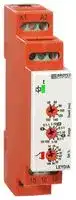
LEYD/A 12-230V AC/DC
Analogue Timer, LEYD/A, Star-Delta, 0.1 s, 100 h, 7 Ranges, 1 Changeover Relay
⚠️ Reference pricing provided. In case of supply shortages, we will connect you with our trusted procurement partners to ensure your project's continuity.
- Manufacturer: BROYCE CONTROL
- Product type: Analogue Timers - DIN Rail
- Product Range:LEYD/A Series; Timer Functions:Star-Delta; Time Min:0.1s; Time Max:100h; No. of Timing Ranges:7Ranges; Timer Output:1 Changeover Relay; Supply Voltage Max:230V; Curr
- SVHC: No SVHC (04-Feb-2026)
- Time Max: 100h
- Time Min: 0.1s
- Timer Output: 1 Changeover Relay
- Product Range: LEYD/A
- Timer Functions: Star-Delta
- Current Rating Nom: 6A
- Supply Voltage Max: 230V
- No. of Timing Ranges: 7Ranges
- Connection / Termination: Screw Terminals
| Delivery and price | |
|---|---|
| Units per pack | 10 |
| Price | 46.53 € |
| Current stock | 10+ |
| Lead time | 30 days |
Datasheet

## S CONTROL

## _**Type: LEYD/A**_ **Star/Delta Start Timer**

**==> picture [262 x 20] intentionally omitted <==**

**----- Start of picture text -----**<br>
Terminal Protection  Q *NEW* 17.5mm DIN rail housing<br>to IP20<br>**----- End of picture text -----**<br>


- **Star/Delta timing function**

- **7 Selectable Dwell time settings (40 – 160mS)**

- **7 Selectable time ranges (0.1 seconds – 100 hours)**

**==> picture [84 x 76] intentionally omitted <==**

**----- Start of picture text -----**<br>
idee :<br>Gi<br>2:<br>a 3<br>Dims: to DIN<br>43880<br>W. 17.5mm<br>**----- End of picture text -----**<br>


- **Fine adjustment of selected time range Multi-voltage input (12 – 230V AC/DC) 1 x SPDT relay output 8A**

- **Green LED indication for supply / timing status Red LED indication for relay status Conforms to IEC 61812**

**==> picture [499 x 368] intentionally omitted <==**

**----- Start of picture text -----**<br>
• TECHNICAL SPECIFICATION<br>Supply voltage U  (A1, A2) :  12 – 230V AC/DC<br>Frequency range:  48 - 63Hz (AC supplies)<br>Supply variation:  AC: +15/-10%   DC: +/-15%<br>Overvoltage category:  III (IEC 60664)<br>Supply - jy Power consumption (max.): Rated impulse withstand voltage:  4kV (1.2/5012V  µS) IEC 60664 24V  110V  230V<br>A1, A2 AC:  0.6VA  0.8VA  2.6VA  6.8VA<br>DC:  0.52W  0.48W  0.94W  1.9W<br>Timing function:  Star/Delta Start<br>Selectable Dwell (tdwell)<br> time settings (7):  40, 60, 80, 100, 120, 140, 160ms<br>Output U Hl oryO| :(- Hl Timing ranges (7):  0.1 – 1 Seconds:  0.1 – 1 Minutes:  0.1 – 1 Hours:<br>15 nn 18 1 – 10  1 – 10  10 - 100 1 – 10<br>16<br>s Ce Reset time [2] :  < 100mS<br>t tdwell YDSU0314 Accuracy:  ± 1% of maximum full scale<br>< Adjustment accuracy:  < 5% of maximum full scale<br>vl, Repeat accuracy:  ± 0.5% at constant conditions (IEC 61812)<br>Drift with temperature:  ± 0.05% / °C<br>LED operation: LED Off LED On LED Flashing Drift with voltage:  ± 0.2% / V<br>Power on indication / Timing [1] :  Green LED<br>Relay status  Red LED<br>Ambient temp:  -20 to +60°C<br>Relative humidity:  +95%<br>Installation work must be carried<br>out by qualified personnel. Output  (15, 16, 18) :  SPDT relay<br>Output rating:   AC1  250V 6A (1500VA)<br>DC1  30V 6A (180W)<br>Electrical life:   ≥ 150,000 ops at rated load<br>➎ to the required position.  to the required position.  Dielectric voltage:  2kV AC (rms) IEC 60947-1<br>➍ to the required position (depending on whether seconds, minutes or hours  Rated impulse withstand voltage:  4kV (1.2/50µS) IEC 60664<br>are required), then set the “Set %” adjustment ➌➌ as required. The “Set %” is a % of the selected  Housing:  Orange flame retardant UL94<br>range, so 60% of the 1 – 10 hour range will give 6 hours.  Weight:  ≈ 70g<br>Mounting option:  On to 35mm symmetric DIN rail to BS EN 60715<br>or direct surface mounting via 2 x M3.5 or 4BA screws<br>➊ will start flashing to indicate timing is in progress. Contacts 15  using the black clips provided on the rear of the unit.<br>Terminal conductor size  ≤ 2 x 2.5mm [2]  solid or stranded<br>At the end of the delay period “t”, contacts 15 and 16 will open for the period set by the Dwell  Approvals:  Conforms to IEC 61812.<br>After the Dwell time, contacts 15 and 18 will close and the red relay LED ➋ will illuminate to ➋ will illuminate to  will illuminate to  e(U)us LISTED ND. CONT.111187 EQ.<br>CE, C-tick  ©  and RoHS Compliant.<br>The relay will remain in the energised state until power is removed. Re-applying power will  EMC: Immunity: EN 61000-6-2 (EN 61000-4-3 10V/m<br>80MHz - 2.7GHz)<br>Emissions: EN 61000-6-4<br>**----- End of picture text -----**<br>


**==> picture [88 x 7] intentionally omitted <==**

**----- Start of picture text -----**<br>
• FUNCTION DIAGRAM<br>**----- End of picture text -----**<br>


- _INSTALLATION AND SETTING_

- BEFORE INSTALLATION, ISOLATE THE SUPPLY.

- Connect the unit as required.

_Setting the unit._

- Set the “Dwell (ms)” selector ➎ to the required position.  to the required position.

- Set the “Range” ➍ to the required position (depending on whether seconds, minutes or hours are required), then set the “Set %” adjustment ➌➌ as required. The “Set %” is a % of the selected range, so 60% of the 1 – 10 hour range will give 6 hours.

_Applying power._

- Apply power and the green LED ➊ will start flashing to indicate timing is in progress. Contacts 15 and 16 will remain closed during this period.

- At the end of the delay period “t”, contacts 15 and 16 will open for the period set by the Dwell time.

- After the Dwell time, contacts 15 and 18 will close and the red relay LED ➋ will illuminate to ➋ will illuminate to  will illuminate to indicate the relay is in the energised state.

- The relay will remain in the energised state until power is removed. Re-applying power will repeat the whole process again.

_Note:_

- _1 In accordance with IEC 61812, the green LED is permitted to extinguish during a voltage dip or momentary interruption of the power supply providing the state of the output relay does not change. The dip / interruption duration and levels are defined in the product standard._

- _2 The dip / interruption (reset) duration and levels are defined in the product standard however, the standard allows for these to be different from the levels actually specified._

**==> picture [544 x 133] intentionally omitted <==**

**----- Start of picture text -----**<br>
• ; CONNECTION DIAGRAM • ° SETTING DETAILS  — • ——— DIMENSIONS<br>Sere<br>SupplyN/-veL/+ve A1 A2 1. Power supply status / Timing (Green) LED 2. Relay output status (Red) LED  ➊ t ➎ a 89 (exc. clips)67.545<br>3. “Set %” adjustment<br>selector<br>4. Time delay “Range”  '<br>15 selector 5. “Dwell” time adjustment 0.1-1. 1-10 Insert screwdriverto release clips<br>R ➍<br>16 7 18 40-100 10" ➌<br>YA 10 2,<br>aly Withdraw clips<br>15 16 18 ➋ Pt 7 surface mountingfully when  <<br>LEYD/A le 92 (+/- 1mm) 1<br>all dimensions in mm.<br>66.5<br>49.5<br>29<br>**----- End of picture text -----**<br>


Broyce Control Ltd., Pool Street, Wolverhampton, West Midlands WV2 4HN. England Tel: +44 (0) 1902 773746 Fax: +44 (0) 1902 420639 Email: sales@broycecontrol.com Web: www.broycecontrol.com

_The Information provided in this literature is believed to be accurate (subject to change without prior notice); however, use of such information shall be entirely at the user’s own risk._

LEYD_A-2-A.DOCX 1811
Updated at June 3, 2026
About Novapart
Novapart is a B2B electronic component broker specialising in stock shortages and cost reduction. We source hard-to-find parts and identify compliant alternatives across a catalogue of 410,000+ components from 500+ manufacturers.
Learn more →Stock Shortage Specialist
When a component is unavailable, discontinued or has an unacceptable lead time, we tap into our network of vetted European and Asian distributors to source what you need — without compromising on quality or traceability.
Request a quote →Compliant Alternatives
We identify pin-to-pin, electrically equivalent substitutes that meet the same certifications (RoHS, AEC-Q100, REACH) as your original specification — validated against datasheets, not just part numbers. Often at a lower cost.
BOM Analysis service →