
Image not available
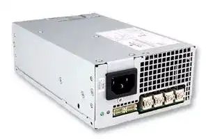
Illustrative purposes only

LCM600L
AC/DC Enclosed Power Supply (PSU), ITE & Medical, 1 Outputs, 600 W, 12 VDC, 52 A
⚠️ Reference pricing provided. In case of supply shortages, we will connect you with our trusted procurement partners to ensure your project's continuity.
- Manufacturer: ARTESYN / ADVANCED ENERGY
- Product type: AC / DC Enclosed Power Supplies
- No. of Outputs:1Outputs; Output Power Max:600W; Output Voltage - Output 1:12V; Output Current - Output 1:52A; Output Voltage - Output 2:-; Output Current - Output 2:-; Output Voltage - Ou
- SVHC: No SVHC (17-Dec-2014)
- Product Range: LCM600 Series
- No. of Outputs: 1Outputs
- Output Power Max: 600W
- Input Voltage VAC: 85V AC to 264V AC
- Input Voltage AC Max: 264V
- Input Voltage AC Min: 85V
- Power Supply Output Type: Adjustable, Fixed
- Output Current - Output 1: 52A
- Output Current - Output 2: -
- Output Current - Output 3: -
- Output Current - Output 4: -
- Output Voltage - Output 1: 12VDC
- Output Voltage - Output 2: -
- Output Voltage - Output 3: -
- Output Voltage - Output 4: -
- Power Supply Applications: ITE & Medical
| Delivery and price | |
|---|---|
| Units per pack | 20 |
| Price | 164.84 € |
| Current stock | 10+ |
| Lead time | 30 days |
Datasheet

## a, POWER :

## **Data Sheet**

## **LCM600** 600 Watt Bulk Front End

**Total Power:** 600 W **# of Outputs:** Single **Outputs:** 12 to 60 V Optional 5.0 V standby

## SPECIAL FEATURES

600 W output power

- Low cost

2.4” x 4.5” x 7.5”

7.41 W/cu-in

- Industrial/Medical safety

- -40 °C to 70 °C with derating

Optional 5 V @ 2 A housekeeping High efficiency: 89% typical Variable speed “Smart Fans”

- DSP controlled front end

- Conformal coat option ± 20% adjustment range

Margin programming

- OR-ing FET

- Terminal block input option

## COMPLIANCE

EMI Class B

- EN61000 Immunity

## SAFETY

- UL 60950-1 1598/1433 60601-1

- CSA 60950-1 VDE 60950-1 60601

- China CCC CB Scheme Report/Cert

## **Electrical Specifications**

## **Input**

|**Electrical Specificationspecificationsecifications**|**Electrical Specificationspecificationsecifications**|
|---|---|
|**Input**||
|Input ra nge|85 - 264 Vac (Operating)<br>115/230 Vac (Nominal) Input through standard IEC connector/<br>TERMINAL BLOCK|
|Frequency|47 - 440 Hz, Nominal 50/60|
|Input fusing|Internal 10 A fuses, both lines fused|
|Inrush current|≤ 25 A peak, either hot or cold start|
|Power factor|0.99 typical, meets EN61000-3-2|
|Harmonics|Meets IEC 1000-3-2 requirements|
|Input current|8 A RMS max input current, at 100 Vac|
|Hold up time|20 ms minimum for Main O/P, at full rated load|
|Efficiency|> 89% at full load|
|Leakage current|< 0.3 mA at 264 Vac|
|ON/OFF power switch|N/A|
|Power line transient|MOV directly after the fuse|
|Isolation|Isolation: PRI-Chassis 2500 Vdc Basic<br>PRI-SEC 4000 VAC Reinforced 2xMOPP<br>SEC-Chassis 500 Vdc|


**==> picture [113 x 7] intentionally omitted <==**

**==> picture [267 x 119] intentionally omitted <==**

**----- Start of picture text -----**<br>
92.00<br>90.00<br>88.00<br>86.00<br>84.00 100 Vac230 Vac<br>82.00<br>80.00<br>78.00<br>76.00<br>25 50 75 100<br>Loading %<br>**----- End of picture text -----**<br>


|**Electrical Specifications**|**Electrical Specifications**|**Electrical Specifications**|
|---|---|---|
|**Output**|||
|Output rating<br>~~SO~~|See orderinginformation table<br>~~SO~~|85 - 264 Vac<br>~~SO~~|
|Setpoint<br>~~SO~~<br>~~a~~|± 0.5%<br>~~SO~~|85 - 264 Vac<br>~~SO~~|
|Total regulation range|Main output ± 2%<br>5 Vsb ± 1%|Combined line/load/transient when measured at output<br>terminal|
|Rated load<br>~~en~~|600 W maximum<br>~~en~~|Derate linear to 50% from 50 °C to 70 °C<br>~~en~~|
|Minimum load<br>~~en~~|Main output @ 0.0 A<br>5 Vsb @ 0.0 A<br>~~en~~|No loss of regulation<br>~~en~~|
|Output noise (PARD)|1% max p-p<br>50 mV max p-p|Main output<br>5 Vsb output<br>Measured with a 0.1 μF Ceramic and 10 μF Tantalum<br>Capacitor on anyoutput, 20 MHz|
|Output voltage overshoot||No overshoot/undershoot outside the regulation band during<br>on or off cycle|
|Transient response|< 300 µSec|50% load step @ 1 A/µs<br>Step load valid between 10% to 100% of output rating<br>Recoverytime to within 1% of setpoint at onset of transient|
|Max units inparallel<br>~~RO~~|~~RO~~|Upto 10<br>~~RO~~|
|Short circuitprotection<br>~~RO~~<br>~~a~~|Protected, no damage to occur<br>~~RO~~<br>~~GG~~|Bounce mode<br>~~RO~~<br>~~GG~~|
|Remote sense<br>~~a~~<br>~~a~~|~~GG~~|Compensation upto 500 mV<br>~~GG~~|
|Output isolation<br>~~en~~|~~en~~|Standardper safetyrequirements<br>~~en~~|
|Forced load sharing<br>~~en~~<br>~~a~~|To within 10% of all shared outputs<br>~~en~~<br>~~a~~|Analogsharingcontrol<br>~~en~~<br>~~a~~|
|Overload protection (OCP)<br>~~a~~|105% to 125%<br>120% to 170%<br>~~a~~|Main output<br>5 Vsb output<br>~~a~~|
|Overvoltage protection (OVP)|125% to 145%<br>110% to 125%|12 V output<br>5 Vsb output|
|Overtemp protection<br>~~a~~|10 - 15 °C above safe operatingarea<br>~~a~~|Both PFC and output converter monitored<br>~~a~~|
|Fan faultprotection<br>~~es~~|~~es~~|For-N option only. Will shutdown output and DC_OK<br>~~es~~|


|**Ordering Information**|**Ordering Information**|**Ordering Information**|**Ordering Information**|**Ordering Information**|**Ordering Information**|**Ordering Information**|**Ordering Information**|**Ordering Information**|**Ordering Information**|
|---|---|---|---|---|---|---|---|---|---|
|Model<br>Number*<br>~~ee~~<br>~~PO~~|Output<br>~~ee~~<br>~~PO~~|Nominal Output<br>Voltage Set Point<br>~~ee~~|Set Point<br>Tolerance|Adjustment Range<br>~~ee~~|Current<br>~~ee~~||Output Ripple<br>P/P (0-50 ˚C)<br>~~ee~~|Max Continuous<br>Power|Combined Line/<br>Load Regulation|
||||||Min<br>~~ee~~|Max<br>~~ee~~||||
|LCM600L<br>~~ee~~<br>~~PO~~<br>~~es~~|12 V<br>~~ee~~<br>~~PO~~<br>~~en~~|12 V<br>~~ee~~<br>~~en~~|±0.5%<br>~~sf~~|9.6 - 14.4 V<br>~~ee~~<br>~~sf~~|0 A<br>~~ee~~<br>~~QQ~~|52 A<br>~~ee~~<br>~~QQ~~|120 mV<br>~~ee~~<br>~~QQ~~|600 W<br>~~(~~|2%|
|LCM600N<br>~~PO~~<br>~~es~~|15 V<br>~~PO~~<br>~~en~~|15 V<br>~~en~~|±0.5%<br>~~sf~~|12.0 - 19.5 V<br>~~sf~~<br>~~(GS~~|0 A<br>~~QQ~~<br>~~(GS~~|44 A<br>~~QQ~~<br>~~(DO~~|150 mV<br>~~QQ~~<br>~~(DO~~|600 W<br>~~(~~<br>~~(OO~~|2%|
|LCM600Q<br>~~es ~~<br>~~Gn~~|24 V<br> ~~en~~<br>~~Gn~~|24 V<br>~~en~~<br>~~Gn~~|±0.5%<br>~~sf~~<br>~~Gn~~|19.2 - 28.8 V<br>~~sf~~<br>~~Gn~~<br>~~(GS~~|0 A<br>~~QQ~~<br>~~Gn~~<br>~~(GS~~|27 A<br>~~QQ~~<br>~~Gn~~<br>~~(DO~~|240 mV<br>~~QQ~~<br>~~Gn~~<br>~~(DO~~|600 W<br>~~(~~<br>~~Gn~~<br>~~(OO~~|2%<br>~~Gn~~|
|LCM600U<br>~~Gn~~<br>~~PO~~<br>~~PO~~|36 V<br>~~Gn~~<br>~~PO~~<br>~~PO~~|36 V<br>~~Gn~~<br>~~PO~~|±0.5%<br>~~Gn~~<br>~~PO~~|28.8 - 43.2 V<br>~~Gn~~<br>~~(GS~~<br>~~PO~~|0 A<br>~~Gn~~<br>~~(GS~~<br>~~PO~~|16.7 A<br>~~Gn~~<br>~~(DO~~<br>~~PO~~|240 mV<br>~~Gn~~<br>~~(DO~~<br>~~PO~~|600 W<br>~~Gn~~<br>~~(OO~~<br>~~PO~~|2%<br>~~Gn~~<br>~~PO~~|
|LCM600W<br>~~PO~~<br>~~PO~~|48 V<br>~~PO~~<br>~~PO~~|48 V<br>~~PO~~|±0.5%<br>~~PO~~|38.4 - 57.6 V<br>~~PO~~|0 A<br>~~PO~~|14 A<br>~~PO~~|280 mV<br>~~PO~~|600 W<br>~~PO~~|2%<br>~~PO~~|


*Note: Add “-T” for terminal block instead of IEC input

Add “-N” for low noise model on 12 V or 24 V models

Add “-4” for 5 V Standby output

Add “-A” will be automatically added to all orders to denote new Aesthetics style chassis unless otherwise specified Example: a 24 V with terminal block, low noise and standby with new Aesthetics would be LCM600Q-T-N-4-A

|**Pin Assignment**<br>~~==~~|**Pin Assignment**<br>~~==~~|**Pin Assignment**<br>~~==~~|
|---|---|---|
|Signals<br>~~Ge~~<br>~~==~~|Name Description<br>~~Ge~~<br>~~==~~|Pin Number(s)<br>~~Ge~~<br>~~==~~|
|+Vout<br>~~a==~~|Power rail<br>~~==~~|SK4<br>~~==~~|
|GND<br>~~a==~~|Power GND<br>~~==~~|SK5<br>~~==~~|
|Signals<br>~~==~~<br>~~a~~<br>~~I~~|Name Description<br>~~==~~|SK2 Pin Number<br>~~==~~|
|A2<br>~~==~~<br>~~a~~<br>~~Ien~~|EEPROM Address<br>~~==~~|1<br>~~==~~|
|-VPROG<br>~~==~~<br>~~Ien~~|Return connection of external supply for Margin Programming<br>~~==~~|2<br>~~==~~|
|A1<br>~~==~~<br>~~en~~<br>~~a~~<br>~~es~~|EEPROM Address<br>~~==~~|3<br>~~==~~|
|-Vsense<br>~~==~~<br>~~a~~<br>~~es~~<br>~~I~~|Remote Sense Return<br>~~==~~|4<br>~~==~~|
|ISHARE<br>~~==~~<br>~~es~~<br>~~I~~<br>~~Se~~|Load share voltage<br>~~==~~|5<br>~~==~~|
|A0<br>~~==~~<br>~~I~~<br>~~Se~~<br>~~I~~|EEPROM Address<br>~~==~~|6<br>~~==~~|
|SDA1<br>~~==~~<br>~~Se~~<br>~~Ia~~|Serial Data Signal (I2C)<br>~~==~~|7<br>~~==~~|
|+VPROG<br>~~==~~<br>~~Ia~~<br>~~Co~~|Positive connection of external supply for Margin Programming<br>~~==~~|8<br>~~==~~|
|SCL1<br>~~==~~<br>~~a~~<br>~~Co~~|Serial Clock Signal (I2C)<br>~~==~~|9<br>~~==~~|
|+Vsense<br>~~==~~<br>~~Coa~~<br>~~I~~|Remote Sense Positive<br>~~==~~|10<br>~~==~~|
|5VSB<br>~~==~~<br>~~a~~<br>~~I~~<br>~~Se~~|5V standby<br>~~==~~|11<br>~~==~~|
|GND<br>~~==~~<br>~~I~~<br>~~Se~~<br>~~I~~|5V standby Return<br>~~==~~<br>|12<br>~~==~~<br>|
|5VSB<br>~~==~~<br>~~Se~~<br>~~I~~|5V standby<br>~~==~~<br>|13<br>~~==~~<br>|
|G_DCOK_C<br>~~==~~<br>~~Ife~~<br>~~I~~|Global DCOK Collector<br>~~==~~<br>~~fe~~|14<br>~~==~~<br>~~fe~~|
|GPIOA6<br>~~==~~<br>~~fe~~<br>~~Ien~~|EEPROM Write Protect<br>~~==~~<br>~~fe~~|15<br>~~==~~<br>~~fe~~|
|G_DCOK_E<br>~~==~~<br>~~Ien~~<br>~~a~~|Global DCOK Emitter (GND)<br>~~==~~|16<br>~~==~~|
|GND<br>~~==~~<br>~~en~~<br>~~aes~~|Return Ground for output signal and I2C communication<br>~~==~~|17<br>~~==~~|
|G_ACOK_C<br>~~==~~<br>~~aes~~<br>~~I~~|Global ACOK Collector<br>~~==~~|18<br>~~==~~|
|INH_EN<br>~~==~~<br>~~es~~<br>~~Ies~~|Turn Off Main Output<br>~~==~~|19<br>~~==~~|
|G_ACOK_E<br>~~==~~<br>~~Ies~~|Global ACOK Emitter (GND)<br>~~==~~|20<br>~~==~~|


Signal Output Signal Connectors (SK2) SK2 Mating Connector: JST Part Number PHDR-20VS; Contact Pins: JST Part Number SPHD-001T-P0.5

## **LED INDICATORS**

2 provided are clearly visible up to a 45 degree offset from vertical with office environment ambient lighting. The status is reflected in the indicator color.

**The DC_OK LED** LED is bicolor. It shall light green if the DC output is within specification, and amber if the output falls out of specification.

**The AC_OK LED** LED is green if the AC is within specification and off when out of specification. Note: With 5 V standby, Amber also indicates that PSU is in standby mode/output off.

## **CONTROL SIGNALS**

**AC_OK** Open collector 0.5 V maximum at 10 mA. Both emitter and collector access provided. **DC_OK** Open collector 0.5 V maximum at 10 mA. Both emitter and collector access provided.

DC_OK will de-assert when output is loss due to OCP, OVP, OTP, or Fan Fault (for -N option). **PS_INHIBIT/ENABLE Signal** 0.0 - 0.5 V contact closure, output OFF

**Ordering Information** LCMXXXXY - A - B - C - ### ~~DP rrt—‘“‘—i—stsSs—sSsrs—SsYS‘C( a ee Cri~~ Case Size Input Termination Acoustic Noise Option Codes Hardware Code 1-Phase input where XXXX = 600 = 2.4” x 4.5” x 7.5”, 600W Blank = IEC connector Blank = Standard Blank = No Options Factory Assigned for Modified standards ~~eS~~ T = Terminal Block N = Low Noise Fan 1 = Conformal Coat ~~PF rrrrt—<“——sSsSs—sSE Cri~~ Voltage Code Y = 4 = 5 V Standby Code 5 = Opt 1 + 4 ~~F —rrr—“<—<~iS dr~~ L 12 ~~FP rrrrrt—“<—~s~~ N 15 ~~PS rrr—<“—;iSrd Te er~~ Q 24 ~~es es ns (rtrd td(dO~~ U 36 ~~Sr d|hrdT~~ W 48 ~~DP rrrti—‘“i—~s [Thr~~ **Mechanical Drawings**

**==> picture [539 x 367] intentionally omitted <==**

**----- Start of picture text -----**<br>
New Mechanical Reference Drawing:<br>(212.2 ref)<br>Weight: 2.84 lbs (1.29 Kg) SEE DETAIL  A (18.5)  190.5 0.5<br>SEE DETAIL C (TRIMPOT LOCATION)<br>MOUNTING LOCATIONS SCREW<br>PENETRATION DEPTH IS 4.6 mm MAX.<br>GROUND<br>RECOMMENDED SCREW TORQUE:<br>M3.5 x 0.6P = 6 - 8kgf-cm<br>NEUTRAL<br>M4.0 x 0.7P = 8 - 10kgf-cm<br>LIVE<br>Note 7 RECOMMENDED SCREW TORQUE:<br>M3.5x0.6P = 6-8kgf-cm<br>M4.0x0.7P = 8-10kfg-cm<br>DETAIL  A<br>Note 8 INPUT: TERMINAL BLOCK TYPE.   SCALE  1.500<br>M3.5 SCREW TORQUE VALUE OF 12kgf-cm   SCREW-MC PHILIP PAN<br>USING WIRE GAUGE 22-19 (9.5mm CENTERS) WITH WASHER M4x8 (8X) MOUNTING LOCATIONS<br>BOTH SIDES<br>SEE DETAIL B BRAND LOGO M4X0.7P THREAD<br>INPUT TERMINAL BLOCK SEE NOTE 7<br>SEE NOTE 8<br>LED (AC OK) SK4 & SK5 (2X)6 0.5 (2X)10.6 50<br>(2X)182.5 0.5<br>LED (DC/OK FAIL)<br>CONNECTOR - 20WAYSK2 SIGNAL (2X)177.5 0.5<br>(2X)10 0.5<br>VOLTAGE ADJUSTMENT:<br>CLOCKWISE - INCREASE VOLTAGE<br>COUNTER CLOCKWISE - DECREASE VOLTAGE<br>DETAIL C<br>(TRIMPOT LOCATION)<br>(4X) MOUNTING LOCATIONS<br>M4X0.7P THREAD<br>— ! ‘ “ SEE NOTE 7<br>AC INLET VERSIONDETAIL B ey<br>16.8<br>9.5<br>9.5<br>0.5<br>114.3<br>1<br>50<br>62<br>41<br>0.5 0.5<br>(2X)47 (2X)22<br>0.5<br>0.5 0.5<br>11.15<br>(2X) 94.45 17.65<br>**----- End of picture text -----**<br>


NOTE: OPTIONAL BARRIER STRIP OUTPUT TERMINAL AVAILABLE OPTIONAL MOLEX TYPE CONNECTOR OUTPUT AVAILABLE

## **Mechanical Drawings – Terminal Block Input**

## **Old Mechanical Reference Drawing:**

**==> picture [481 x 327] intentionally omitted <==**

**----- Start of picture text -----**<br>
Weight: 2.84 lbs (1.29 Kg) SEE DETAIL  A 190,5 0,5<br>Note 7 RECOMMENDED SCREW TORQUE: 18,5 REF SEE DETAIL B (TRIMPOT LOCATION)<br>M3.5x0.6P = 6-8kgf-cm nn ooo [2<br>M4.0x0.7P = 8-10kfg-cm<br>ac 5 1<br>GROUND<br>' it io) NUETRAL e<br>oO —— LIVE<br>' di A<br>=| ©<br>DETAIL  A<br>ry SCALE  8:5<br>SCREW-MC PHILIP PAN<br>INPUT TERMINAL BLOCKSEE NOTE 8 WITH EXT-T WASHERM3.5 x P0.6 x 6 PRODUCT LABEL PROVISION FOR FUTURELABEL REQUIREMENTS<br>(8X) MOUNTING LOCATIONS<br>BOTH SIDES<br>= eef=)2 ralealan uieaal| iealed))=ENN \y7—-LY e 0 oy M4X0.7P THREADSEE NOTE 7 P T E RE<br>LED (DC/OK FAIL) i= LIA R i 4 ! i aX X<br>LED (AC OK) vot& GE ——a es Ness eos 4 en ee a L eeS2<br>ba<br>POS - SK4 (2X)6 0,5 (2X)10,6 50<br>NEG - SK5 (2X)182,5 0,5<br>SK2 SIGNAL CONNECTOR - 20WAY (2X)177,5 0,5<br>(2X)10 0,5<br>rt a r J<br>q fe) PS) b |<br>of i Oo [ ;<br>VOLTAGE ADJUSTMENT:<br>CLOCKWISE - INCREASE VOLTAGE (4X) MOUNTING LOCATIONS<br>COUNTER CLOCKWISE - DECREASE VOLTAGE M4X0.7P THREAD<br>SEE NOTE 7<br>DETAIL B Md©) )<br>(TRIMPOT LOCATION)<br>16,8<br>9,5<br>9,5<br>0,5<br>114,3<br>12,8<br>32,8<br>0,5 0,5<br>61 (2X)47 40,2<br>0,5 15,75<br>(2X)22<br>0,5 0,5<br>0,5 11,15<br>17,65<br>(2X)94,45<br>**----- End of picture text -----**<br>


## **Low Noise VS Non-Low Noise LCM600 Model** ~~Lo~~

**==> picture [519 x 282] intentionally omitted <==**

**----- Start of picture text -----**<br>
60.0<br>58.0 25 Deg Ambient NON-Low noise version<br>56.0 Low noise version<br>54.0<br>52.050.048.046.0 eeee4<br>44.042.040.0 ———Dfell<br>38.036.0 eeer<br>34.0<br>32.0<br>30.0<br>0 2.5 5 7.5 10 12.5 15 17.5 20 22.5 25 27.5 30 32.5 35 37.5 40 42.5 45 47.5 50<br>LOAD (A)<br>60.0<br>58.0 50 Deg Ambient<br>56.0<br>54.0<br>52.050.048.046.044.0 el eeaoee<br>A<br>42.0<br>40.0 NON-Low noise version<br>38.0 eee Low noise version oe<br>36.0 lll —<br>34.0<br>32.0<br>30.0<br>0 2.5 5 7.5 10 12.5 15 17.5 20 22.5 25 27.5 30 32.5 35 37.5 40 42.5 45 47.5 50<br>LOAD (A)<br>NOISE (dBA<br>NOISE (dBA<br>**----- End of picture text -----**<br>


|**NON-Low noise version**<br>**Low noise version**|
|---|
|LOAD (A)<br>25˚C ambient<br>50˚C ambient<br>fan (V)<br>RPM<br>noise (dbA)<br>fan (V)<br>RPM<br>noise (dbA)<br>0<br>6.254<br>3558.0<br>40.9<br>6.228<br>3460.9<br>39.9<br>2.5<br>6.257<br>3559.8<br>41.0<br>6.228<br>3460.9<br>39.9<br>5<br>6.262<br>3562.0<br>41.0<br>6.230<br>3494.3<br>40.1<br>7.5<br>6.263<br>3562.0<br>41.0<br>6.242<br>3526.6<br>40.1<br>10<br>6.242<br>3528.9<br>40.5<br>6.242<br>3526.6<br>40.1<br>12.5<br>6.251<br>3530.9<br>40.6<br>6.237<br>3515.6<br>40.4<br>15<br>6.251<br>3538.3<br>40.7<br>6.229<br>3504.9<br>40.2<br>17.5<br>6.226<br>3538.2<br>40.7<br>6.205<br>3482.8<br>39.4<br>20<br>6.223<br>3541.0<br>40.7<br>6.217<br>3490.1<br>40.0<br>22.5<br>6.242<br>3545.1<br>40.8<br>6.227<br>3493.8<br>40.1<br>25<br>6.253<br>3553.9<br>40.9<br>6.234<br>3504.3<br>40.2<br>27.5<br>6.254<br>3564.1<br>41.0<br>6.212<br>3501.7<br>40.2<br>30<br>6.253<br>3552.2<br>40.9<br>6.642<br>3787.4<br>44.1<br>32.5<br>6.264<br>3559.7<br>41.0<br>7.893<br>4652.3<br>48.0<br>35<br>6.262<br>3559.6<br>41.0<br>9.153<br>5463.4<br>50.0<br>37.5<br>6.262<br>3560.8<br>41.0<br>11.035<br>6600.2<br>52.0<br>40<br>6.262<br>3559.8<br>41.0<br>11.605<br>6993.9<br>53.2<br>42.5<br>7.637<br>4521.2<br>47.8<br>11.608<br>6997.2<br>53.2<br>45<br>8.919<br>5362.2<br>49.3<br>11.608<br>6997.2<br>53.2<br>47.5<br>10.068<br>6139.5<br>51.0<br>11.608<br>6997.2<br>53.2<br>50<br>11.362<br>6893.4<br>52.8<br>11.608<br>6997.2<br>53.2<br>PWM<br>25˚C ambient<br>50˚C ambient<br>LOAD (A)<br>RPM<br>noise (dbA)<br>LOAD (A)<br>RPM<br>noise (dbA)<br>0%<br>0<br>3028<br>35.2<br>0<br>3180<br>36.0<br>5%<br>2.5<br>3028<br>35.2<br>2.5<br>3300<br>36.7<br>10%<br>5<br>3028<br>35.2<br>5<br>3300<br>36.7<br>15%<br>7.5<br>3060<br>35.4<br>7.5<br>3360<br>37.0<br>20%<br>10<br>3028<br>35.2<br>10<br>3360<br>37.0<br>25%<br>12.5<br>3028<br>35.2<br>12.5<br>3360<br>37.0<br>30%<br>15<br>3060<br>35.4<br>15<br>3360<br>37.0<br>35%<br>17.5<br>3060<br>35.4<br>17.5<br>3388<br>37.2<br>40%<br>20<br>3028<br>35.2<br>20<br>3388<br>37.2<br>45%<br>22.5<br>3028<br>35.2<br>22.5<br>3540<br>38.0<br>50%<br>25<br>3060<br>35.4<br>25<br>3840<br>39.2<br>55%<br>27.5<br>3028<br>35.2<br>27.5<br>4104<br>40.2<br>60%<br>30<br>3028<br>35.2<br>30<br>4408<br>41.4<br>65%<br>32.5<br>3060<br>35.4<br>32.5<br>4736<br>42.7<br>70%<br>35<br>3060<br>35.4<br>35<br>5184<br>44.5<br>75%<br>37.5<br>3060<br>35.4<br>37.5<br>5728<br>46.4<br>80%<br>40<br>3060<br>35.4<br>40<br>6688<br>49.5<br>85%<br>42.5<br>3420<br>37.4<br>42.5<br>7560<br>51.8<br>90%<br>45<br>3868<br>39.3<br>45<br>7584<br>51.9<br>95%<br>47.5<br>4376<br>41.3<br>47.5<br>7584<br>51.9<br>100%<br>50<br>5040<br>43.9<br>50<br>7584<br>51.9<br>~~pp~~<br>~~0 eee eee~~<br>~~a~~<br>~~ee~~<br>~~pot CU~~<br>~~eG~~<br>~~eG~~<br>~~sOGD~~<br>~~poo~~<br>~~ee~~<br>~~Ge GC~~<br>~~OeGGG~~<br>~~pot~~<br>~~pooS|~~<br>~~poo~~<br>~~eG~~<br>~~eG~~<br>~~OG~~<br>~~eG~~<br>~~po~~<br>~~poofCT~~<br>~~poo~~<br>~~eG~~<br>~~eG~~<br>~~OsGG~~<br>~~poo~~<br>~~poofCT~~<br>~~po~~<br>~~a~~<br>~~eG~~<br>~~eG~~<br>~~OsGO~~<br>~~pooCT~~<br>~~pooS|~~<br>~~pot~~<br>~~a~~<br>~~eG~~<br>~~eG~~<br>~~OsGG~~<br>~~po~~|


## **Accessories**

**==> picture [254 x 64] intentionally omitted <==**

**----- Start of picture text -----**<br>
PIN 20 PIN 19<br>[jmqe 8H —CG<br>qe 8 a<br>qeye sli8H C<br>He eff PIN 3 & (—————————<br>PIN 2 PIN 1<br>300 ± 5 mm<br>**----- End of picture text -----**<br>


Order kit part number 73-788-001 for control connector interface with .3m wires attached

**==> picture [99 x 82] intentionally omitted <==**

**----- Start of picture text -----**<br>
PIN 20 PIN 19<br>[os Ba<br>| a<br>[a a]<br>| q<br>ai[|| elloi]a<br>cy q<br>(loa[|= ealia<br>Cy(|e) Beu PIN 3<br>PIN 2 eli PIN 1<br>**----- End of picture text -----**<br>


Order kit part number 73-788-002 for control connector interface with unloaded housing and 20 pins

## **Miscellaneous Specifications**

## **BURN-IN**

100% Burn-in at 45 °C, at 80 - 90 % load. Duration of burn-in determined by Quality Assurance Procedures.

## **MTBF**

The power supply has a minimum MTBF of 300K hours using the Bell core 332, issue 6 specification @ 25 °C and 40 °C, ambient, at full load. With the power supply installed in a system in a 25 °C ambient environment and operating at full load, capacitor life shall be 10 years, minimum for ALL electrolytic capacitors contained within this power supply. The power supply shall demonstrate a MTBF level of > 500,000 hours.

## **QUALITY ASSURANCE**

Full QAV testing shall be conducted in accordance with Artesyn Embedded Technologies Standards with reports available upon request.

## **WARRANTY**

Artesyn Embedded Technologies shall warrant the power supply to be free of defects in materials and workmanship for a minimum period of three years from the date of shipment, when operated within specifications. The warranty shall be fully transferable to the end owner of the equipment powered by the supply.

##

Europe (UK) Asia (HK) Waterfront Business Park 14/F, Lu Plaza Merry Hill, Dudley 2 Wing Yip Street West Midlands, DY5 1LX Kwun Tong, Kowloon United Kingdom Hong Kong +44 (0) 1384 842 211 +852 2176 3333

Americas 2900 S.Diablo Way Tempe, AZ 85282 USA +1 888 412 7832

While every precaution has been taken to ensure accuracy and completeness in this literature, Artesyn Embedded Technologies assumes no responsibility, and disclaims all liability for damages resulting from use of this information or for any errors or omissions. Artesyn Embedded Technologies, Artesyn and the Artesyn Embedded Technologies logo are trademarks and service marks of Artesyn Embedded Technologies, Inc. All other names and logos referred to are trade names, trademarks, or registered trademarks of their respective owners. © 2015 Artesyn Embedded Technologies, Inc.

**www.artesyn.com**

For more information: www.artesyn.com/power For support: productsupport.ep@artesyn.com

LCM600 DS  14May2015
Updated at June 6, 2026
About Novapart
Novapart is a B2B electronic component broker specialising in stock shortages and cost reduction. We source hard-to-find parts and identify compliant alternatives across a catalogue of 410,000+ components from 500+ manufacturers.
Learn more →Stock Shortage Specialist
When a component is unavailable, discontinued or has an unacceptable lead time, we tap into our network of vetted European and Asian distributors to source what you need — without compromising on quality or traceability.
Request a quote →Compliant Alternatives
We identify pin-to-pin, electrically equivalent substitutes that meet the same certifications (RoHS, AEC-Q100, REACH) as your original specification — validated against datasheets, not just part numbers. Often at a lower cost.
BOM Analysis service →