
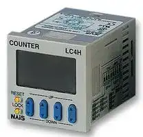


LC4H-R4-AC240VS
Counter, LED, LC4H Series, 4 Digits, 100 to 240 Vac, Screw Terminals
- Manufacturer: PANASONIC
- Product type:
- No. of Digits / Alpha:4; Digit Height:-; Supply Voltage Min:100VAC; Supply Voltage Max:240VAC; Panel Cutout Height:45mm; Panel Cutout Width:45mm; Operating Temperature Min:-10°C; Operating Temperature M
- SVHC: No SVHC (07-Jul-2017)
- Digit Height: -
- Product Range: -
- Panel Cutout Width: 45mm
- Supply Voltage Max: 240VAC
- Supply Voltage Min: 100VAC
- Panel Cutout Height: 45mm
- No. of Digits / Alpha: 4
- Operating Temperature Max: 55°C
- Operating Temperature Min: -10°C
| Delivery and price | |
|---|---|
| Units per pack | 1 |
| Price | 121.11 € |
| Current stock | 10+ |
| Lead time | 30 days |
LC4H/-L

## **DIN 48 SIZE** LC4H/-L **LCD ELECTRONIC COUNTER** Counters a

## **LC4H Counters**

**UL File No.: E122222 C-UL File No.: E122222**

## **Features**

**==> picture [172 x 217] intentionally omitted <==**

**----- Start of picture text -----**<br>
48<br>1.890<br>64.5<br>4-digit display | —St 1.89048 —+ 2.539mm inch<br>6-digit display Satytyt<br>a<br>Pin type Screw terminal type<br>**----- End of picture text -----**<br>


## **1. Bright and Easy-to-Read Display**

A brand new bright 2-color backlight LCD display. The easy-to-read screen in any location makes checking and setting procedures a cinch.

## **2. Simple Operation**

Seesaw buttons make operating the unit even easier than before.

## **3. Short Body of only 64.5 mm 2.539 inch (screw type) or 70.1 mm 2.760 inch (pin type)**

With a short body, it easily installs in even narrow control panels.

## **4. Conforms to IP66’s Weather**

## **Resistant Standards**

The water-proof panel keeps out water and dirt for reliable operation even in poor environments.

## **5. Screw terminal and Pin Type are Both Standard Options**

The two terminal types are standard options to support either front panel installation or embedded installation.

## **6. Changeable Panel Cover**

Also offers a black panel cover to meet your design considerations.

## **7. 4-digit or 6-digit display**

Two sizes of displays are offered for you to choose the one that suits your needs.

## **8. Compliant with UL, c-UL and CE.**

**RoHS Directive compatibility information http://www.nais-e.com/**

## **Product types**

**==> picture [521 x 310] intentionally omitted <==**

**----- Start of picture text -----**<br>
Digit Count speed Output mode Output Operating voltage Power down insurance Terminal type Part number<br>8 pins LC4H8-R4-AC240V<br>100 to 240 V AC 11 pins LC4H-R4-AC240V<br>Screw terminal LC4H-R4-AC240VS<br>Se eT 8 pins LC4H8-R4-AC24V<br>Relay 24 V AC 11 pins LC4H-R4-AC24V<br>(1c) | Screw terminal LC4H-R4-AC24VS<br>—— 8 pins LC4H8-R4-DC24V<br>12 to 24 V DC 11 pins LC4H-R4-DC24V<br>4 | Screw terminal LC4H-R4-DC24VS<br>8 pins LC4H8-T4-AC240V<br>100 to 240 V AC 11 pins LC4H-T4-AC240V<br>• Maintain | —— Screw terminal LC4H-T4-AC240VS<br>• Maintain• Maintainoutput/hold countoutput/over count I Transistor(1a) | 24 V AC —— Screw terminal11 pins8 pins8 pins LC4H8-T4-DC24VLC4H8-T4-AC24VLC4H-T4-AC24VLC4H-T4-AC24VS<br>5 KHz (Kcps)30 Hz (cps)/switchable • One shot/overoutput/over count count II | 12 to 24 V DC Available —— Screw terminal11 pins8 pins LC4H-T4-DC24VLC4H-T4-DC24VSLC4H8-R6-AC240V<br>• One shot/recount I 100 to 240 V AC 11 pins LC4H-R6-AC240V<br>• One shot/recount II | —— Screw terminal LC4H-R6-AC240VS<br>• One shot/holdcount Relay(1c) | 24 V AC —— Screw terminal11 pins8 pins LC4H8-R6-AC24VLC4H-R6-AC24VLC4H-R6-AC24VS<br>(7 modes) 8 pins LC4H8-R6-DC24V<br>12 to 24 V DC 11 pins LC4H-R6-DC24V<br>6 | —— Screw terminal LC4H-R6-DC24VS<br>8 pins LC4H8-T6-AC240V<br>100 to 240 V AC 11 pins LC4H-T6-AC240V<br>| —— Screw terminal LC4H-T6-AC240VS<br>Transistor 8 pins LC4H8-T6-AC24V<br>24 V AC 11 pins LC4H-T6-AC24V<br>(1a) | —— Screw terminal LC4H-T6-AC24VS<br>8 pins LC4H8-T6-DC24V<br>12 to 24 V DC 11 pins LC4H-T6-DC24V<br>| —— Screw terminal LC4H-T6-DC24VS<br>* A rubber gasket (ATC18002) and a mounting frame (AT8-DA4) are included.<br>**----- End of picture text -----**<br>


All Rights Reserved © C OPYRIGHT Matsushita Electric Works, Ltd.

LC4H/-L

## **LC4H-L Counters**

**==> picture [138 x 289] intentionally omitted <==**

**----- Start of picture text -----**<br>
1.89048 (234<br>|essain’<br>64.5<br>48 2.539<br>I 1.890 _|<br>mm inch<br>AEL11 Series<br>(4-digit display)<br>123456<br>ning . a ® .<br>AEL13 Series<br>(6-digit display)<br>Pin type Screw terminal type<br>**----- End of picture text -----**<br>


**UL File No.: E122222 C-UL File No.: E122222**

## **Features**

## **1. Low Price**

All this at an affordable price to provide you with unmatched cost performance.

**2. Display is a bright reflective-type LCD.**

**3. Inherits all of the characteristics of the LC4H digital timer.**

- Seesaw switches ensure easy operation.

- IP66 environmental protection.

- Shortened body (pin type: 70.1 mm 2.760 inch, screw type: 64.5 mm 2.539 inch underhead).

**4. Compliant with UL, c-UL and CE.**

## **Product types**

**==> picture [510 x 301] intentionally omitted <==**

**----- Start of picture text -----**<br>
Digit (es Count speed Output mode (er Output Operating voltage rs QO Power down insurance Terminal type Part number<br>8 pins LC4HL8-R4-AC240V<br>100 to 240 V AC 11 pins LC4HL-R4-AC240V<br>Screw terminal LC4HL-R4-AC240VS<br>8 pins LC4HL8-R4-AC24V<br>Relay 24 V AC/DC 11 pins LC4HL-R4-AC24V<br>(1c) Screw terminal LC4HL-R4-AC24VS<br>8 pins LC4HL8-R4-DC24V<br>12 to 24 V DC 11 pins LC4HL-R4-DC24V<br>4 = | — Screw terminal LC4HL-R4-DC24VS<br>8 pins LC4HL8-T4-AC240V<br>100 to 240 V AC 11 pins LC4HL-T4-AC240V<br>• Maintain | Screw terminal LC4HL-T4-AC240VS<br>• Maintain• Maintainoutput/hold countoutput/over count I Transistor(1a) 24 V AC/DC — Screw terminal11 pins8 pins8 pins LC4HL8-T4-DC24VLC4HL8-T4-AC24VLC4HL-T4-AC24VLC4HL-T4-AC24VS<br>5 KHz (Kcps)30 Hz (cps)/switchable • One shot/overoutput/over count count II =| 12 to 24 V DC Available — Screw terminal11 pins8 pins LC4HL-T4-DC24VLC4HL-T4-DC24VSLC4HL8-R6-AC240V<br>• One shot/recount I 100 to 240 V AC 11 pins LC4HL-R6-AC240V<br>• One shot/recount II | Screw terminal LC4HL-R6-AC240VS<br>• One shot/holdcount Relay(1c) 24 V AC/DC — Screw terminal11 pins8 pins LC4HL8-R6-AC24VLC4HL-R6-AC24VLC4HL-R6-AC24VS<br>(7 modes) 8 pins LC4HL8-R6-DC24V<br>12 to 24 V DC 11 pins LC4HL-R6-DC24V<br>6 =| — Screw terminal LC4HL-R6-DC24VS<br>8 pins LC4HL8-T6-AC240V<br>100 to 240 V AC 11 pins LC4HL-T6-AC240V<br>|— Screw terminal LC4HL-T6-AC240VS<br>Transistor 8 pins LC4HL8-T6-AC24V<br>24 V AC/DC 11 pins LC4HL-T6-AC24V<br>(1a) Screw terminal LC4HL-T6-AC24VS<br>8 pins LC4HL8-T6-DC24V<br>12 to 24 V DC 11 pins LC4HL-T6-DC24V<br>| —— Screw terminal LC4HL-T6-DC24VS<br>**----- End of picture text -----**<br>


* A rubber gasket (ATC18002) and a mounting frame (AT8-DA4) are included.

All Rights Reserved © C OPYRIGHT Matsushita Electric Works, Ltd.

LC4H/-L

## **Part names**

**==> picture [448 x 260] intentionally omitted <==**

**----- Start of picture text -----**<br>
DIP switches<br>COUNTER<br>Counter display<br>1 2 3 4 5 6 7 8<br>Controlled output indicator<br>Set value display<br>Reset indicator OP.RST<br>LOCK<br>Lock indicator UP<br>RESET<br>Up keys<br>Reset switch LOCK<br>Down keys<br>Lock switch LC4H DOWN<br>(Same for screw terminal type)<br>DIP switches<br>COUNTER<br>Counter display<br>1 2 3 4 5 6 7 8<br>Controlled output indicator<br>Set value display<br>Reset indicator OP.RST<br>LOCK<br>Lock indicator<br>RESET<br>Up keys<br>Reset switch LOCK<br>Lock switch LC4H<br>(Same for screw terminal type)<br>ON<br>ON<br>**----- End of picture text -----**<br>


## **• 4-digit display type**

## **• 6-digit display type**

## **Specifications**

||Item|Item|Ralay output type|Ralay output type|Transistor output type|Transistor output type|
|---|---|---|---|---|---|---|
||||AC type|DC type|AC type|DC type|
|Rating|100 to<br>Rated operating voltage||240 V AC, 24 V AC|12 to 24 V DC|100 to 240 V AC, 24 V AC|12 to 24 V DC|
||50<br>Rated frequency||/60 Hz common|—|50/60 Hz common|—|
||Rated power consumption||Max. 10 V A|Max. 3 W|Max. 10 V A|Max. 3 W|
||Rated control capacity||5 A 250 V AC (resistive load)||100 mA 30 V DC||
||Input mode||Addition (UP)/Subtraction (DOWN)/Direction (DIR)/Individuality (IND)/Phase (PHASE)<br>5 modes selectable by DIP switch||||
||Max. counting speed||30 Hz/5 kHz (selectable by DIP switch)||||
||Counting input (Input 1, 2)||Min. input signal width: 16.7 ms at 30 Hz/0.1 ms at 5 kHz, ON time: OFF time = 1:1||||
||Reset input||Min. input signal width: 1 ms, 20 ms (selected by DIP switch)||||
||Lock input||Min. input signal width: 20 ms||||
||Input signal||Contact or Open collector input/Input impedance: 1 kΩor less, Input residual voltage: 2 V or less,<br>Open impedance: 100 kΩor more, Max. energized voltage: 40 V DC||||
||Output mode||HOLD-A/HOLD-B/HOLD-C/SHOT-A/SHOT-B/SHOT-C/SHOT-D (7 modes selectable by DIP switch)||||
||One shot output time||Approx. 1 s||||
||Indication||7-segment LCD, Counter value (backlight red LED), Setting value (backlight yellow LED)||||
||Digit||4-digit display type –999 to 9999 (–3 digits to +4 digits) (0 to 9999 for setting)<br>6-digit display type –99999 to 999999 (–5 digits to 6 digits) (0 to 999999 for setting)||||
||Memory||EEP-ROM (Overwriting times: 105 ope. or more)||||
|Contact|Contact arrangement||1 Form C||1 Form A (Open collector)||
||Initial contact resistance||100 mΩ(at 1 A 6 V DC)||—||
||Contact material||Ag alloy/Au flush||—||
|Life|2<br>Mechanical (contact)||×107 ope. (Except for switch operation parts)||—||
||Electrical (contact)||105 ope. (At rated control voltage)||107 ope. (At rated control voltage)||
|Electrical|Allowable operating voltage range||85 to 110 % of rated operating voltage||||
||Between l<br>B<br> <br>Break down voltage<br>(Initial value)||ive and dead metal parts: 2,000 Vrms for 1 min (11-pin type)<br>etween input and output: 2,000 Vrms for 1 min<br>Between open contacts: 1,000 Vrms for 1 min||Between live and dead metal parts: 2,000 Vrms for 1 min (11-pin type)<br>Between input and output: 2,000 V AC for 1 min||
||Between<br>Insulation resistance<br>(At 500 V DC) (Initial<br>value)||live and dead metal parts: Min. 100 MΩ(11-pin type)<br>Between input and output: Min. 100 MΩ<br>Between open contact: Min. 100 MΩ||Between live and dead metal parts: Min. 100 MΩ(11-pin type)<br>Between input and output: Min. 100 MΩ||
||Max. 65°<br>Temperature rise||C (under the flow of nominal operating current at nominal voltage)||||
|Mechanical|Vibration<br>resistance|Functional|10 to 55 Hz (1 cycle/min), single amplitude: 0.35 mm (10 min on 3 axes)||||
|||Destructive|10 to 55 Hz (1 cycle/min), single amplitude: 0.75 mm (1 h on 3 axes)||||
||Shock<br>resistance|Functional|Min. 98 m321.522 ft./s2 (4 times on 3 axes)||||
|||Destructive|Min. 294 m964.567 ft./s2 (5 times on 3 axes)||||
|Operating<br>conditions|Ambient temperature||–10° C to 55° C+14° F to +131° F||||
||Ambient humidity||Max. 85 % RH (non-condensing)||||
||Air pressure||860 to 1,060 h Pa||||
||Ripple rate||—|20 % or less|—|20 % or less|
|Connection|||8-pin/11-pin/screw terminal||||
|Protective construction|||IP66 (front panel with a rubber gasket)||||


All Rights Reserved © C OPYRIGHT Matsushita Electric Works, Ltd.

LC4H/-L

## **Applicable standard**

|Safety standard|EN61812-1|Pollution Degree 2/Overvoltage Category II|
|---|---|---|
||(EMI)EN61000-6-4||
||Radiation interference electric field strength|EN55011 Group1 ClassA|
||Noise terminal voltage|EN55011 Group1 ClassA|
||(EMS)EN61000-6-2||
||Static discharge immunity|EN61000-4-2    4 kV contact|
|||8 kV air|
||RF electromagnetic field immunity|EN61000-4-3    10 V/m AM modulation (80 MHz to 1 GHz)|
|||10 V/m pulse modulation (895 MHz to 905 MHz)|
|EMC|EFT/B immunity|EN61000-4-4    2 kV (power supply line)|
|||1 kV (signal line)|
||Surge immunity|EN61000-4-5    1 kV (power line)|
||Conductivity noise immunity|EN61000-4-6    10 V/m AM modulation (0.15 MHz to 80 MHz)|
||Power frequency magnetic field immunity|EN61000-4-8    30 A/m (50 Hz)|
||Voltage dip/Instantaneous stop/Voltage fluctuation immunity|EN61000-4-11  10 ms, 30% (rated voltage)|
|||100 ms, 60% (rated voltage)|
|||1,000 ms, 60% (rated voltage)|
|||5,000 ms, 95% (rated voltage)|


## **Dimensions**

## **• 4-digit display type**

mm inch General tolerance: ±1.0 ±.039

**==> picture [516 x 148] intentionally omitted <==**

**----- Start of picture text -----**<br>
Screw terminal type: M3.5  Pin type<br>(Flush mount) (Flush mount/Surface mount)<br>1.89048 5.5.217 64.5 5.5.217 2.76070.155.6<br>2.539 2.189<br>COUNTER<br>1.89048 OP.LOCKRST ((44.51.752 ((44.51.752<br>RESET UP<br>LOCK<br>LC4H DOWN 7.5 7.5<br>.295 .295<br>**----- End of picture text -----**<br>


## **• 6-digit display type**

**==> picture [517 x 147] intentionally omitted <==**

**----- Start of picture text -----**<br>
Screw terminal type: M3.5  Pin type<br>(Flush mount) (Flush mount/Surface mount)<br>1.89048 5.5.216 2.53964.5 5.5.217 2.7602.18970.155.6<br>COUNTER<br>1.89048 OP.LOCKRST ((44.51.752 ((44.51.752<br>RESET<br>LOCK<br>LC4H 7.5 7.5<br>.295 .295<br>**----- End of picture text -----**<br>


All Rights Reserved © C OPYRIGHT Matsushita Electric Works, Ltd.

LC4H/-L

## **• Dimensions for flush mounting (with adapter installed)**

Screw terminal type: M3.5

**==> picture [529 x 380] intentionally omitted <==**

**----- Start of picture text -----**<br>
Screw terminal type: M3.5 Pin type<br>Rubber gasketATC18002 (supplied) Panel Mounting frame for flush mount Rubber gasketATC18002 (supplied) Panel Mounting frame for flush mount 8-pin type(8p cap AD8-RC<br>AT8-DA4 (supplied) AT8-DA4  sold separately)<br>(supplied) 11-pin type<br>COUNTER COUNTER (11p cap AT8-DP11<br>sold separately)<br>48 OP.RST 50 (44.5 48 OP.RST 50<br>1.890 LOCK 1.969 66 (1.752 1.890 LOCK 1.969<br>RESET UP 2.598 RESET<br>LOCK LOCK<br>LC4H DOWN LC4H<br>1 1<br>48 .039 63.5 48 .039 90<br>1.890 2.500 1.890 3.543<br>• Dimensions for front panel installations • Installation panel cut-out dimensions • For connected installations<br>The standard panel cut-out dimensions are shown<br>DIN rail terminal block8-pin type: AT8-DF8K  below. Use the mounting frame (AT8-DA4) and<br>(sold separately) rubber gasket (ATC18002). 45 [-0.6] 0<br>11-pin type: AT8-DF11K  80 min. 1.772 [-.024] 0<br>(sold separately) 3.150<br>45 [-0.6] 0 1.772 [-.024] 0<br>Device installation rail A<br>AT8-DLA1 (sold separately) 1.77245 [-.024][-0.6] 00 A = (48 × n – 2.5)  [–0.6] 0<br>80 min.<br>95.5 3.150 Note 1: The installation panel thickness should be between 1<br>3.760(90.0) and 5 mm .039 and .197 inch.<br>(3.543) Note 2: For connected installations, the waterproofing ability<br>(   ) Dimensions for 8-pin type. between the unit and installation panel is lost.<br>Terminal layouts and Wiring diagrams<br>• 8-pin type • 11-pin type • Screw terminal type<br>Relay output type Transistor output type Relay output type Transistor output type Relay output type Transistor output type<br>Input 2Input 1Reset 32 41 58 67 Input 2Input 1Reset 32 41 58 67 NO ResetInput 1Input 2Lock 3425 1 611107 89 NCNO ResetInput 1Input 2Lock 3425 1 611107 89 ResetInput 1Input 2Lock 6 7 8 9 10 NCNO ResetInput 1Input 2Lock 6 7 8 9 10<br>~– Operatingvoltage ~+ ~– Operatingvoltage ~+ ~– Operatingvoltage ~+ ~– Operatingvoltage ~+ 1 2 3 4 5 1 2 3 4 5<br>~+ Operatingvoltage ~– ~+ Operatingvoltage ~–<br>66<br>**----- End of picture text -----**<br>


Note) For connecting the output leads of the transistor output type, refer to 5) Transistor output on page 141.

All Rights Reserved © C OPYRIGHT Matsushita Electric Works, Ltd.

LC4H/-L

## **Setting the operation mode and set value**

## **Setting procedure 1)  Setting the operation mode (input mode and output mode)**

Set the input and output modes with the DIP switches on the side of the counter. **DIP switches**

Table 1: Setting the output mode

**==> picture [435 x 219] intentionally omitted <==**

**----- Start of picture text -----**<br>
DIP switch DIP switch No.<br>Item Output mode<br>OFF ON 1 2 3<br>1 ON ON ON SHOT-A<br>2 Output mode Refer to table 1 OFF OFF OFF SHOT-B<br>3 ON OFF OFF SHOT-C<br>4 Minimum reset input signal width 20 ms 1 ms OFF ON OFF SHOT-D<br>5 Maximum counter speed 30 Hz 5 kHz ON ON OFF HOLD-A<br>6 OFF OFF ON HOLD-B<br>7 Input mode Refer to table 2 ON OFF ON HOLD-C<br>8 OFF ON ON — (See note 1)<br>Table 2: Setting the input mode<br>DIP switch No.<br>DIP switches (See note 2) Input mode<br>6 7 8<br>1 2 3 4 5 6 7 8 ON ON ON Addition input<br>OFF OFF OFF Subtraction input<br>ON OFF OFF Directive input<br>OFF ON OFF Independent input<br>ON ON OFF Phase input<br>OFF OFF ON — (See note 1)<br>(Same for 6-digit and screw terminal types)<br>ON OFF ON — (See note 1)<br>OFF ON ON — (See note 1)<br>ON<br>**----- End of picture text -----**<br>


## **Setting procedure 2)  Setting the set value**

Notes:1) The counter and set value displays will display DIP Err. Notes:2) Set the DIP switches before installing the counter on the panel. Notes:3) When the DIP SW setting is changed, turn off the power once. Notes:4) The DIP switches are set as ON before shipping.

Set the set value with the UP and DOWN keys on the front of the counter. **Front display section**

## **• 4-digit display type**

**==> picture [298 x 205] intentionally omitted <==**

**----- Start of picture text -----**<br>
Q Counter display COUNTER 1<br>W Set value display 3<br>E Controlled output indicator OP. 2<br>R Reset indicator 4 RSTLOCK<br>T Lock indicator 5 UP 6<br>Y UP keys 8 RESET 7<br>Changes the corresponding 9 LOCK<br>digit of the set value in the LC4H DOWN<br>addition direction (upwards).<br>• 6-digit display type COUNTER<br>Q Counter display 1<br>W Set value display 3<br>2<br>E Controlled output indicator 4 OP.RST<br>R Reset indicator LOCK<br>T Lock indicator 5 6<br>RESET<br>7<br>LOCK<br>8<br>LC4H<br>**----- End of picture text -----**<br>


## **• Changing the set value**

2) Suppose that the counter is preset to count down. Whether a preset countdown value is smaller or larger than the count value, the counter counts down to “0(Zero)”.

## **1. It is possible to change the set value with the up and down keys (4digit type only) even during counting. However, be aware of the following points.**

1) If the set value is changed to less than the count value with counting set to the addition direction, counting will continue until it reaches full scale (9999 with the 4-digit type and 999999 with the 6-digit type), returns to zero, and then reaches the new set value. If the set value is changed to a value above the count value, counting will continue until the count value reaches the new set value.

## **2. If the set value is changed to “0,” the unit will not complete count-up. It starts counting up when the counting value comes to “0 (Zero)” again.**

1) Up-count (addition) input when counting is set to the addition direction, counting will continue until full scale is reached (9999 with the 4-digit type and 999999 with the 6-digit type), return to zero, and then complete count-up.

## U DOWN keys

   - Changes the corresponding digit of the set value in the subtraction direction (downwards).

- I RESET switch

   - Resets the counting value and the output.

- O LOCK switch Locks the operation of all keys on the counter.

## Y UP keys

Changes the corresponding digit of the set value in the addition direction (upwards).

- U RESET switch Resets the counting value and the output.

- I LOCK switch

Locks the operation of all keys on the counter.

2) Down-count (subtraction) input when counting is set to the subtraction direction, counting will continue until full scale is reached (-999 with the 4-digit type and -99999 with the 6-digit type), and then the display will change to with the 4-digit type and with the 6-digit type. The counting value does not become “0” and so the counter does not count up.

3) For directive, independent, and phase input, when the counting value increases or decreases from the value "0" and then returns back to the value "0," count-up is completed.

All Rights Reserved © C OPYRIGHT Matsushita Electric Works, Ltd.

LC4H/-L

## **Operation modes**

## **1. Input mode**

For the input mode, you can choose one of the following five modes

|**Operation modes**<br>**1. Input mode**<br>For the input mode, you can choose one of the following five modes|**Operation modes**<br>**1. Input mode**<br>For the input mode, you can choose one of the following five modes|**Operation modes**<br>**1. Input mode**<br>For the input mode, you can choose one of the following five modes|**Operation modes**<br>**1. Input mode**<br>For the input mode, you can choose one of the following five modes|**Operation modes**<br>**1. Input mode**<br>For the input mode, you can choose one of the following five modes|**Operation modes**<br>**1. Input mode**<br>For the input mode, you can choose one of the following five modes|**Operation modes**<br>**1. Input mode**<br>For the input mode, you can choose one of the following five modes|**Operation modes**<br>**1. Input mode**<br>For the input mode, you can choose one of the following five modes|**Operation modes**<br>**1. Input mode**<br>For the input mode, you can choose one of the following five modes|**Operation modes**<br>**1. Input mode**<br>For the input mode, you can choose one of the following five modes|**Operation modes**<br>**1. Input mode**<br>For the input mode, you can choose one of the following five modes|**Operation modes**<br>**1. Input mode**<br>For the input mode, you can choose one of the following five modes|**Operation modes**<br>**1. Input mode**<br>For the input mode, you can choose one of the following five modes|**Operation modes**<br>**1. Input mode**<br>For the input mode, you can choose one of the following five modes|**Operation modes**<br>**1. Input mode**<br>For the input mode, you can choose one of the following five modes|**Operation modes**<br>**1. Input mode**<br>For the input mode, you can choose one of the following five modes|**Operation modes**<br>**1. Input mode**<br>For the input mode, you can choose one of the following five modes|**Operation modes**<br>**1. Input mode**<br>For the input mode, you can choose one of the following five modes|
|---|---|---|---|---|---|---|---|---|---|---|---|---|---|---|---|---|---|
|• Addition<br>• Subtraction<br>• Directive<br>• Independent<br>• Phase<br>PHASE<br>IND<br>DIR<br>DOWN<br>UP||||||||||||||||||
|Input mode|Operation|*Minimum input signal width 30 Hz: 16.7 ms; 5 kHz: 0.1 ms||||||||||||||||
|Addition<br>UP|IN1 or IN2 works as an input block<br>(gate) for the other input.|• Example where IN1 is the count counting and I<br>• Example where IN2 is the counting input and IN<br>* “A” must be more than the minimum input signa<br>0<br>1<br>2<br>3<br>n<br>n-1<br>n-2<br>n-3<br>H<br>L<br>H<br>L<br>IN1<br>IN2<br>Counting (subtraction)<br>Counting (addition)<br>Blocked<br>A<br>A<br>A A<br>Reset<br>A<br>A<br>A <br>n<br>n-1<br>n-2<br>n-3<br>0<br>1<br>2<br>3<br>H<br>L<br>H<br>L<br>IN1<br>IN2<br>Counting (subtraction)<br>Counting (addition)<br>Blocked<br>Blocked<br>Reset||||||counting and I<br>cked<br>A A|||N2 is the input block (gate).<br>1 is the input block (gate).<br>l width.<br>n-3<br>n-2<br>n-1<br>n<br>3<br>2<br>1<br>0<br>Count-up completed<br> A<br>n-4<br>0<br>1<br>4<br>n<br>n-1<br>Count-up completed|||||||
|||||||||||||||||||
|||||||A|A|A||||||||||
||||||||Blo|cked||||||||||
|||||||||||||||||||
|||||||||||||||||||
|||||0||1|2||3|||n-3|n-2||n-1|n||
|||||||||||||||||||
|||||n|n|-1|n-2||n-3|||3|2||1|0||
|Subtraction<br>DOWN||||||||||||||||||
|||||||||||||||||||
||||||||||A<br>A<br>A||A|||||||
|||||||||||||||||||
|||||||||||||||||||
|||||0|||1|2|3||4|||n-||n<br>1||
|||||||||||||||||||
|||||n|||n-1|n-2|n-3||n-4|||1||0<br>||
||||||||||||l width.|||||||
|Directive<br>DIR|IN1 is the counting input and IN2 is the<br>addition or subtraction directive input.<br>IN2 adds at L level and subtracts at H<br>level.|* “A” must be m<br>H<br>L<br>H<br>L<br>Counting<br>IN1<br>IN2||||||||||||Addition<br><br>2<br>3<br>4||||
|||||Addition||||A|Subtract<br>A||ion<br>A A|A A||||||
|||||||||||||||||||
|||||||||||||||||||
||||ore than the minimum input signa<br>0<br>1<br>2<br>3<br>4<br>3<br>2<br>Reset|||||||||||||||
|||||0|1<br>2|||3<br>4|3|2|1|0|1||2|3|4|
||||||||||||l width.|||||||
|Independent<br>IND|IN1 is addition input and IN2 is subtrac-<br>tion input.|* IN1 and IN2 ar<br>timing.<br>Counting<br>IN1<br>IN2<br>H<br>L<br>H<br>L||||||||||||||||
|||||||||||||||||||
|||||||||||||||||||
|||||||||||||||||||
|||||0|1<br>2||3<br>4||3|2|1|||2|1<br>2|3||
|Phase<br>PHASE|Addition when the IN1 phase advances<br>beyond IN2, and subtraction when the<br>IN2 phase advances beyond IN1.|* “B” must be m<br>Counting<br>IN1<br>IN2<br>H<br>L<br>H<br>L||||||||||||||||
|||||||||||||||||||
|||||||||||||||||||
||||Phase advanc||||B B<br>e|B B||||||||||


All Rights Reserved © C OPYRIGHT Matsushita Electric Works, Ltd.

## LC4H/-L

## **2. Output mode**

For the output mode, you can choose one of the following seven modes

|**2. Output mode**<br>For the output mode, you can choose one of the following seven modes|**2. Output mode**<br>For the output mode, you can choose one of the following seven modes|**2. Output mode**<br>For the output mode, you can choose one of the following seven modes|**2. Output mode**<br>For the output mode, you can choose one of the following seven modes|**2. Output mode**<br>For the output mode, you can choose one of the following seven modes|**2. Output mode**<br>For the output mode, you can choose one of the following seven modes|**2. Output mode**<br>For the output mode, you can choose one of the following seven modes|**2. Output mode**<br>For the output mode, you can choose one of the following seven modes|**2. Output mode**<br>For the output mode, you can choose one of the following seven modes|||
|---|---|---|---|---|---|---|---|---|---|---|
|• Maintain output/hold count<br>• Maintain output/over countI<br>• Maintain output/over countII<br>• One shot/over count<br>• One shot/recountI<br>• One shot/recountII<br>• One shot/hold count<br>SHOT-D<br>SHOT-C<br>SHOT-B<br>SHOT-A<br>HOLD-C<br>HOLD-B<br>HOLD-A|||||||||||
|Output mode|Operation|(Example when input mode is either addition o|||||||r subtraction)||
|Maintain output<br>Hold count<br>HOLD-A|Output control is maintained after<br>count-up completion and until resetting.<br>During that time, the count display does<br>not change from that at count-up com-<br>pletion.|* n: Set value<br>Counting (addition)<br>Counting (subtraction)<br>Counting able/unable<br>Output control<br>O|||||||||
||||||n-3|n-2|n-1||n||
||||||||||||
||||||3|2|1||0||
|||||Able|||||Unable||
||||O|FF||||ON|||
||||||||||||
||||||||||||
|Maintain output<br>Over countI<br>HOLD-B|Output control is maintained after<br>count-up completion and until resetting.<br>However, counting is possible despite<br>completion of count-up.|* n: Set value<br>Counting (addition)<br>Counting (subtraction)<br>Counting able/unable<br>Output control|||||||||
||||||n-2|n-1|n|n+1|n+2||
||||||||||||
||||||2|1|0|-1|-2||
||||||||Able||||
||||O|FF|||ON||||
||||||||||||
||||||||||||
|Maintain output<br>Over countII<br>HOLD-C|Output control is maintained after<br>count-up completion and until the next<br>signal enters. However, counting is<br>possible despite completion of count-<br>up.|* n: Set value<br>Counting (addition)<br>Counting (subtraction)<br>Counting able/unable<br>Output control|||||||||
||||||n-2|n-1|n|n+1|n+2||
||||||||||||
||||||2|1|0|-1|-2||
||||||||Able||||
||||O|FF|||ON|OFF|||
||||||||||||
||||||||||||
|One shot<br>Over count<br>SHOT-A|Output control is maintained after<br>count-up completion for a fixed time<br>(approx. 1 sec). Counting is possible<br>despite completion of count-up.|* n: Set value<br>Counting (addition)<br>Counting (subtraction)<br>Counting able/unable<br>Output control|||||||||
||||||n-2|n-1|n|n+1|n+2||
||||||||||||
||||||2|1|0|-1|-2||
||||||||Able||||
||||O|FF|||ON||OFF||
||||||||||||
|||||Approx. 1s|||Approx. 1s||||
|One shot<br>RecountI<br>SHOT-B|Output control is maintained after<br>count-up completion for a fixed time<br>(approx. 1 sec). Counting is possible<br>despite completion of count-up.<br>However, reset occurs simultaneous<br>with completion of count-up. While out-<br>put is being maintained, restarting of<br>the count is not possible|* n: Set value<br>Counting (addition)<br>Counting (subtraction)<br>Counting able/unable<br>Output control|||n-2|n-1|0|1|2||
||||||||||||
||||||2|1|n|n-1|n-2||
|||||Reset (automatic)<br>Able|||||||
||||O|FF|||ON||OFF||
||||||||||||
|||||Approx. 1s|||||||
|One shot<br>RecountII<br>SHOT-C|Output control is maintained after<br>count-up completion for a fixed time<br>(approx. 1 sec). Counting is possible<br>despite completion of count-up.<br>However, reset occurs simultaneous<br>with output OFF.|* n: Set value<br>Counting (addition)<br>Counting (subtraction)<br>Counting able/unable<br>Output control||n-1<br>n<br>n+1||||0|1||
||||||||||||
||||||1|0|-1|n|n-1||
|||||Able||||Reset (automatic)|||
||||O|FF<br>ON||||OFF|||
||||||||||||
|||||Approx. 1s|||||||
|One shot<br>Hold count<br>SHOT-D|Output control is maintained after<br>count-up completion for a fixed time<br>(approx. 1 sec). During that time, the<br>count display does not change from<br>that at count-up completion. Reset<br>occurs simultaneous with output OFF.|* n: Set value<br>Counting (addition)<br>Counting (subtraction)<br>Counting able/unable<br>Output control||n-1<br>n||||1<br>0|||
||||||||||||
||||||1|0||n|n-1||
|||||Able||Unable||Reset (automatic)<br>Able|||
||||O|FF||ON||OFF|||
||||||||||||
|||||Approx. 1s||Approx. 1s|||||


All Rights Reserved © C OPYRIGHT Matsushita Electric Works, Ltd.
Updated at April 22, 2026
Panasonic Industry is a global leader in the design and manufacture of high-quality electronic components. Renowned for a commitment to continuous innovation, the company provides the essential building blocks that empower modern engineering. From industrial automation to consumer electronics, Panasonic's components are trusted worldwide for their outstanding reliability, efficiency, and long-term performance. The extensive portfolio is anchored by a massive selection of passive components, featuring an industry-leading range of aluminium electrolytic, film, and polymer capacitors. Alongside these advanced capacitance solutions, engineers rely on Panasonic's robust power inductors and a highly versatile array of electromechanical devices, including solid-state, power, and signal relays engineered to excel in demanding environments. Beyond core passives and switching solutions, the offering encompasses critical circuit protection devices such as TVS varistors and NTC thermistors, as well as sophisticated thermal management materials. Panasonic also delivers precision light and motion sensors, highly reliable batteries, and advanced Bluetooth and WLAN connectivity modules, providing a comprehensive ecosystem of components to support next-generation technological design.
About Novapart
Novapart is a B2B electronic component broker specialising in stock shortages and cost reduction. We source hard-to-find parts and identify compliant alternatives across a catalogue of 410,000+ components from 500+ manufacturers.
Learn more →Stock Shortage Specialist
When a component is unavailable, discontinued or has an unacceptable lead time, we tap into our network of vetted European and Asian distributors to source what you need — without compromising on quality or traceability.
Request a quote →Compliant Alternatives
We identify pin-to-pin, electrically equivalent substitutes that meet the same certifications (RoHS, AEC-Q100, REACH) as your original specification — validated against datasheets, not just part numbers. Often at a lower cost.
BOM Analysis service →