


LC2HFFV30J
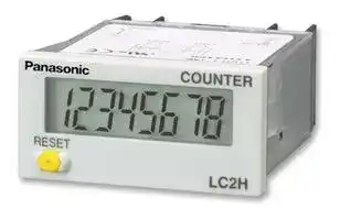
Counter, LCD, LC2H Series, 8 Digits, 24 to 240 Vac/dc, 30 Hz, Front Reset
- Manufacturer: PANASONIC
- Product type:
- No. of Digits / Alpha:8; Digit Height:8.7mm; Supply Voltage Min:24V; Supply Voltage Max:240V; Panel Cutout Height:22.2mm; Panel Cutout Width:45mm; Operating Temperature Min:-10°C; Operating
- SVHC: No SVHC (23-Jan-2024)
- Digit Height: 8.7mm
- Product Range: -
- Panel Cutout Width: 45mm
- Supply Voltage Max: 240V
- Supply Voltage Min: 24V
- Panel Cutout Height: 22.2mm
- No. of Digits / Alpha: 8
- Operating Temperature Max: 55°C
- Operating Temperature Min: -10°C
| Delivery and price | |
|---|---|
| Units per pack | 10 |
| Price | 74.65 € |
| Current stock | 10+ |
| Lead time | 30 days |
LC2H

## **DIN HALF SIZE LCD COUNTER**

## LC2H

## **Features**

Panel mounting type One-touch installation type

Panel mounting type Installation frame type

PC board mounting type

## **1. 8.7 mm .343 inch Character Height (previously 7 mm)**

Easy-to-read character height increased from 7 mm to 8.7 mm .276 inch to .343 inch.

.343inch

## **2. Plenty of Digits** (Lt CAL Ut —( ~~IIE~~ 8 digits —|IW

## **3. Counting Speed Switchable between 2 kHz and 30 Hz**

## **4. Panel Mounting Type Features 2 Installation Methods**

Comes with very easy one-touch installation type and also installation frame type that uses the bracket on the timer/counter. Choose a method that suits the application.

## **5. Battery Replacement Easy on Envi-**

## **ronment**

To replace battery simply remove body for the one-touch installation type, and remove battery lid for the installation frame type.

## **6. Screw Terminals Designed for Safety**

Built in finger protection.

## **7. Panel Covers Replacable (Standard color is ash gray.)**

Change the panel design by replacing with a black panel cover.

## **8. Conforms to IP66 Protective Con-**

## **struction (Only installation frame type.) (Front panel surface)**

## **9. Input Methods**

1) Non-voltage input method

## 2) Voltage input method

## 3) Free voltage input method

## **10. Backlight Type Added to Series and**

## **Now 2-color Switchable (green/red)**

Easy viewing even in dark places and switchable between green and red (Voltage input type).

## **11. Conforms to Safety Regulations**

## **Product chart**

||Standard type<br>~~ee~~|Standard type<br>~~ee~~|Standard type<br>~~ee~~|
|---|---|---|---|
||Non-voltage input type<br>~~ee~~<br>ee|Non-voltage input type<br>Voltage input type<br>(4.5 to 30 V DC)<br>~~ee~~<br>eeee|Free voltage input type<br>(24 to 240 V AC/DC)|
|One-touch installation type<br>~~ee~~<br>~~a~~<br>ee|~~ee~~<br>ee<br>ae|~~ee~~<br>eeee<br>aeee|ee<br>ee|
|Installation frame type<br>~~a~~<br>ee|ee<br>ae|ee ee<br>aeee<br>es|ee<br>ee<br>es|
||ae<br>oe|—<br>ae ee<br>oe<br>es|—<br>ee<br>ee<br>oe<br>es|


## **Product types**

## **1. Panel mounting type**

## 1) One-touch installation type

## 1 Standard type

|Counting speed|Front reset|Input method|
|---|---|---|
|2 kHz/30 Hz switchable|Yes|Non-voltage input type|
|||Voltage input type (4.5 to 30 V DC)|
|30 Hz||Free voltage input type (24 to 240 V AC/DC)|


Note) Please ask us about types without front resetting.

## 2 Backlight type

|Counting speed|Front reset|Input method|
|---|---|---|
|2 kHz/30 Hz switchable|Yes|Voltage input type (4.5 to 30 V DC)|


68

02/2003 02/2003

LC2H

|||||LC2H|
|---|---|---|---|---|
|2) Installation frame type<br>1Standard type|||||
|No. digits|Counting speed|Front reset|Input method|Part No.|
|8 digits|2 kHz/30 Hz switchable|Yes|Non-voltage input type|LC2H-F-2KK|
||||Voltage input type (4.5 to 30 V DC)|LC2H-F-DL-2KK|
||30 Hz||Free voltage input type (24 to 240 V AC/DC)|LC2H-F-FV-30|
|Note) Please ask u|s about types without front resetting.||||
|2Backlight type|||||
|No. digits|Counting speed|Front reset|Input method|Part No.|
|8 digits|2 kHz/30 Hz switchable|Yes|Voltage input type (4.5 to 30 V DC)|LC2H-F-DL-2KK-B|
|**2. PC board mounting type**|||||
|No. digits|Counting speed|Front reset|Input method|Part No.|
|8 digits|2 kHz|No|Non-voltage input type|LC2H-C-2K-N|
||30 Hz|||LC2H-C-30-N|


**Specifications 1. Panel mounting type**

|Type|Type|Standard type|Standard type|Backlight type|Standard type|
|---|---|---|---|---|---|
|Item||Non-voltage input|Voltage input||Free voltage type|
|No. digits||8 digits||||
|External power supply||Not required (built-in battery)||||
|Max. counting speed||2 kHz/30 Hz (Switchable by switch)|||30 Hz (Note 2)|
|Count<br>input|Min. input signal width<br>(ON: OFF = 1:1)|0.25 ms/16.7 ms (Switchable by switch)|||16.7 ms|
||Input method (signal)|Non-voltage input using<br>contacts or open collector<br>connection|High level: 4.5 to 30 V DC<br>Low level: 0 to 2 V DC||High level:<br>24 to 240 V AC/DC<br>Low level:<br>0 to 2.4 V AC/DC|
||Input impedance|When shorted:<br>Max. 10 k<br>When open:<br>Max. 750 k|Approx. 4.7 k||—|
||Residual voltage|Max. 0.5 V|—||—|
|Reset<br>input|Min. input signal width|200 ms||||
||Input method (signal)|Non-voltage input using<br>contacts or open collector<br>connection|High level: 4.5 to 30 V DC<br>Low level: 0 to 2 V DC||Non-voltage input using<br>contacts or open collector<br>connection|
||Input impedance|When shorted:<br>Max. 10 k<br>When open:<br>Max. 750 k|Appox. 4.7 k||When shorted:<br>Max. 10 k<br>When open:<br>Max. 750 k|
||Residual voltage|Max 0.5 V|—||Max. 0.5 V|
|Display|method|7-segment LCD||7-segment LCD<br>With green/red backlight|7-segment LCD|
|Breakdown voltage (initial)||Between charged and uncharged parts: 1,000 V AC for 1 minute.|||Between charged and<br>uncharged parts: 2,000 V<br>AC for 1 minute.|
|Insulation resistance (initial)||Min. 100 M  (measured at 500 V DC) Measurement location same as for break down voltage.||||
|Backlight power||—||24 V DC (±10%)|—|
|Protective construction (Note 3)||IEC Standard IP66 (only panel front: when using rubber gasket)||||
|Accessories (Note 3)||Rubber gasket, mounting bracket||||
|Battery life||7 years (at 25°C77°F) Note 1|||6 years (at 25°C77°F)|


Notes) 1. The value given for battery life is calculated based on continuous operation (count input signal ON/OFF = 1:1), therefore, this value is not guaranteed. Also, battery life is decreased 30% when operation is continuous with 2 kHz count inputting in 2 kHz mode. 2. Operation is at 25 Hz when using 24 V AC.

3. Only for installation frame type.

69

02/2003

LC2H

## **2. PC board mounting type**

|Type|Type|Type|PC board mounting type|PC board mounting type|
|---|---|---|---|---|
|Item|||||
|Input method|||Non DC voltage input||
|No. digits|||8 digits||
|Rated operation voltage|||3 V DC||
|Allowable operation voltage range|||2.7 to 3.3 V DC||
|Current consumption|||Max. 30 µA (max. 250 µA during reset input)||
|Max. counting speed|||2 kHz|30 Hz|
|Count<br>input|Min. input signal width<br>(ON: OFF = 1:1)||0.25 ms|16.7 ms|
||Input method||Non-voltage input using contacts or open collector connection||
||Input impedance||When shorted: Max. 10 k<br>When open: Max. 750 k||
||Residual voltage||Max. 0.5 V||
|Reset<br>input|Min. input signal width||10 ms||
||Input method||Non-voltage input using contacts or open collector connection||
||Input impedance||When shorted: Max. 10 k<br>When open: Max. 750 k||
||Residual power||Max. 0.5 V||
|Break down voltage (initial)|||Between charged and uncharged parts: 1,000 V AC for 1 minute.||
|Insulation resistance (initial)|||Min. 100 M  (measured at 500 V DC) Measurement location same as for break down voltage.||
|**3. Common**|||||
|||Type|Panel mounting/PC board mounting types||
|Item|||||
|Vibration resistance||Functional|10 to 55 Hz (1 cycle/min.), single amplitude: 0.15 mm.006 inch(10 min. on 3 axes)||
|||Destructive|10 to 55 Hz (1 cycle/min.), single amplitude: 0.375 mm.015 inch(1 hr. on 3 axes)||
|Shock resistance||Functional|Min. 98 m/s2(4 times on 3 axes)||
|||Destructive|Min. 294 m/s2(5 times on 3 axes)||
|Operation temperature|||–10 to +55°C+14 to +131°F(without frost or dew)||
|Storage temperature|||–25 to +65°C–13 to +149°F(without frost or dew)||
|Ambient humidity|||35 to 85% RH||


## **Part names**

## **1. Front reset button**

This button resets the count value. It does not work when the lock switch is ON. Be aware that battery life will decrease if this switch is used frequently.

**2. Lock switch (Refer to chart on right.)** Disable the front reset button.

Note)Turn ON at the LCD side (reset disabled) and OFF at the terminal block side (reset enabled).

**3. Count speed switch (Refer to chart on right.)**

Use this switch to switch the count speed between 30 Hz and 2 kHz. (On the nonvoltage and voltage input types, 30 Hz is on the LCD side and 2 kHz is on the terminal block side. Fixed at 30 Hz for free voltage input type.)

Note)You must press the front reset button when you change the count speed switch setting.

**==> picture [347 x 263] intentionally omitted <==**

**----- Start of picture text -----**<br>
COUNTER LC2H Count speed switch<br>RESET<br>Front reset button<br>Lock switch<br>Non-voltage input/voltage input Free voltage input<br>(Terminal block side) OFF❇<br>Lock switch<br>(Unit display 1)<br>(LCD side) ON<br>(Terminal block side) 2k Hz<br>Count speed switch —<br>(Unit display 2)<br>(LCD side) 30Hz❇ (Fixed at 30 Hz)<br>**----- End of picture text -----**<br>


Notes) 1. ❇Default setting when shipped.

2. Make the switch setting before installing to panel.

70

02/2003

LC2H

## **Dimensions**

## **1. Panel mounting type**

mm inch

General tolerance: ±1.0 ±.039

**• External dimensions**

## 1) One-touch installation type

**==> picture [218 x 288] intentionally omitted <==**

**----- Start of picture text -----**<br>
44.8<br>1.764<br>54.4<br>2.142<br>10.4 (44) 5 48<br>.409 (1.732) .197 1.890<br>COUNTER LC2H<br>22 24<br>.866 .945 RESET<br>7<br>.276 Reset button<br>• Panel installation diagram<br>Panel (1 to 4.5mm<br>.039 to .177inch Rubber spacer<br>thickness)<br>**----- End of picture text -----**<br>


## **• Panel installation diagram**

Note)When installing to a 4.5 mm .177 inch thick panel, remove the rubber spacer first.

## 2) Installation frame type

**==> picture [218 x 187] intentionally omitted <==**

**----- Start of picture text -----**<br>
44.8<br>1.764<br>54.4<br>2.142<br>10.4 44 5 48<br>.409 1.732 .197 1.890<br>COUNTER LC2H<br>22 24<br>.866 .945 RESET<br>7<br>.276 Reset button<br>**----- End of picture text -----**<br>


## **• Panel installation diagram**

**==> picture [198 x 100] intentionally omitted <==**

**----- Start of picture text -----**<br>
Installation screws Mounting bracket<br>(found on mounting bracket) ATH3803 (included)<br>37<br>1.457<br>Rubber gasket<br>Panel ATH3804 (included)<br>(1 to 4.5mm .039 to .177inch thickness)<br>**----- End of picture text -----**<br>


## **• Panel cut-out dimensions**

The standard panel cut-out is shown below.

Use the mounting bracket (ATH3803) and the rubber packing (ATH3804). (Only mounting bracket installation type.)

**==> picture [122 x 96] intentionally omitted <==**

**----- Start of picture text -----**<br>
60 min.<br>2.362 min. 1.77245++0.50.0200<br>22.2.874++0.50.0200<br>**----- End of picture text -----**<br>


## **• When installing repeatedly (sealed installation) (Only mounting bracket installation type.)**

**==> picture [118 x 59] intentionally omitted <==**

**----- Start of picture text -----**<br>
22.2.874++0.50.0200<br>A<br>A=(1.890A=(48××n-2.5)n-.098)+1.00 +.0390<br>**----- End of picture text -----**<br>


Notes) 1. Suitable installation panel thickness is 1 to 4.5 mm .039 to .177 inch. 2. Waterproofing will be lost when installing repeatedly (sealed installation).

## **• Terminal layout and wiring diagrams**

## 1) Standard type

**==> picture [528 x 83] intentionally omitted <==**

**----- Start of picture text -----**<br>
Non voltage input type Voltage input type Free voltage input type<br>Count input Reset input Count input Reset input Count input Reset input<br>+V +V<br>1 2 3 4 1 2 3 4 or 1 2 3 4<br>0V 0V<br>Q-R are connected internally.-R are connected internally.R are connected internally. are connected internally.<br>**----- End of picture text -----**<br>


71

02/2003

LC2H

## 2) Backlight type

**==> picture [352 x 95] intentionally omitted <==**

**----- Start of picture text -----**<br>
Voltage input type<br>Backlight<br><When green> <When red><br>0V +V<br>Count input Reset input<br>+V +V<br>5 5 5<br>1 2 3 4 1 2 3 4 1 2 3 4<br>6 6 6<br>0V 0V<br>0V +V<br>**----- End of picture text -----**<br>


**==> picture [506 x 228] intentionally omitted <==**

**----- Start of picture text -----**<br>
2. PC board mounting type General tolerance: ±1.0 ±.039 mm inch<br>33.02 [±][0.3  ] PC board pattern (BOTTOM VIEW)<br>5.08 [±][0.3  ] 1.300 [±][.012] 5.08 [±][0.3]<br>.200 [±][.012] .200 [±][.012] 2.54 Mounting area<br>0.6 [±][0.1  ] .100 1.9<br>.024 [±][.004] DIP switch × 8 .075<br>2.54<br>3.3 [±][0.3  ] .100 15.24 Connection sockets<br>.130 [±][.012] 8-0.8 dia. .600 28 pin DIP terminal<br>8-.031 dia.<br>1.70943.4 17.3.681 0.5.020 [±][0.3][±][.012] 5.08.200 5.19.204 .0751.9<br>5.19 5.08<br>.204 .200<br>19 15.24 [±][0.3] 33.02<br>LC2H .748 .600 [±][.012] 1.300<br>COUNTER<br>  0.3 [±][0.1  ]<br>.012 [±][.004]<br>• Terminal layout and wiring diagrams<br>15 17 26 28<br>Count input Reset input<br>14 12 3 1<br>**----- End of picture text -----**<br>


## **2. PC board mounting type**

## **• External dimensions**

## **• Terminal layout and wiring diagrams**

Q-E, }-w, e-t and S-F are connected internally.

## **Input method**

## **1. Standard type**

**==> picture [528 x 104] intentionally omitted <==**

**----- Start of picture text -----**<br>
Non-voltage input type<br>Panel mounting type PC board mounting type<br>Transistor input Transistor input<br>Contact input Contact input<br>NPN transistor NPN transistor<br>Countinput 1 2 3 4 Resetinput Countinput 1 2 3 4 Resetinput Countinput 1514 1217 263 281 Resetinput Countinput 1514 1217 263 281 Resetinput<br>0V 0V<br>(W and R are connected internally.) (W and R are connected internally.) 3V DC 3V DC<br>**----- End of picture text -----**<br>


- Notes) 1. When using contact input, since current flow is small from terminals 1 and 3 on the panel mounting type and terminals e to t and S to F on the PC board mounting type, please use relays and switches with high contact reliability.

   2. When using transistor input, use the following as a guide for which transistors (Tr) to use for inputting. (Collector withstand voltage Q 50 V, leakage current < 1 µA)

**==> picture [528 x 102] intentionally omitted <==**

**----- Start of picture text -----**<br>
Voltage input type<br>Transistor input Free voltage input type<br>Contact input<br>NPN transistor PNP transistor<br>+V +V<br>+V +V<br>Count Reset<br>input 1 2 3 4 input Countinput 1 2 3 4 Resetinput Countinput 1 2 3 4 Resetinput 1 2 3 4<br>Count input or or or Reset input<br>**----- End of picture text -----**<br>


Notes) 1. 2 and 4. (The input and reset circuits are functionally insulated.)

2. When using transistor (Tr) input, use the right as a guide. (Collector withstand voltage Q 50 V, leakage current < 1 µA)

3. Be aware that the application of voltage that exceeds the voltage range of the H level to the count input terminal, and the application of voltage to the reset input terminal, can cause damage to the internal elements.

72

02/2003

LC2H

## **2. Backlight type**

**==> picture [528 x 102] intentionally omitted <==**

**----- Start of picture text -----**<br>
Voltage input type<br>Transistor input Backlight connection<br>Contact input<br>NPN transistor PNP transistor<br>+V +V +V +V Green Red<br>Count Reset 24V DC<br>input input<br>1 2 56 3 4 Countinput 1 2 56 3 4 Resetinput Countinput 1 2 56 3 4 Resetinput 1 2 56 3 4 1 2 56 3 4<br>0V 0V 24V DC<br>**----- End of picture text -----**<br>


- Notes) 1. Do not reverse the polarities when connecting the DC voltage for the backlight.

   2. 2 and 4. (The input and reset circuits are functionally insulated.)

   3. When using transistor (Tr) input, use the right as a guide. (Collector withstand voltage Q 50 V, leakage current < 1 µA)

   4. Be aware that the application of voltage that exceeds the voltage range of the H level to the count input terminal, and the application of voltage to the reset input terminal, can cause damage to the internal elements.

## **Explanation of operation**

1. Counting takes place when the count input signal is ON.

2. Counting resumes again when the count value reaches 99999999 (full scale value) and then returns to “0” with a new count input.

3. No measurement takes place when a reset is input.

**==> picture [282 x 47] intentionally omitted <==**

**----- Start of picture text -----**<br>
Count input<br>Reset input ❇<br>Count value 0 1 99999999 0 1 0 1<br>**----- End of picture text -----**<br>


Note) ❇Count becomes “1” when the reset input is turned OFF while the count signal is being input.

- 1) When reset is ON, resetting takes place and the count becomes “0”.

- 2) Press the front reset button when you want to reset manually (only panel installation type).

Note)Be aware that battery life will decrease if the count input or reset input are left ON.

## **Cautions for use**

## **1. Non-voltage input type For both panel mounting and PC board mounting types**

1) Never apply voltage to the non-voltage input type. This will damage the internal elements. Also, since there is a possibility of erroneous operation, do not connect in parallel the inputs of a non-voltage input type and another counter from a single input signal.

2) Since the current flow is very small from the count input and reset input terminals (1 and 3 on the panel mounting type and terminals e to t and S to F on the PC board mounting type) please use relays and switches with high contact reliability.

3) When inputting with an open collector of a transistor, use a transistor for small signals in which ICBO is 1 µA or less and always input with no voltage.

4) When wiring, try to keep all the input lines to the count and reset inputs as short as possible and avoid running them together with high voltage and power transmission lines or in a power conduit. Also, malfunctions might occur if the floating capacitance of these wires exceeds 500 pF (10 m 32.808 ft. for parallel wires of 2

mm[2] ). When using 2 kHz mode, use with a wiring floating capacitance of 120 pF (3 m 9.843 ft. for parallel wires of 2 mm[2] ). In particular, when using shielded wiring, be careful of the capacitance between wires.

## **PC board mounting type**

1) For external power supply use manganese dioxide or lithium batteries (CR type: 3V).

2) Always reset after external power is applied and confirm that the display reads “0”.

3) Make the wiring from the battery to the counter unit as short as absolutely possible. Also, be careful of polarity.

- 4) Calculate battery life with the following formula.

t = A/I

- t: battery life [h]

- I: LC2H current consumption [mA]

- A: battery capacity until minimum operation voltage is reached

[mAh]

5) Hand solder to the lead terminal. Do not dip solder. With the tip of the soldering iron at 300°C 572°F perform soldering within 3 seconds (for 30 to 60 W soldering iron).

## **2. Voltage input type**

- 1) Be aware that applying more than 30 V

DC to count input terminals 1 and 2, and reset input terminals 3 and 4 will cause damage to the internal elements.

2) For external resetting use H level (application of 4.5 to 30 V DC) between reset terminals 3 and 4 of the rear terminals. In this case, connect + to terminal 3 and – to terminal 4. This is the valid polarity; therefore, the counter will not work if reversed.

3) When wiring, try to keep all the input lines to the count and reset inputs as short as possible and avoid running them together with high voltage and power transmission lines or in a power conduit. Also, malfunctions might occur if the floating capacitance of these wires exceeds 500 pF (10 m 32.808 ft. for parallel wires of 2 mm[2] ).

## **3. Free voltage input type**

1) Use count input terminals 1 and 2 for free voltage input and reset terminals 3 and 4 for non-voltage input.

2) Be aware that the application of voltage that exceeds the voltage range of the H level to the count input terminal, and the application of voltage to the reset input terminal, can cause damage to the internal elements.

73

02/2003

## LC2H

3) Since the current flow is very small from reset input terminal 3, please use relays and switches with high contact reliability. 4) When inputting a reset with an open collector of a transistor, use a transistor for small signals in which ICBO is 1 µA or less and always input with no voltage.

5) To reset externally, short reset input terminals 3 and 4 on the rear.

6) Input uses a high impedance circuit; therefore, erroneous operation may occur if the influence of induction voltage is present. If you plan to use wiring for the input signal that is 10 m or longer (wire capacitance 120 pF/m at normal temperature), we recommend the use of a CR filter or the connection of a bleeder resistor.

## **4. How to reset multiple panel mounting type counters all at once (input is the same for count) Non-voltage input type**

**==> picture [102 x 29] intentionally omitted <==**

**----- Start of picture text -----**<br>
D D D Tr<br>3 4 3 4 3 4 or<br>**----- End of picture text -----**<br>


Notes) 1. Use the following as a guide for choosing transistors used for input (Tr). Leakage current < 1 µA

2. Use as small a diode (D) as possible in the forward voltage so that the voltage between terminals 3 and 4 during reset input meets the standard value (0.5 V).

- ( At IF = 20 µA, forward voltage 0.1 and higher.)

## **Voltage input type**

**==> picture [133 x 31] intentionally omitted <==**

**----- Start of picture text -----**<br>
+V +V<br>R<br>Tr<br>3 4 3 4 3 4 or 3 4<br>**----- End of picture text -----**<br>


Note)Make sure that H (reset ON) level is at least 4.5 V.

## **5. Backlight luminance**

To prevent varying luminance among backlights when using multiple Backlight types, please use the same backlight power supply.

**==> picture [157 x 39] intentionally omitted <==**

**----- Start of picture text -----**<br>
24V DC 2 5 2 5 2 6 2 6 24V DC<br>Green Red<br>**----- End of picture text -----**<br>


## **6. Insulation sheet**

Before using a panel mounting type, please pull and remove the insulation sheet from the side of the product in the direction of the arrow.

In consideration that the product might be stored for long periods without being used, an insulation sheet is inserted before shipping. Remove the insulation sheet and press the front reset button.

## **One-touch installation type**

**==> picture [106 x 83] intentionally omitted <==**

**----- Start of picture text -----**<br>
Reset button<br>Insulation sheet<br>**----- End of picture text -----**<br>


## **Installation frame type**

**==> picture [106 x 83] intentionally omitted <==**

**----- Start of picture text -----**<br>
Reset button<br>Insulation sheet<br>**----- End of picture text -----**<br>


## **7. Waterproof construction (Installation frame type)**

The operation part of the panel installation type (Installation frame type) is constructed to prevent water from entering the unit and a rubber gasket is provided to prevent water from entering the gap between the unit and the panel cutout. There must be sufficient pressure applied to the rubber gasket to prevent water from entering. Be sure to use the installation reinforcement screws when installing the frame (ATH3803).

Note)The one-touch installation type is not waterproof.

## **8. Do not use in the following environments**

**==> picture [64 x 30] intentionally omitted <==**

**----- Start of picture text -----**<br>
Frame (ATH3803)<br>**----- End of picture text -----**<br>


1) In places where the temperature changes drastically.

2) In places where humidity is high and there is the possibility of dew. (When dew forms the display may vanish and other display errors may occur.)

## **9. Conditions of use**

1) Do not use in places where there is flammable or corrosive gas, lots of dust, presence of oil, or where the unit might be subject to strong vibrations or shocks. 2) Since the cover is made of polycarbonate resin, do not use in places where the unit might come into contact with or be exposed to environments that contain or-

ganic solvents such as methyl alcohol, benzene and thinner, or strong alkali substances such as ammonia and caustic soda.

## **10. Cautions regarding battery replacement**

1) Remove wiring before replacing the battery. You may be electrocuted if you come into contact to a part where high voltage is applied.

2) Make sure you are not carrying a static electric charge when replacing the battery.

- 3) Battery replacement procedure

- 1 One-touch installation type

1. Using a tool remove the up/down hook of the case.

2. Pull the unit away from the case.

3. Remove the battery from the side of the unit. Do not touch the display or other parts.

4. Before inserting wipe clean the surface of the battery.

5. Insert the battery with the + and – sides in the proper position.

6. After replacing the battery return the unit to the case. Verify that the hook of the case has properly engaged.

7. Before using press the reset button on the front.

**==> picture [128 x 328] intentionally omitted <==**

**----- Start of picture text -----**<br>
Tool<br>1<br>2<br>1<br>3<br>6<br>7<br>**----- End of picture text -----**<br>


74

02/2003

LC2H

- 2 Installation frame type

1. Remove the battery cover 1 from the case.

2. Remove the battery 2 from the side of the case. The battery will come loose if you put the battery side face down and lightly shake the unit

3. Before inserting wipe clean the surface of the battery.

4. Insert the battery with the + and – sides in the proper position.

5. After replacing the battery return the battery cover to the case 5. Verify that the hook of the battery cover is properly engaged.

6. Before using press the reset button 6 on the front.

**==> picture [134 x 285] intentionally omitted <==**

**----- Start of picture text -----**<br>
1<br>2<br>+ side<br>5<br>− side<br>6<br>**----- End of picture text -----**<br>


## **Options**

## **1. Accessaries Panel cover (black)**

Part No.: AEL3801 You can change the design of the front panel by replacing it with this black panel cover. The counter comes with an ash gray panel cover as standard.

## **2. Lithium battery (3 V)**

**==> picture [39 x 30] intentionally omitted <==**

**----- Start of picture text -----**<br>
JAPAN<br>CR2477Panasonic3V<br>**----- End of picture text -----**<br>


Part No.: ATH3802 Comes packaged with the LC2H (excluding the PC board mounting type).

## **Warning**

- Make sure the + and − polarities are positioned correctly.

- Do not throw the old battery into a fire, short circuit it, take it apart, or allow it to come into contact with heat.

- The battery is not rechargeable.

## **3. Installation parts Mounting bracket (suitable for installation frame type)**

**==> picture [58 x 63] intentionally omitted <==**

Part No.: ATH3803 Packaged with LC2H (panel mounting type installation frame type).

**Rubber gasket (suitable for installation frame type)**

**==> picture [79 x 48] intentionally omitted <==**

Part No.: ATH3804 Packaged with LC2H (panel mounting type installation frame type).

75

02/2003
Updated at April 22, 2026
Panasonic Industry is a global leader in the design and manufacture of high-quality electronic components. Renowned for a commitment to continuous innovation, the company provides the essential building blocks that empower modern engineering. From industrial automation to consumer electronics, Panasonic's components are trusted worldwide for their outstanding reliability, efficiency, and long-term performance. The extensive portfolio is anchored by a massive selection of passive components, featuring an industry-leading range of aluminium electrolytic, film, and polymer capacitors. Alongside these advanced capacitance solutions, engineers rely on Panasonic's robust power inductors and a highly versatile array of electromechanical devices, including solid-state, power, and signal relays engineered to excel in demanding environments. Beyond core passives and switching solutions, the offering encompasses critical circuit protection devices such as TVS varistors and NTC thermistors, as well as sophisticated thermal management materials. Panasonic also delivers precision light and motion sensors, highly reliable batteries, and advanced Bluetooth and WLAN connectivity modules, providing a comprehensive ecosystem of components to support next-generation technological design.
About Novapart
Novapart is a B2B electronic component broker specialising in stock shortages and cost reduction. We source hard-to-find parts and identify compliant alternatives across a catalogue of 410,000+ components from 500+ manufacturers.
Learn more →Stock Shortage Specialist
When a component is unavailable, discontinued or has an unacceptable lead time, we tap into our network of vetted European and Asian distributors to source what you need — without compromising on quality or traceability.
Request a quote →Compliant Alternatives
We identify pin-to-pin, electrically equivalent substitutes that meet the same certifications (RoHS, AEC-Q100, REACH) as your original specification — validated against datasheets, not just part numbers. Often at a lower cost.
BOM Analysis service →