
Image not available
Illustrative purposes only

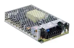
LAD-120D
AC/DC Enclosed Power Supply (PSU), ITE & Industrial, 2 Outputs, 121.99 W, 55.2 V, 1.21 A, 55.2 V
⚠️ Reference pricing provided. In case of supply shortages, we will connect you with our trusted procurement partners to ensure your project's continuity.
- Manufacturer: MEAN WELL
- Product type: AC / DC Enclosed Power Supplies
- SVHC: No SVHC (25-Jun-2025)
- Product Range: LAD-120 Series
- No. of Outputs: 2Outputs
- Output Power Max: 121.99W
- Input Voltage VAC: 90V AC to 264V AC
- Power Supply Output Type: Fixed
- Output Current - Output 1: 1.21A
- Output Current - Output 2: 1A
- Output Current - Output 3: -
- Output Current - Output 4: -
- Output Voltage - Output 1: 55.2V
- Output Voltage - Output 2: 55.2V
- Output Voltage - Output 3: -
- Output Voltage - Output 4: -
- Power Supply Applications: ITE & Industrial
| Delivery and price | |
|---|---|
| Units per pack | 100 |
| Price | 25.09 € |
| Current stock | 10+ |
| Lead time | 30 days |
Datasheet

**LAD-12 0 series** MEAN WELL 120W Economical Security/Fire Alarm PSU with Battery Charger/UPS **series** ~~eC~~ Adis & eK **UL62368-1 TPTC004** Hl **AS/NZS62368.1** & CBCE **IEC62368-1** & ## ■ **** ## ■ **** - ‧ - ‧ - ‧ - ‧ - - ‧ - - ‧ - ‧ - • - ‧ - ‧ - ‧ - - ‧℃ - ‧ - ‧ - ‧ ## ■ **** https://www.meanwell.com/serviceGTIN.aspx - ‧ - ‧ ## ■ **** ## ■ **** ## **** **** _File Name:LAD-120-SPEC 2024-01-26_ **LAD-12 0 series** 120W Economical Security/Fire Alarm PSU with Battery Charger/UPS ## **SPECIFICATION** |**MODEL**<br>**DC VOLTAGE**<br>**RATED CURRENT**<br>**CURRENT RANGE**<br>**RATED POWER**<br>**OUTPUT**<br>**VOLTAGE ADJ. RANGE**<br>**LINE REGULATION**<br>**LOAD REGULATION**<br>**SETUP, RISE TIME**<br>**HOLD UP TIME (Typ.)**<br>**VOLTAGE RANGE**<br>**FREQUENCY RANGE**<br>**EFFICIENCY (Typ.)**<br>**INPUT**<br>**INRUSH CURRENT (Typ.)**<br>**LEAKAGE CURRENT**<br>**SAFETY STANDARDS**<br>**WORKING TEMP.**<br>**WORKING HUMIDITY**<br>**STORAGE TEMP., HUMIDITY**<br>**TEMP. COEFFICIENT**<br>**VIBRATION**<br>**MTBF**<br>**DIMENSION**<br>**OTHERS**<br>**NOTE**<br>**PACKING**<br>**OVERLOAD**<br>**OVER VOLTAGE**<br>**BATTERY CUTOFF**<br>**AC CURRENT (Typ.)**<br>-20 ~ +60℃(Refer to "Derating Curve")<br>20 ~ 95% RH non-condensing<br>-30 ~ +85℃, 10 ~ 95% RH non-condensing<br>±0.03%/℃(0 ~ 50℃)<br>10 ~ 500Hz, 5G 10min./1cycle, 60min. each along X, Y, Z axes<br>**RIPPLE & NOISE (max.)Note.2**<br>**VOLTAGE TOLERANCENote.3**<br>**ENVIRONMENT**<br>**SAFETY &**<br>**EMC**<br>**(Note 4)**<br>**PROTECTION**<br>**WITHSTAND VOLTAGE**<br>**ISOLATION RESISTANCE**<br>I/P-O/P:3KVAC I/P-FG:2KVAC O/P-FG:0.5KVAC<br>I/P-O/P, I/P-FG, O/P-FG:100M Ohms / 500VDC / 25℃/ 70% RH<br>1. All parameters NOT specially mentioned are measured at 230VAC input, rated load and 25℃of ambient temperature.<br>2. Ripple & noise are measured at 20MHz of bandwidth by using a 12" twisted pair-wire terminated with a 0.1μF & 47μF parallel capacitor.<br>3. Tolerance : includes set up tolerance, line regulation and load regulation.<br>4. The power supply is considered a component which will be installed into a final equipment. All the EMC tests are been executed by mounting the unit on<br> 360mm*360mm metal plate with 1mm of thickness. The final equipment must be re-confirmed that it still meets EMC directives. For guidance on how to<br>perform these EMC tests, please refer to “EMI testing of component power supplies.”<br>(as available on https://www.meanwell.com//Upload/PDF/EMI_statement_en.pdf )<br>5. Test harmonic current at 85% load.<br>6. The ambient temperature derating of 3.5℃/1000m with fanless models and of 5℃/1000m with fan models for operating altitude higher than 2000m(6500ft).<br>※Product Liability Disclaimer:For detailed information, please refer to https://www.meanwell.com/serviceDisclaimer.aspx<br>**OUTPUT NUMBER**<br>**EMC IMMUNITY**<br>**EMC EMISSION**<br>**Parameter**<br>**Parameter**<br>ESD<br>Radiated<br>EFT / Burst<br>Surge<br>Conducted<br>Magnetic Field<br>Conducted<br>Radiated<br>Voltage Flicker<br>**Standard**<br>**Standard**<br>BS EN/EN55032 (CISPR32),<br>EAC TP TC 020<br>BS EN/EN55032 (CISPR32),<br>EAC TP TC 020<br>BS EN/EN61000-4-2<br>BS EN/EN61000-4-3<br>BS EN/EN61000-4-4<br>BS EN/EN61000-4-5<br>BS EN/EN61000-4-6<br>BS EN/EN61000-4-8<br>**Test Level / Note**<br>**Test Level / Note**<br>Level 3, 8KV air ; Level 2, 6KV contact; criteria A<br>Level 3, 10V/m ; criteria A<br>Level 3, 2KV ; criteria A<br>Level 3, 1KV/Line-Line ;2KV/Line-FG ;criteria A<br>Level 3, 10V ; criteria A<br>Level 4, 30A/m ; criteria A<br>Class A<br>Class A<br>-----<br>-----<br>CH1:105 ~ 135% CH2:90 ~ 110%<br>9.5V±0.5V<br>32V±0.5V<br>CH1:15.5 ~ 18V<br>CH1:47 ~ 55V<br>**LAD-120A**<br>**LAD-120C**<br>43V±0.5V<br>CH1:61 ~ 71V<br>**LAD-120D**<br>21.5V±0.5V<br>CH1:31 ~ 36V<br>**LAD-120B**<br>**BATTERY STATIC DISCHARGE**<br>**CURRENT**<br><100μA<br>**OVER TEMPERATURE**<br>**DISCHARGE**<br>**FUNCTION**<br>TTL signal, High / Open :<br>; Low :<br>charge ; Ice : max. 30mA@ 50VDC<br>Charge<br>Dis<br>**BATTERY FULL**<br>**AC OK**<br>TTL signal, High / Open : AC Fail ; Low : AC OK ; Ice : max. 30mA@ 50VDC<br>TTL signal, High / Open : Battery charging ; Low : Battery full ; Ice : max. 30mA@ 50VDC<br>**BATTERY DISCONNECT/**<br>**REVERSE POLARITY**<br>**BATTERY LOW**<br>TTL signal, High / Open : Battery connect/normal ; Low : Battery disconnect/reverse polarity; Ice : max. 30mA@ 50VDC<br>TTL signal, High / Open : Battery normal ; Low : Battery low; Ice : max. 30mA@ 50VDC<br>Protection type : Shut down o/p voltage, re-power on to removed<br>Protection type : Shut down o/p voltage, re-power on to removed<br>Protection type : CH1 OLP, CH2 with battery: The unit will enter to UPS mode when CH1 is around 105%~160%,<br>when total output of CH1 + CH2 reach around 125%~135% output hiccup(120D shuts down)<br>CH1 OLP, CH2 without battery:Hiccup mode o/p voltage, recovers automatically after fault condition is removed<br>(120D shuts down,re-power on to removed)<br>CH2 :<br>fault condition<br>Constant current limiting;<br>does not affect CH1 working,recovers automatically after fault<br>condition is removed (External fuse is mandatory in series connection with battery for protection)<br>**BATTERY REVERSE POLARITY**Protected when reverse polarity ,<br>, recovers automatically after fault condition is removed<br>no damage<br>UL62368-1,<br>approved;<br>BS EN/EN62368-1, AS/NZS62368.1,EAC TP TC 004<br>Design refer to GB 17945-2010<br>500ms, 40ms/230VAC 500ms, 40ms/115VAC at full load<br>40ms/230VAC 9ms/115VAC at full load<br>27.6V<br>CH2<br>41.5V<br>CH2<br>13.8V<br>CH1<br>41.5V<br>CH1<br>0 ~ 8.7A<br>0 ~ 2.9A<br>--------<br>--------<br>120mVp-p<br>240mVp-p<br>CH1: 10.8 ~ 14.5V<br>CH1: 32.4 ~ 43.5V<br>--------<br>--------<br>--------<br>--------<br>--------<br>--------<br>±1.0%<br>±1.0%<br>±0.5%<br>±0.5%<br>±0.5%<br>±0.5%<br>55.2V<br>CH2<br>55.2V<br>CH1<br>0 ~ 2.21A<br>--------<br>360mVp-p<br>Ch1: 43.5 ~ 58V<br>--------<br>--------<br>--------<br>±1.0%<br>±0.5%<br>±0.5%<br>27.6V<br>CH1<br>0 ~ 4.4A<br>150mVp-p<br>CH1: 21.6 ~ 29V<br>±1.0%<br>±0.5%<br>±0.5%<br>13.8V<br>CH2<br>--------<br>--------<br>--------<br>--------<br>7.7A<br>1.9A<br>1.21A<br>3.4A<br>1A(Battery Charger)<br>120W<br>120.35W<br>121.99W<br>121.4W<br>47 ~ 63Hz<br>2.5A/115VAC 1.5A/230VAC<br>COLD START 30A/115VAC 55A/230VAC<br>0.5mA / 240VAC<br>90 ~ 264VAC 127 ~ 370VDC<br>86%<br>88%<br>88%<br>88%<br>Harmonic Current<br>(Note 5)<br>Class A<br>BS EN/EN61000-3-2<br>159*97*30mm (L*W*H)<br>0.42Kg; 30pcs/13.6Kg/0.77CUFT<br>1509.9K hrs min. Telcordia SR-332 (Bellcore); 209.4K hrs min. MIL-HDBK-217F (25℃)<br>--------<br>--------<br>--------<br>--------<br>1A(Battery Charger)<br>1A(Battery Charger)<br>1A(Battery Charger)|**MODEL**<br>**DC VOLTAGE**<br>**RATED CURRENT**<br>**CURRENT RANGE**<br>**RATED POWER**<br>**OUTPUT**<br>**VOLTAGE ADJ. RANGE**<br>**LINE REGULATION**<br>**LOAD REGULATION**<br>**SETUP, RISE TIME**<br>**HOLD UP TIME (Typ.)**<br>**VOLTAGE RANGE**<br>**FREQUENCY RANGE**<br>**EFFICIENCY (Typ.)**<br>**INPUT**<br>**INRUSH CURRENT (Typ.)**<br>**LEAKAGE CURRENT**<br>**SAFETY STANDARDS**<br>**WORKING TEMP.**<br>**WORKING HUMIDITY**<br>**STORAGE TEMP., HUMIDITY**<br>**TEMP. COEFFICIENT**<br>**VIBRATION**<br>**MTBF**<br>**DIMENSION**<br>**OTHERS**<br>**PACKING**<br>**OVERLOAD**<br>**OVER VOLTAGE**<br>**BATTERY CUTOFF**<br>**AC CURRENT (Typ.)**<br>**RIPPLE & NOISE (max.)Note.2**<br>**VOLTAGE TOLERANCENote.3**<br>**ENVIRONMENT**<br>**SAFETY &**<br>**EMC**<br>**(Note 4)**<br>**PROTECTION**<br>**WITHSTAND VOLTAGE**<br>**ISOLATION RESISTANCE**<br>**OUTPUT NUMBER**<br>**EMC IMMUNITY**<br>**EMC EMISSION**<br>**BATTERY STATIC DISCHARGE**<br>**CURRENT**<br>**OVER TEMPERATURE**<br>**DISCHARGE**<br>**FUNCTION**<br>**BATTERY FULL**<br>**AC OK**<br>**BATTERY DISCONNECT/**<br>**REVERSE POLARITY**<br>**BATTERY LOW**<br>**BATTERY REVERSE POLARITY**|**MODEL**<br>**DC VOLTAGE**<br>**RATED CURRENT**<br>**CURRENT RANGE**<br>**RATED POWER**<br>**OUTPUT**<br>**VOLTAGE ADJ. RANGE**<br>**LINE REGULATION**<br>**LOAD REGULATION**<br>**SETUP, RISE TIME**<br>**HOLD UP TIME (Typ.)**<br>**VOLTAGE RANGE**<br>**FREQUENCY RANGE**<br>**EFFICIENCY (Typ.)**<br>**INPUT**<br>**INRUSH CURRENT (Typ.)**<br>**LEAKAGE CURRENT**<br>**SAFETY STANDARDS**<br>**WORKING TEMP.**<br>**WORKING HUMIDITY**<br>**STORAGE TEMP., HUMIDITY**<br>**TEMP. COEFFICIENT**<br>**VIBRATION**<br>**MTBF**<br>**DIMENSION**<br>**OTHERS**<br>**PACKING**<br>**OVERLOAD**<br>**OVER VOLTAGE**<br>**BATTERY CUTOFF**<br>**AC CURRENT (Typ.)**<br>**RIPPLE & NOISE (max.)Note.2**<br>**VOLTAGE TOLERANCENote.3**<br>**ENVIRONMENT**<br>**SAFETY &**<br>**EMC**<br>**(Note 4)**<br>**PROTECTION**<br>**WITHSTAND VOLTAGE**<br>**ISOLATION RESISTANCE**<br>**OUTPUT NUMBER**<br>**EMC IMMUNITY**<br>**EMC EMISSION**<br>**BATTERY STATIC DISCHARGE**<br>**CURRENT**<br>**OVER TEMPERATURE**<br>**DISCHARGE**<br>**FUNCTION**<br>**BATTERY FULL**<br>**AC OK**<br>**BATTERY DISCONNECT/**<br>**REVERSE POLARITY**<br>**BATTERY LOW**<br>**BATTERY REVERSE POLARITY**|**LAD-120A**<br>**LAD-120C**<br>**LAD-120D**<br>**LAD-120B**|**LAD-120A**<br>**LAD-120C**<br>**LAD-120D**<br>**LAD-120B**|**LAD-120A**<br>**LAD-120C**<br>**LAD-120D**<br>**LAD-120B**|**LAD-120A**<br>**LAD-120C**<br>**LAD-120D**<br>**LAD-120B**|**LAD-120A**<br>**LAD-120C**<br>**LAD-120D**<br>**LAD-120B**|**LAD-120A**<br>**LAD-120C**<br>**LAD-120D**<br>**LAD-120B**|**LAD-120A**<br>**LAD-120C**<br>**LAD-120D**<br>**LAD-120B**|**LAD-120A**<br>**LAD-120C**<br>**LAD-120D**<br>**LAD-120B**|**LAD-120A**<br>**LAD-120C**<br>**LAD-120D**<br>**LAD-120B**| |---|---|---|---|---|---|---|---|---|---|---|---| |||**OUTPUT NUMBER**|CH1|CH2|CH1||CH2|CH1|CH2|CH1|CH2| |||**DC VOLTAGE**|13.8V|13.8V|27.6V||27.6V|41.5V|41.5V|55.2V|55.2V| |||**RATED CURRENT**|7.7A|1A(Battery Charger)|3.4A||1A(Battery Charger)|1.9A|1A(Battery Charger)|1.21A|1A(Battery Charger)| |||**CURRENT RANGE**|0 ~ 8.7A|--------|0 ~ 4.4A||--------|0 ~ 2.9A|--------|0 ~ 2.21A|--------| |||**RATED POWER**|120W||121.4W|||120.35W||121.99W|| |||**RIPPLE & NOISE (max.)Note.2**|120mVp-p|--------|150mVp-p||--------|240mVp-p|--------|360mVp-p|--------| |||**VOLTAGE ADJ. RANGE**|CH1: 10.8 ~ 14.5V||CH1: 21.6 ~ 29V|||CH1: 32.4 ~ 43.5V||Ch1: 43.5 ~ 58V|| |||**VOLTAGE TOLERANCENote.3**|±1.0%|--------|±1.0%||--------|±1.0%|--------|±1.0%|--------| |||**LINE REGULATION**|±0.5%|--------|±0.5%||--------|±0.5%|--------|±0.5%|--------| |||**LOAD REGULATION**|±0.5%|--------|±0.5%||--------|±0.5%|--------|±0.5%|--------| |||**SETUP, RISE TIME**|500ms, 40ms/230VAC 500ms, 40ms/115VAC at full load||||||||| |||**HOLD UP TIME (Typ.)**|40ms/230VAC 9ms/115VAC at full load||||||||| |||**BATTERY STATIC DISCHARGE**<br>**CURRENT**|<100μA||||||||| |||**VOLTAGE RANGE**|90 ~ 264VAC 127 ~ 370VDC||||||||| |||**FREQUENCY RANGE**|47 ~ 63Hz||||||||| |||**EFFICIENCY (Typ.)**|86%||88%|||88%||88%|| |||**AC CURRENT (Typ.)**|2.5A/115VAC 1.5A/230VAC||||||||| |||**INRUSH CURRENT (Typ.)**|COLD START 30A/115VAC 55A/230VAC||||||||| |||**LEAKAGE CURRENT**|0.5mA / 240VAC||||||||| |||**OVERLOAD**|CH1:105 ~ 135% CH2:90 ~ 110%<br>Protection type : CH1 OLP, CH2 with battery: The unit will enter to UPS mode when CH1 is around 105%~160%,<br>when total output of CH1 + CH2 reach around 125%~135% output hiccup(120D shuts down)<br>CH1 OLP, CH2 without battery:Hiccup mode o/p voltage, recovers automatically after fault condition is removed<br>(120D shuts down,re-power on to removed)<br>CH2 :<br>fault condition<br>Constant current limiting;<br>does not affect CH1 working,recovers automatically after fault<br>condition is removed (External fuse is mandatory in series connection with battery for protection)||||||||| |||**OVER VOLTAGE**|CH1:15.5 ~ 18V<br>CH1:47 ~ 55V<br>CH1:61 ~ 71V<br>CH1:31 ~ 36V<br>Protection type : Shut down o/p voltage, re-power on to removed||||||||| |||**OVER TEMPERATURE**|Protection type : Shut down o/p voltage, re-power on to removed||||||||| |||**BATTERY REVERSE POLARITY**|Protected when reverse polarity ,<br>, recovers automatically after fault condition is removed<br>no damage||||||||| |||**BATTERY CUTOFF**|9.5V±0.5V||21.5V±0.5V|||32V±0.5V||43V±0.5V|| |||**AC OK**|TTL signal, High / Open : AC Fail ; Low : AC OK ; Ice : max. 30mA@ 50VDC||||||||| |||**BATTERY DISCONNECT/**<br>**REVERSE POLARITY**|TTL signal, High / Open : Battery connect/normal ; Low : Battery disconnect/reverse polarity; Ice : max. 30mA@ 50VDC||||||||| |||**BATTERY LOW**|TTL signal, High / Open : Battery normal ; Low : Battery low; Ice : max. 30mA@ 50VDC||||||||| |||**BATTERY FULL**|TTL signal, High / Open : Battery charging ; Low : Battery full ; Ice : max. 30mA@ 50VDC||||||||| |||**DISCHARGE**|TTL signal, High / Open :<br>; Low :<br>charge ; Ice : max. 30mA@ 50VDC<br>Charge<br>Dis||||||||| |||**WORKING TEMP.**|-20 ~ +60℃(Refer to "Derating Curve")||||||||| |||**WORKING HUMIDITY**|20 ~ 95% RH non-condensing||||||||| |||**STORAGE TEMP., HUMIDITY**|-30 ~ +85℃, 10 ~ 95% RH non-condensing||||||||| |||**TEMP. COEFFICIENT**|±0.03%/℃(0 ~ 50℃)||||||||| |||**VIBRATION**|10 ~ 500Hz, 5G 10min./1cycle, 60min. each along X, Y, Z axes||||||||| |||**SAFETY STANDARDS**|UL62368-1,<br>approved;<br>BS EN/EN62368-1, AS/NZS62368.1,EAC TP TC 004<br>Design refer to GB 17945-2010||||||||| |||**WITHSTAND VOLTAGE**|I/P-O/P:3KVAC I/P-FG:2KVAC O/P-FG:0.5KVAC||||||||| |||**ISOLATION RESISTANCE**|I/P-O/P, I/P-FG, O/P-FG:100M Ohms / 500VDC / 25℃/ 70% RH||||||||| |||**MTBF**<br>**EMC IMMUNITY**<br>**EMC EMISSION**|**Parameter**|||**Standard**|||**Test Level / Note**||| ||||Conducted|||BS EN/EN55032 (CISPR32),<br>EAC TP TC 020|||Class A||| ||||Radiated|||BS EN/EN55032 (CISPR32),<br>EAC TP TC 020|||Class A||| ||||Harmonic Current<br>(Note 5)|||BS EN/EN61000-3-2|||Class A||| ||||Voltage Flicker|||-----|||-----||| ||||**Parameter**|||**Standard**|||**Test Level / Note**||| ||||ESD|||BS EN/EN61000-4-2|||Level 3, 8KV air ; Level 2, 6KV contact; criteria A||| ||||Radiated|||BS EN/EN61000-4-3|||Level 3, 10V/m ; criteria A||| ||||EFT / Burst|||BS EN/EN61000-4-4|||Level 3, 2KV ; criteria A||| ||||Surge|||BS EN/EN61000-4-5|||Level 3, 1KV/Line-Line ;2KV/Line-FG ;criteria A||| ||||Conducted|||BS EN/EN61000-4-6|||Level 3, 10V ; criteria A||| ||||Magnetic Field|||BS EN/EN61000-4-8|||Level 4, 30A/m ; criteria A||| ||||1509.9K hrs min. Telcordia SR-332 (Bellcore); 209.4K hrs min. MIL-HDBK-217F (25℃)||||||||| |||**DIMENSION**|159*97*30mm (L*W*H)<br>||||||||| |||**PACKING**|0.42Kg; 30pcs/13.6Kg/0.77CUFT||||||||| |||1. All parameters NOT specially mentioned are measured at 230VAC input, rated load and 25℃of ambient temperature.<br>2. Ripple & noise are measured at 20MHz of bandwidth by using a 12" twisted pair-wire terminated with a 0.1μF & 47μF parallel capacitor.<br>3. Tolerance : includes set up tolerance, line regulation and load regulation.<br>4. The power supply is considered a component which will be installed into a final equipment. All the EMC tests are been executed by mounting the unit on<br> 360mm*360mm metal plate with 1mm of thickness. The final equipment must be re-confirmed that it still meets EMC directives. For guidance on how to<br>perform these EMC tests, please refer to “EMI testing of component power supplies.”<br>(as available on https://www.meanwell.com//Upload/PDF/EMI_statement_en.pdf )<br>5. Test harmonic current at 85% load.<br>6. The ambient temperature derating of 3.5℃/1000m with fanless models and of 5℃/1000m with fan models for operating altitude higher than 2000m(6500ft).<br>※Product Liability Disclaimer:For detailed information, please refer to https://www.meanwell.com/serviceDisclaimer.aspx|||||||||| 1. All parameters NOT specially mentioned are measured at 230VAC input, rated load and 25℃ of ambient temperature. 2. Ripple & noise are measured at 20MHz of bandwidth by using a 12" twisted pair-wire terminated with a 0.1μF & 47μF parallel capacitor. 3. Tolerance : includes set up tolerance, line regulation and load regulation. 4. The power supply is considered a component which will be installed into a final equipment. All the EMC tests are been executed by mounting the unit on - **NOTE** 360mm*360mm metal plate with 1mm of thickness. The final equipment must be re-confirmed that it still meets EMC directives. For guidance on how to perform these EMC tests, please refer to “EMI testing of component power supplies.” (as available on https://www.meanwell.com//Upload/PDF/EMI_statement_en.pdf ) 5. Test harmonic current at 85% load. 6. The ambient temperature derating of 3.5℃/1000m with fanless models and of 5℃/1000m with fan models for operating altitude higher than 2000m(6500ft). ※ Product Liability Disclaimer:For detailed information, please refer to https://www.meanwell.com/serviceDisclaimer.aspx _File Name:LAD-120-SPEC 2024-01-26_ **LAD-12 0 series** ## 120W Economical Security/Fire Alarm PSU with Battery Charger/UPS **==> picture [511 x 668] intentionally omitted <==** **----- Start of picture text -----**<br> Block Diagram<br>fosc : 65KHz<br>BAT+<br>BAT. CHARGER<br>BAT-<br>RELAY<br>S.W<br>UPS<br>FUNCTION<br>EMI FILTER POWER RECTIFIERS +V<br>I/P & &<br>AC RECTIFIERS SWITCHING FILTER -V<br>ON/OFF<br>S.W<br>O.L.P.<br>FG<br>DETECTION<br>ACTIVE CIRCUIT<br>PWM <br>START<br>CONTROL Battery disconnect/<br>CIRCUIT polarity reverse<br>O.V.P. TTL Signal<br>Battery low<br>Battery full<br>Discharge<br>Derating Curve<br>100<br>80<br>60<br>40<br>20<br>-20 -10 0 10 20 30 40 50 60 (HORIZONTAL)<br>AMBIENT TEMPERATURE ( ℃ )<br>Static Characteristics<br>100<br>90<br>80<br>70<br>90 100 110 115 120 140 160 180 200 220 240 264<br>INPUT VOLTAGE (VAC) 60Hz<br>LOAD (%)<br>LOAD (%)<br>**----- End of picture text -----**<br> _File Name:LAD-120-SPEC 2024-01-26_ **LAD-12 0 series** 120W Economical Security/Fire Alarm PSU with Battery Charger/UPS ## **Suggested Application** ## **1.DC-UPS function** When AC voltage is abnormal,The UPS function will activate and power source switch battery backup. **==> picture [473 x 604] intentionally omitted <==** **----- Start of picture text -----**<br> AC mains Input<br>TTL<br>▪ <br>~<br>▪ <br>▪ <br>▪ <br>▪ <br>Force start UPS mode Charging<br>CN2<br>Battery Load<br>PIN7,8<br>2.Function signals by TTL<br> TTL Signal is sent out through pins from CN2.<br> External voltage source is required for the TTL signal. The maximum voltage is 50VDC and the maximum sink current is 30mA.<br>R<br>V<br>| |<br>a<br>External voltage and resistor<br>(The max. sink current is 30mA at 50VDC)<br>2.1 AC OK : Detection of AC status<br>Between pin 1 and pin 4 Description<br>Low<br>The signal is "Low" when the AC input is normal<br>(0.3V max. at 30mA)<br>High or open<br>The signal turns to be "High" when the AC input is abnormal<br>(External applied voltage 50V max.)<br>2 1<br>4<br>R<br>8 7<br>V<br>= z<br>2.2 Battery Disconnected/Reverse Polarity: Battery status detection<br>Between pin 2 and pin 4 Description<br>Low<br>The signal is "Low" when the battery is not connected or inversely connected<br>(0.3V max. at 30mA)<br>High or open<br>The signal turns to be "High" when the battery is connected or normal<br>(External applied voltage 50V max.)<br>Note. The signals of battery disconnected and reverse polarity can only be detected during the first power transmission ,<br> it is can not be detected at any time.<br>**----- End of picture text -----**<br> ## **2.Function signals by TTL** _File Name:LAD-120-SPEC 2024-01-26_ **LAD-12 0 series** 120W Economical Security/Fire Alarm PSU with Battery Charger/UPS **==> picture [349 x 646] intentionally omitted <==** **----- Start of picture text -----**<br> 2 1<br>4<br>R<br>| | 8 7<br>V<br>2.3 Battery Low: Battery low detection<br>Between pin 3 and pin 4 Description<br>Low<br>The signal is "Low" when the battery is under voltage protected<br>(0.3V max. at 30mA)<br>High or open<br>The signal turns to be "High" when the battery is normal<br>(External applied voltage 50V max.)<br>2 1<br>4 3<br>R<br>8 7<br>V<br>2.4 Battery Full : Battery full detection<br>Between pin 4 and pin 5 Description<br>Low<br>The signal is "Low" when the battery is fully charged<br>(0.3V max. at 30mA)<br>High or open<br>The signal turns to be "High" when the battery is charged<br>(External applied voltage 50V max.)<br>2 1<br>4<br>5<br>- - —- es oe 8 afaatl 7 R<br>V<br>2.5 Discharge: Discharge detection<br>Between pin 4 and pin 6 Description<br>Low<br>The signal is "Low" when the power supply is discharging<br>(0.3V max. at 30mA)<br>High or open<br>The signal is "High" when the main power is working<br>(External applied voltage 50V max.)<br>2 1<br>4<br>V 6<br>8 7<br>R<br>2.6 Forced Start: Forced start UPS mode<br>Pin 7 & 8 Status<br>Short Forced start UPS mode<br>Open Normal<br>2 1<br>8 7<br>4 : ae deat boat inal iol ioral le <a | =<br>**----- End of picture text -----**<br> _File Name:LAD-120-SPEC 2024-01-26_ **LAD-12 0 series** ## W m 120W Economical Security/Fire Alarm PSU with Battery Charger/UPS ## **Mechanical Specification** Case No. Unit:mm **==> picture [436 x 463] intentionally omitted <==** **----- Start of picture text -----**<br> 159<br>4.5<br>| | r<br>AC ON/OFF S.W<br>_ —_ 1 = TB1 ScHiss<br>ETi 2 ro l HEI<br>Ni HS 3 ro Baeeeeoe<br>£<br>4 =<br>5<br>e e<br>6<br>— e<br>7 pal<br>BAT. connected/<br>Disconnected S.W ae<br>FL. Bills E L<br>CN2 |<br>j eBeesHEREsn e esetEEEoe E ——<br>= ae Iz:<br>!ora<br>Air flow<br>direction<br>6.5 150<br>yo]<br>rt ;<br>|<br>Ot<br>=| 22 117<br>Connector Pin No. Assignment(CN2) ※ Terminal Pin No. Assignment(TB1)<br>Pin No. Assignment(TTL Signal) Mating Housing Terminal Pin No. Assignment<br>1 AC OK 1 AC/L<br>Battery disconnect/ 2 AC/N<br>2<br>reverse polarity 3 FG<br>3 Battery low TKP DH2 TKP DHT-1S(LF) — 4 DC OUTPUT -V<br>4 GND or equivalent or equivalent == 5 DC OUTPUT +V<br>5 Battery full 6 BAT -<br>6 Discharge oO 7 BAT +<br>Open : normal<br>7,8<br>Short : forced start UPS mode A<br>DC OUTPUT -V and BAT - can not be shorted.<br>3-M3 L=5<br>φ3.5<br>φ3.5<br>5.5<br>97<br>3.5<br>6.5<br>26 18 30<br>15 6 3.5 14.5<br>**----- End of picture text -----**<br> ※ Connector Pin No. Assignment(CN2) ## **Installation Manual** Please refer to : http://www.meanwell.com/manual.html _File Name:LAD-120-SPEC 2024-01-26_
Updated at June 6, 2026
About Novapart
Novapart is a B2B electronic component broker specialising in stock shortages and cost reduction. We source hard-to-find parts and identify compliant alternatives across a catalogue of 410,000+ components from 500+ manufacturers.
Learn more →Stock Shortage Specialist
When a component is unavailable, discontinued or has an unacceptable lead time, we tap into our network of vetted European and Asian distributors to source what you need — without compromising on quality or traceability.
Request a quote →Compliant Alternatives
We identify pin-to-pin, electrically equivalent substitutes that meet the same certifications (RoHS, AEC-Q100, REACH) as your original specification — validated against datasheets, not just part numbers. Often at a lower cost.
BOM Analysis service →