

L001266-01
RF Antenna, 4.4GHz to 5.925GHz, -4.6dBi, 1.6 VSWR, Stud Mount / SMA Connector
- Manufacturer: TE CONNECTIVITY
- Product type:
- Gain: -4.6dBi
- SVHC: Lead (04-Feb-2026)
- VSWR: 1.6
- Input Power: -
- Antenna Type: 2G / 3G / 4G / 5G / CBRS / Cellular / Dome / IoT / ISM / LTE / Puck / TN / NTN
- Frequency Max: 5.925GHz
- Frequency Min: 4.4GHz
- Product Range: -
- Input Impedance: -
- Antenna Mounting: Stud Mount / SMA Connector
- Antenna Polarisation: -
| Delivery and price | |
|---|---|
| Units per pack | 100 |
| Price | 27.59 € |
| Current stock | 200+ |
| Lead time | 30 days |
## TN & NTN Dual-Mode Antenna - Satellite IoT Direct to Device Ready
> [Direct Mount 5G/LTE Antenna ] Covering 4G/5G/Satellite Band 25
## **Satellite IoT D2D Ready**
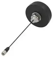
The L001266-01 direct to device (D2D) antenna offers 4G/5G/ satellite band 25 cellular coverage through an external panel mount puck-style multiband antenna.
L001266-01 provides a ground plane independent antenna solution which mounts permanently to metallic and non-metallic surfaces. The antenna terminates in an SMA plug (male pin) connector on RG-174/U coaxial cable enabling an environmentally sealed enclosure and protection from tampering.
## SATELLITE IOT D2D COMMUNICATIONS
Low Earth Orbit (LEO) satellites, positioned a few hundred km’s above Earth, orbit rapidly and are ideal for IoT networks. A LEO satellite constellation can now support low data rate communications through specific LTE frequencies.
- Dual-mode capable - Supporting Terrestrial Networks (TN) and Non-Terrestrial Networks (NTN) from a single antenna
- 410-5925 MHz terrestrial cellular coverage
- Band 25 (1900 MHz) cellular satellite coverage
- Testing available for other/future cellular satellite D2D frequency bands used by various network providers
- Enabling dual-mode communications via IoT devices
- Prioritizing terrestrial networks but capable of automatically switching to satellite when the signal is weak or unavailable
## REFERENCE SIGNAL RECEIVED POWER (RSRP) VALUES
The L001266-01 antenna was live-tested for receive signal strength. Data encompasses multiple satellite pass-overs, showing signal strength variation; exceeding the -120 dBm minimum for IoT devices.
**==> picture [276 x 153] intentionally omitted <==**
**----- Start of picture text -----**<br>
-100<br>-102<br>-104<br>-106<br>-108<br>-110<br>-112<br>-114<br>-116<br>-118<br>-120<br>1 2 3 4 5 6 7 8 9 10<br>Data Point<br>RSRP (dBm)<br>**----- End of picture text -----**<br>
An RSRP value of -120 dBm is generally the recognized minimum requirement suitable for the data rates of SMS, CAT-1, CAT-1 Bis connectivity.
RSRP can be susceptible to fluctuations for a variety of reasons. These can include: satellite elevation angle: antenna radiation patterns; solar flares; atmospheric conditions, and more.
DIGITAL DATA NETWORKS / L001266-01 DIRECT TO DEVICE DUAL-MODE SATELLITE IOT ANTENNA
## **FEATURES**
- Validated for use on satcom D2D networks
- Dual-Mode TN and NTN capable
- Wide Bandwidth: 617 MHz to 960 MHz
- Performance at 617 MHz to 5925 MHz
- Peak Gain: 5.4 dBi
- Performance at 3300 MHz to 4200 MHz
- Peak Gain: 2.7 dBi
- Ground plane independent dipole antenna
- External mount, includes all hardware for installation including M12x1 hex nut, washer and optional boot
## **APPLICATIONS**
- Non-Terrestrial and Terrestrial Networks
- Satellite IoT D2D (Direct to Device) applications
- Worldwide 5G/4G/3G/2G
- Cellular IoT: LTE-M (Cat-M1) and NB-IoT
- 410 MHz LTE
- 4.9 GHz Public Safety
- Remote control, monitoring and sensing
- Internet of Things (IoT) devices
- SMA plug (male pin) gold plated connection
- IP65/IP67 rated
## **ORDERING INFORMATION**
**==> picture [528 x 85] intentionally omitted <==**
**----- Start of picture text -----**<br>
Part Number Description<br>1 meter (39.37 in) 5G/LTE panel mount antenna with SMA plug (male pin) on RG-174/U coaxial cable<br>L001266-01<br>and mounting hardware, including M12x1 hex nut, washer and rubber boot<br>**----- End of picture text -----**<br>
## **TABLE 1. ELECTRICAL SPECIFICATIONS**
**==> picture [528 x 162] intentionally omitted <==**
**----- Start of picture text -----**<br>
Bands Frequency Range VSWR Peak Gain Avg. Gain Efficiency<br>(max.) (dBi) (dBi) (%)<br>87, 88 410 MHz to 426 MHz 1.8 -0.1 -5.1 33<br>72, 73 450 MHz to 470 MHz 2.9 -4.2 -12.8 8<br>5, 8, 12, 13, 14, 17, 18, 19, 20,<br>26, 27, 28, 29, 44, 67, 69, 81, 617 MHz to 960 MHz 3.0 5.4 -6.9 27<br>82, 83, 89<br>1, 2, 3, 4, 9, 10, 25, 33, 34,<br>35, 36, 37, 39, 65, 66, 80, 84, 1695 MHz to 2200 MHz 2.2 3.8 -10.4 26<br>86, 95<br>30, 40 2300 MHz to 2400 MHz 1.3 4.2 -3.1 52<br>7, 41 2496 MHz to 2690 MHz 1.6 2.7 -5.2 33<br>22, 42, 43, 48, 49, 52, n77,<br>3300 MHz to 4200 MHz 1.6 2.7 -5.7 32<br>n78<br>n79 4400 MHz to 5925 MHz 1.6 5.1 -4.6 39<br>**----- End of picture text -----**<br>
Electrical specifications and plots measured with the antenna in a free space orientation.
Electrical specifications and plots measured with a 300 mm x 300 mm (11.8 in x 11.8 in) ground plane.
DIGITAL DATA NETWORKS / L001266-01 DIRECT TO DEVICE DUAL-MODE SATELLITE IOT ANTENNA
9
## **TABLE 2. MECHANICAL SPECIFICATIONS**
|Parameter|Value|
|---|---|
|Operating Temperature Range|-40 °C to +70 °C|
|Weight|63.4 g (2.24 oz)|
|Dimensions|23.3 mm x Ø54.7 mm (0.92 in x Ø2.15 in)|
|Connection|SMA Plug (male pin)|
|Cable|1 meter (39.37 in), 2 meters (78.74 in)|
|IP Rating|IP65/IP67 Ratable|
|Fire rating|UL94 HB|
## **PACKAGING INFORMATION**
The L001266-01 antenna is individually sealed in a clear plastic bag. Plastic bags are sealed in a larger plastic bag in quantities of 50 pcs. Distribution channels may offer alternative packaging options.
## **PRODUCT DIMENSIONS**
**==> picture [99 x 6] intentionally omitted <==**
**----- Start of picture text -----**<br>
Figure 1. L001266-01 Dimensions<br>**----- End of picture text -----**<br>
DIGITAL DATA NETWORKS / L001266-01 DIRECT TO DEVICE DUAL-MODE SATELLITE IOT ANTENNA
2
## **VSWR**
Figure 2 provides the voltage standing wave ratio (VSWR) across the antenna bandwidth. VSWR describes the power reflected from the antenna back to the radio. A lower VSWR value indicates better antenna performance at a given frequency. Reflected power is also shown on the right-side vertical axis as a gauge of the percentage of transmitter power reflected back from the antenna.
**==> picture [463 x 534] intentionally omitted <==**
**----- Start of picture text -----**<br>
5<br>40<br>4<br>30<br>3<br>20<br>2<br>10<br>1 0<br>400 800 1200 1600 2000 2400 2800 3200 3600 4000 4400 4800 5200 5600 6000<br>Frequency (MHz)<br>Figure 2. L001266-01 VSWR<br>Return loss (Figure 3), represents the loss in power at the antenna due to reflected signals. Like VSWR, a lower return loss value<br>indicates better antenna performance at a given frequency.<br>0<br>-5<br>-10<br>-15<br>-20<br>-25<br>400 800 1200 1600 2000 2400 2800 3200 3600 4000 4400 4800 5200 5600 6000<br>Frequency (MHz)<br>410 470 617 960 1695 2200230024002496 2690 3300 4200 4400 5925<br>VSWR<br>Reflected Power (%)<br>410 470 617 960 1695 2200230024002496 2690 3300 4200 4400 5925<br>Return Loss (dB)<br>**----- End of picture text -----**<br>
## **RETURN LOSS**
Return loss (Figure 3), represents the loss in power at the antenna due to reflected signals. Like VSWR, a lower return loss value indicates better antenna performance at a given frequency.
Figure 3. L001266-01 Return Loss
DIGITAL DATA NETWORKS / L001266-01 DIRECT TO DEVICE DUAL-MODE SATELLITE IOT ANTENNA
3
## **PEAK GAIN**
The peak gain across the antenna bandwidth is shown in Figure 4. Peak gain represents the maximum antenna input power concentration across 3-dimensional space, and therefore peak performance at a given frequency, but does not consider any directionality in the gain pattern.
**==> picture [461 x 230] intentionally omitted <==**
**----- Start of picture text -----**<br>
10<br>5<br>0<br>-5<br>-10<br>-15<br>-20<br>400 800 1200 1600 2000 2400 2800 3200 3600 4000 4400 4800 5200 5600 6000<br>Frequency (MHz)<br>410 470 617 960 1695 2200230024002496 2690 3300 4200 4400 5925<br>Peak Gain (dBi)<br>**----- End of picture text -----**<br>
Figure 4. L001266-01 Peak Gain
## **AVERAGE GAIN**
Average gain (Figure 5), is the average of all antenna gain in 3-dimensional space at each frequency, providing an indication of overall performance without expressing antenna directionality.
**==> picture [461 x 230] intentionally omitted <==**
**----- Start of picture text -----**<br>
10<br>5<br>0<br>-5<br>-10<br>-15<br>-20<br>400 800 1200 1600 2000 2400 2800 3200 3600 4000 4400 4800 5200 5600 6000<br>Frequency (MHz)<br>410 470 617 960 1695 2200230024002496 2690 3300 4200 4400 5925<br>Average Gain (dBi)<br>**----- End of picture text -----**<br>
Figure 5. L001266-01 Antenna Average Gain
DIGITAL DATA NETWORKS / L001266-01 DIRECT TO DEVICE DUAL-MODE SATELLITE IOT ANTENNA
4
## **RADIATION EFFICIENCY**
Radiation efficiency (Figure 6), shows the ratio of power delivered to the antenna relative to the power radiated at the antenna, expressed as a percentage, where a higher percentage indicates better performance at a given frequency.
**==> picture [462 x 231] intentionally omitted <==**
**----- Start of picture text -----**<br>
100<br>90<br>80<br>70<br>60<br>50<br>40<br>30<br>20<br>10<br>0<br>400 800 1200 1600 2000 2400 2800 3200 3600 4000 4400 4800 5200 5600 6000<br>Frequency (MHz)<br>410470 617 960 1695 2200230024002496 2690 3300 4200 4400 5925<br>Efficiency (%)<br>**----- End of picture text -----**<br>
Figure 6. L001266-01 Antenna Efficiency
DIGITAL DATA NETWORKS / L001266-01 DIRECT TO DEVICE DUAL-MODE SATELLITE IOT ANTENNA
5
## **RADIATION PATTERNS**
Radiation patterns provide information about the directionality and 3-dimensional gain performance of the antenna by plotting gain at specific frequencies in three orthogonal planes. Antenna radiation patterns for a straight orientation are shown in Figure 9 using polar plots covering 360 degrees. The antenna graphic at the top of the page provides reference to the plane of the column of plots below it. Note: when viewed with typical PDF viewing software, zooming into radiation patterns is possible to reveal fine detail.
## **RADIATION PATTERNS - STRAIGHT**
**==> picture [461 x 391] intentionally omitted <==**
**----- Start of picture text -----**<br>
XZ-Plane Gain YZ-Plane Gain XY-Plane Gain<br>410 MHz TO 426 MHz (420 MHz)<br>35 36 5 1 2 3 35 36 5 1 2 3 35 36 5 1 2 3<br>34 0 4 34 0 — 4 34 0 4<br>32 33 ASTER -10-15-5 oa 5 6 32 33 _ee -10-15-5 5 6 32 33 —.an -10-15-5 PPh 5 6<br>31 OTK -20 7 31 INN -20 WN 7 31 Ufo SS -20 AQ 7<br>Ca -25 SA J ae -25 ans NON \ VMIKN -25 \<br>30 J) -30 8 30 / Cae -30 —aaa \\ 8 30 // fp V4 ame -30 \\\ \ 8<br>-35 -35 -35<br>29 AL o% ox TPKE -40 ~ \SA\ 9 29 / ] maa -40 os \ \\ \ \ 9 29 LLF SSSS EY -40 Nv\\ \\4a \ \ 9<br>[ Loo. -45 Swan xx \ x \ \ / / Win LLL -45 T > \ \ \ \ \ L/P LSS Oui -45 S\\\\ \a \ |<br>28 LYK / y ee / Ke -50 TTCiv BOX \ x YYANY \\ | | 10 28 MR// Yi, / ly. aKe -50 x WURIXoaeennh \ \ \ \\ am\ | 10 28 HEA| f PfE4 ELEEEGLy -50 oN \ \-}A| \ \at |) 10<br>27 IEEE[| TRE ERR yy | | 11 27 |LR) tify| (44 OAC+ PP yy yy] 11 27 |RU EEGRRRReeccus.s ae a 11<br>26 4\ f noesK ARSE14 Lv / [| 12 26 ARV VAAKK CEST SI / | 12 26 \\A\\A OTT ee a 12<br>\ 25 \h | ERA JIS TG 13 25 VV WAAR BRETT)nn ao 13 / 25 LRA QR KASS! | 13<br>AA VA 54 LATS ALAS | / VA AQ\KAQQRQS EEE LSS SG / / \ AAA ROS+ ALG //<br>\ \ \NOSES\ 24 XQ\ XN 23 Lk xNOSE 22 aaSQ 21 XQ 20 PteTOS 19 eet.ee 18 SX 17 ey yf. 16 Ly* 15 yy)/ 14 7 vi \ \ 24 \\EE 23 \OSE 22 SeQOSnee 21 ee 20 Creaeae eh 19 aAO 18 LLY 17 iy 16 / 15 oy/ 14 \\ 24 QS 23 SS 22 OOS ea 21 LT———_——OE 20 —— 19 TeEY— 18 17 dD 16 /V4 15 —__ ( 14410 MHz420 MHz430 MHz<br>XZ-Plane Gain YZ-Plane Gain XY-Plane Gain<br>450 MHz TO 470 MHz (460 MHz)<br>35 36 5 ——- 1 2 3 35 36 5 1 2 3 35 36 5 1 2 3<br>34 0 4 34 0 4 34 0 4<br>33 -5 5 33 -5 5 33 -5 5<br>32 Lo ~<a -10-15 6 32 _—THNR -10-15 aw 6 32 VegOLate -10-15 oo 6<br>31 pia -20-25 Neg SA 7 31 -20-25 7 31 -20-25 7<br>30 / SAE -30 Se ) 8 30 J / a es -30 aan \\\ 8 30 /f/ i -30 gap. NG \ \\\ 8<br>OSE -35 ES x \ [f. eosF -35 ~~lo SY\SY \\\\ |[/f+inesif / -35 wTSOX\ \\ \<br>29 -40 9 29 -40 9 29 -40 WV \ \ \ 9<br>-45 -45 -45<br>28 LL TKE PESTO -50 Wy \ 10 28 LE TWIT Kon -50 SV \ | \ | 10 28 PEP ARELL LS -50 aooeeentteee| 10<br>27 {4—VT\r \ vant 7 | 11 27 11 27 11<br>Lt EERE peer iy | | | BRE\ \A Heeeec “Coenen Lf] ARATE<br>26 Lif Hq fy =e, saan [i] if 12 | 26 \ LAW A KNEESSe JIA] TY} 12 26 VLA ARO SL YY / } } 12<br>\\\4 25 Lt DME INS PAL} 13 \\ 25 \ AAA Oe SKS Jf 1/} | 13 25 \\\X\ NE;SS Buea Vane/ / 13<br>LAA\\ 24 SSGA PIT MWGELpL / 14 /7 \A\ANRONSTT 24 \) Wes iB A / 14 24 SY Se Wy 14<br>NaN 23 XN 22 Onn~ IVnee’oe » Va 16 C/ 15 \ 23 22 QE “==>Uy)ey 16 15 XX 23 22 SoSee - y, 16 15 450 MHz<br>QOSS= 21 20 19 se 18 17 Not 21 20 19 18 — 17 21 a 20 19 18 17 a 460 MHz470 MHz<br>XZ-Plane Gain YZ-Plane Gain XY-Plane Gain<br>**----- End of picture text -----**<br>
DIGITAL DATA NETWORKS / L001266-01 DIRECT TO DEVICE DUAL-MODE SATELLITE IOT ANTENNA
6
## **RADIATION PATTERNS - STRAIGHT**
## **617 MHz TO 960 MHz (790 MHz)**
**==> picture [468 x 164] intentionally omitted <==**
**----- Start of picture text -----**<br>
35 36 5 1 2 3 35 36 5 1 2 3 35 36 5 1 2 3<br>34 0 4 34 0 4 34 0 4<br>33 -5 5 33 -5 5 33 -5 5<br>32 -10-15 6 32 -10-15 6 32 -10-15 6<br>31 -20 7 31 -20 7 31 -20 7<br>-25 -25 -25<br>30 -30 8 30 -30 8 30 -30 8<br>-35 -35 -35<br>29 -40 9 29 -40 9 29 -40 9<br>-45 -45 -45<br>28 -50 10 28 -50 10 28 -50 10<br>27 11 27 11 27 11<br>26 12 26 12 26 12<br>25 13 25 13 25 13<br>24 14 24 14 24 14<br>23 15 23 15 23 15<br>22 16 22 16 22 16 615 MHz<br>21 20 19 18 17 21 20 19 18 17 21 20 19 18 17 790 MHz960 MHz<br>XZ-Plane Gain YZ-Plane Gain XY-Plane Gain<br>**----- End of picture text -----**<br>
## **1695 MHz TO 2200 MHz (1950 MHz)**
**==> picture [468 x 168] intentionally omitted <==**
**----- Start of picture text -----**<br>
35 36 5 1 2 3 35 36 5 1 2 3 35 36 5 1 2 3<br>34 0 4 34 0 4 34 0 4<br>33 -5 5 33 -5 5 33 -5 5<br>32 -10-15 6 32 -10-15 6 32 -10-15 6<br>31 -20 7 31 -20 7 31 -20 7<br>-25 -25 -25<br>30 -30 8 30 -30 8 30 -30 8<br>-35 -35 -35<br>29 -40 9 29 -40 9 29 -40 9<br>-45 -45 -45<br>28 -50 10 28 -50 10 28 -50 10<br>27 11 27 11 27 11<br>26 12 26 12 26 12<br>25 13 25 13 25 13<br>24 14 24 14 24 14<br>23 15 23 15 23 15<br>22 16 22 16 22 16 1690 MHz<br>21 20 19 18 17 21 20 19 18 17 21 20 19 18 17 1950 MHz2200 MHz<br>XZ-Plane Gain YZ-Plane Gain XY-Plane Gain<br>**----- End of picture text -----**<br>
## **2300 MHz TO 2400 MHz (2350 MHz)**
**==> picture [468 x 161] intentionally omitted <==**
**----- Start of picture text -----**<br>
35 36 5 1 2 3 35 36 5 1 2 3 35 36 5 1 2 3<br>34 0 4 34 0 4 34 0 4<br>33 -5 5 33 -5 5 33 -5 5<br>32 -10-15 6 32 -10-15 6 32 -10-15 6<br>31 -20 7 31 -20 7 31 -20 7<br>-25 -25 -25<br>30 -30 8 30 -30 8 30 -30 8<br>-35 -35 -35<br>29 -40 9 29 -40 9 29 -40 9<br>-45 -45 -45<br>28 -50 10 28 -50 10 28 -50 10<br>27 11 27 11 27 11<br>26 12 26 12 26 12<br>25 13 25 13 25 13<br>24 14 24 14 24 14<br>23 15 23 15 23 15<br>22 16 22 16 22 16 2300 MHz<br>21 20 19 18 17 21 20 19 18 17 21 20 19 18 17 2350 MHz2400 MHz<br>XZ-Plane Gain YZ-Plane Gain XY-Plane Gain<br>**----- End of picture text -----**<br>
DIGITAL DATA NETWORKS / L001266-01 DIRECT TO DEVICE DUAL-MODE SATELLITE IOT ANTENNA
7
## **RADIATION PATTERNS - STRAIGHT**
## **2496 MHz TO 2690 MHz (2590 MHz)**
**==> picture [468 x 164] intentionally omitted <==**
**----- Start of picture text -----**<br>
35 36 5 1 2 3 35 36 5 1 2 3 35 36 5 1 2 3<br>34 0 4 34 0 4 34 0 4<br>33 -5 5 33 -5 5 33 -5 5<br>32 -10-15 6 32 -10-15 6 32 -10-15 6<br>31 -20 7 31 -20 7 31 -20 7<br>-25 -25 -25<br>30 -30 8 30 -30 8 30 -30 8<br>-35 -35 -35<br>29 -40 9 29 -40 9 29 -40 9<br>-45 -45 -45<br>28 -50 10 28 -50 10 28 -50 10<br>27 11 27 11 27 11<br>26 12 26 12 26 12<br>25 13 25 13 25 13<br>24 14 24 14 24 14<br>23 15 23 15 23 15<br>22 16 22 16 22 16 2490 MHz<br>21 20 19 18 17 21 20 19 18 17 21 20 19 18 17 2590 MHz2690 MHz<br>XZ-Plane Gain YZ-Plane Gain XY-Plane Gain<br>**----- End of picture text -----**<br>
## **3300 MHz TO 4200 MHz (3750 MHz)**
**==> picture [468 x 397] intentionally omitted <==**
**----- Start of picture text -----**<br>
35 36 5 1 2 3 35 36 5 1 2 3 35 36 5 1 2 3<br>34 0 4 34 0 4 34 0 4<br>33 -5 5 33 -5 5 33 -5 5<br>32 -10-15 6 32 -10-15 6 32 -10-15 6<br>31 -20 7 31 -20 7 31 -20 7<br>-25 -25 -25<br>30 -30 8 30 -30 8 30 -30 8<br>-35 -35 -35<br>29 -40 9 29 -40 9 29 -40 9<br>-45 -45 -45<br>28 -50 10 28 -50 10 28 -50 10<br>27 11 27 11 27 11<br>26 12 26 12 26 12<br>25 13 25 13 25 13<br>24 14 24 14 24 14<br>23 15 23 15 23 15<br>22 16 22 16 22 16 3300 MHz<br>21 20 19 18 17 21 20 19 18 17 21 20 19 18 17 3750 MHz4200 MHz<br>XZ-Plane Gain YZ-Plane Gain XY-Plane Gain<br>4400 MHz TO 5925 MHz (5170 MHz)<br>35 36 5 1 2 3 35 36 5 1 2 3 35 36 5 1 2 3<br>34 0 4 34 0 4 34 0 4<br>33 -5 5 33 -5 5 33 -5 5<br>32 -10-15 6 32 -10-15 6 32 -10-15 6<br>31 -20 7 31 -20 7 31 -20 7<br>-25 -25 -25<br>30 -30 8 30 -30 8 30 -30 8<br>-35 -35 -35<br>29 -40 9 29 -40 9 29 -40 9<br>-45 -45 -45<br>28 -50 10 28 -50 10 28 -50 10<br>27 11 27 11 27 11<br>26 12 26 12 26 12<br>25 13 25 13 25 13<br>24 14 24 14 24 14<br>23 15 23 15 23 15<br>22 16 22 16 22 16 4400 MHz<br>21 20 19 18 17 21 20 19 18 17 21 20 19 18 17 5170 MHz5930 MHz<br>XZ-Plane Gain YZ-Plane Gain XY-Plane Gain<br>Figure 7. L001266-01 Radiation Patterns<br>**----- End of picture text -----**<br>
DIGITAL DATA NETWORKS / L001266-01 DIRECT TO DEVICE DUAL-MODE SATELLITE IOT ANTENNA
8
## **TE TECHNICAL SUPPORT CENTER**
|USA:|+1 (800) 522-6752|
|---|---|
|Canada:|+1 (905) 475-6222|
|Mexico:|+52 (0) 55-1106-0800|
|Latin/S. America:|+54 (0) 11-4733-2200|
|Germany:|+49 (0) 6251-133-1999|
|UK:|+44 (0) 800-267666|
|France:|+33 (0) 1-3420-8686|
|Netherlands:|+31 (0) 73-6246-999|
|China:|+86 (0) 400-820-6015|
## **te.com**
TE, TE Connectivity, TE connectivity (logo), and EVERY CONNECTION COUNTS are trademarks owned or licensed by the TE Connectivity plc family of companies. Other product names, logos, and company names mentioned herein may be trademarks of their respective owners.
While TE has made every reasonable effort to ensure the accuracy of the information in this document, TE does not guarantee that it is error-free, nor does TE make any other representation, warranty or guarantee that the information is accurate, complete, correct, reliable or current. TE reserves the right to make any adjustments to the information contained herein at any time without notice. TE EXPRESSLY DISCLAIMS ALL IMPLIED WARRANTIES REGARDING THE INFORMATION CONTAINED HEREIN, INCLUDING, BUT NOT LIMITED TO, ANY IMPLIED WARRANTIES OF MERCHANTABILITY OR FITNESS FOR A PARTICULAR PURPOSE. In no event will TE be liable for any direct, indirect, incidental, special or consequential damages arising from or related to recipient’s use of the information. It is the sole responsibility of recipient of this information to verify the results of this information using their engineering and product environment. Recipient assumes any and all risks associated with the use of the information. Antenna performance may vary. TE is a component manufacturer, and customer and/or end-user is responsible for all end-use compliance and regulatory requirements.
©2025 TE Connectivity. All Rights Reserved.
08/25 **Original**
DIGITAL DATA NETWORKS / L001266-01 DIRECT TO DEVICE DUAL-MODE SATELLITE IOT ANTENNA
Updated at June 9, 2026
TE Connectivity is a globally recognized engineering and manufacturing leader, specializing in highly reliable connectivity and sensing solutions. Renowned for innovation and durability, their components are engineered to perform in the most demanding environments, supporting critical advancements in industrial equipment, data communications, and automotive systems. Our extensive selection of TE Connectivity products is anchored by their industry-leading connector portfolio. We carry a comprehensive array of terminal blocks and accessories, including wire-to-board, pluggable, standard, and barrier configurations, alongside robust backplane connectors designed to ensure secure and efficient power and data transmission in complex circuit designs. Beyond physical connections, TE Connectivity is a premier manufacturer of precision sensors, antennas, and electromechanical switching components. Our inventory features a wide variety of RF antennas and highly accurate pressure, temperature, and force transducers. Additionally, we provide an expansive range of TE's dependable relays, encompassing automotive, power, and signal variants, alongside essential passive components like shielding gaskets and RF inductors to fully support your engineering requirements.
About Novapart
Novapart is a B2B electronic component broker specialising in stock shortages and cost reduction. We source hard-to-find parts and identify compliant alternatives across a catalogue of 410,000+ components from 500+ manufacturers.
Learn more →Stock Shortage Specialist
When a component is unavailable, discontinued or has an unacceptable lead time, we tap into our network of vetted European and Asian distributors to source what you need — without compromising on quality or traceability.
Request a quote →Compliant Alternatives
We identify pin-to-pin, electrically equivalent substitutes that meet the same certifications (RoHS, AEC-Q100, REACH) as your original specification — validated against datasheets, not just part numbers. Often at a lower cost.
BOM Analysis service →