

L000434-09
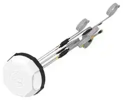
RF Antenna, Linear/RHC, 6 to 7.125 GHz, 3G/4G/5G/Cellular/CBRS/GNSS/ISM/LTE/Wi-Fi 6E, 6dBi, 2 VSWR
- Manufacturer: TE CONNECTIVITY
- Product type:
- Gain: 6dBi
- SVHC: No SVHC (27-Jun-2024)
- VSWR: 2
- Input Power: 10W
- Antenna Type: 3G / 4G / 5G / Cellular / CBRS / GNSS / ISM / LTE / Wi-Fi 6E
- Frequency Max: 7.125GHz
- Frequency Min: 6GHz
- Product Range: -
- Input Impedance: 50ohm
- Antenna Mounting: Stud Mount / RP SMA / SMA Connector
- Antenna Polarisation: Right Hand Circular, Linear
| Delivery and price | |
|---|---|
| Units per pack | 1 |
| Price | 452.68 € |
| Current stock | 10+ |
| Lead time | 30 days |
## **FP40 ULTRA 4X4 MIMO ANTENNAS INTELLIGENT TRANSPORTATION**

Datasheet & Kit Configuration Guide

## **FP40 ULTRA 4X4 MIMO VEHICULAR ANTENNAS**

FP40 ultra antennas provide an all-in-one solution for LTE/5G, Wi-Fi, GNSS and Bluetooth in high bandwidth mobile connectivity applications.

The product family includes multi-port solutions up to 14-ports, along with a range of connector options to suit all major vehicular gateways and routers.

## **FEATURES AND BENEFITS**

- Configurations available up to 14-ports incorporating next-generation technology

- 4G, 5G, CBRS, Wi-Fi, Bluetooth, GNSS coverage from a single antenna

- Designed for applications demanding the highest data rates and lowest latency

- Future-proofed against future 4G and 5G frequency roll outs up to 7125 MHz

- Compatible with all gateways & routers from major manufacturers

- Customizable connector, cable length and port configurations

- R118 compliant cables

- Stylish and aesthetic design

## **KEY DIFFERENTIATORS**

- Low profile design, 66.5mm height, for improved vehicle clearance

- L1 and L5 GNSS for improved positioning accuracy and response times

- Out of band rejection filters maintain consistent performance

- High data throughput is enabled by technologies such as carrier aggregation

- Coverage of all 4G and 5G bands (617-7125 MHz), CBRS, Wi-Fi, Bluetooth and GNSS

- Superior gain patterns, low gain ripple, high gain at horizon and efficiency over 70%

- UV, flammability, humidity, impact, vibration, shock certified

- IP67 and IP69K rated for improved durability

## **TABLE OF CONTENTS**

- FP40 ultra kit overview

- FP40 ultra kit configurations

- FP40 ultra specifications

- FP40 ultra radiation patterns

- FP40 ultra packaging & drawings

- FP40 ultra example applications

DATA AND DEVICES / FP40 ULTRA CONFIGURATION GUIDE

2

## **FP40 ULTRA 4X4 MIMO: ANTENNA OVERVIEW**

**==> picture [527 x 598] intentionally omitted <==**

**----- Start of picture text -----**<br>
2<br>1 Port Options:<br>4 Port<br>8 Port<br>9 Port<br>14 Port<br>2 Color Options:<br>1<br>Black<br>White<br>Extension Cable<br>3<br>Connector Options:<br>SMA<br>RP-SMA<br>TNC<br>QMA<br>FAKRA<br>3<br>And More<br>EXAMPLES OF CONNECTOR TERMINATIONS ON EXTENSION CABLES<br>FAKRA QMA RP SMA SMA TNC Extension Cables<br>All kits are supplied with a 5m extension<br>cable set as standard (see pages 4-5<br>for standard extension cable connector<br>options). Custom configurations are<br>available on request.<br>Connectors will be individually marked<br>with an appropriate label which is color<br>coded to guide installers in connecting<br>extension cables to the correct port on<br>the router or gateway device.<br>4G/5G GNSS BT<br>WLAN<br>A AD<br>DATA AND DEVICES / FP40 ULTRA CONFIGURATION GUIDE 3<br>**----- End of picture text -----**<br>


## **FP40 ULTRA 4X4 MIMO: KIT CONFIGURATIONS**

The table below shows common examples of the FP40 ultra kit configurations and the part numbers used to order these kits. Other options are available on request.

All kits are supplied with 5 meter (16 ft.) extension cables attached as standard. If you require different extension cable lengths or connector configurations please contact us to discuss your options.

|FP40 ultra Kit|Port Configuration|Frequency (MHz)|Extension Cable<br>Connector|
|---|---|---|---|
|4 Port - Kit Part No. - L000434-07||||
|SMA Male x 4<br>**+**<br>~~:~~|4G/5G Port x 4|617-960; 1427-1511;<br>1690-2700; 3300-7125|SMA Male x 4|
|7 Port - Kit Part No. - L000434-09<br>~~:~~||||
|SMA Male x 4<br>SMA Male x 1<br>RP-SMA Male x 2<br>**+**<br>~~:~~<br>~~_~~|4G/5G Port x 4<br>~~_~~|617-960; 1427-1511;<br>1690-2700; 3300-7125|SMA Male x 4|
||WLAN Port x 2|2400-2500; 4900-7125|RP-SMA Male x 2|
||GNSS Port x 1|1427-1511 (L1 & L5)|SMA Male x 1|
|8 Port Option 1 - Kit Part No. - L000434-04<br>||||
|SMA Male x 4<br>SMA Male x 1<br>SMA Male x 1<br>RP-SMA Male x 2<br>**+**<br>~~:~~|4G/5G Port x 4|617-960; 1427-1511;<br>1690-2700; 3300-7125|SMA Male x 4|
||WLAN Port x 2|2400-2500; 4900-7125|RP-SMA Male x 2|
||GNSS Port x 1|1427-1511 (L1 & L5)|SMA Male x 1|
||Bluetooth x 1|2400-2500|SMA Male x 1|
|8 Port Option 2 - Kit Part No. - L000434-05<br>~~:~~||||
|**+**<br>FAKRA D x 4<br>FAKRA Z x 1<br>FAKRA C x 1<br>FAKRA I x 2<br>~~:~~|4G/5G Port x 4|617-960; 1427-1511;<br>1690-2700; 3300-7125|FAKRA D x 4|
||WLAN Port x 2|2400-2500; 4900-7125|FAKRA I x 2|
||GNSS Port x 1|1427-1511 (L1 & L5)|FAKRA C x 1|
||Bluetooth x 1|2400-2500|FAKRA Z x 1|


DATA AND DEVICES / FP40 ULTRA CONFIGURATION GUIDE

4

|FP40 ultra Kit|Port Configuration|Frequency (MHz)|Extension Cable<br>Connector|
|---|---|---|---|
|8 Port Option 3 - Kit Part No. - L000434-06||||
|SMA Male x 4<br>SMA Male x 1<br>SMA Male x 1<br>RP-SMA Male x 2<br>**+**<br>~~.——~~|4G/5G Port x 4|617-960; 1427-1511;<br>1690-2700; 3300-7125|SMA Male x 4|
||WLAN Port x 2|2400-2500; 4900-7125|RP-SMA Male x 2|
||GNSS Port x 1|1427-1511 (L1 & L5)|SMA Male x 1|
||Bluetooth x 1|2400-2500|SMA Male x 1|
|9 Port Option 1 - Kit Part No. - L000434-01<br>~~.——~~||||
|SMA Male x 4<br>SMA Male x 1<br>RP-SMA Male x 4<br>**+**<br>~~. ——~~<br>~~-OO~~|4G/5G Port x 4|617-960; 1427-1511;<br>1690-2700; 3300-7125|SMA Male x 4|
||WLAN Port x 4|2400-2500; 4900-7125|RP-SMA Male x 4|
||GNSS Port x 1|1427-1511 (L1 & L5)|SMA Male x 1|
|9 Port Option 2 - Kit Part No. - L000434-02<br>~~-OO~~||||
|**+**<br>FAKRA D x 4<br>FAKRA C x 1<br>FAKRA I x 4<br>~~- OO~~<br>—|4G/5G Port x 4|617-960; 1427-1511;<br>1690-2700; 3300-7125|FAKRA D x 4|
||WLAN Port x 4|2400-2500; 4900-7125|FAKRA I x 4|
||GNSS Port x 1|1427-1511 (L1 & L5)|FAKRA C x 1|
|9 Port Option 3 - Kit Part No. - L000434-03||||
|**+**<br>SMA Male x 4<br>SMA Male x 1<br>RP-SMA Male x 4|4G/5G Port x 4|617-960; 1427-1511;<br>1690-2700; 3300-7125|SMA Male x 4|
||WLAN Port x 4|2400-2500; 4900-7125|RP-SMA Male x 4|
||GNSS Port x 1|1427-1511 (L1 & L5)|SMA Male x 1|
|14 Port - Kit Part No. - L000434-08||||
|SMA Male x 4<br>SMA Male x 1<br>SMA Male x 1<br>RP-SMA x 8<br>**+**<br>:|4G/5G Port x 4|617-960; 1427-1511;<br>1690-2700; 3300-7125|SMA Male x 4|
||WLAN Port x 8|2400-2500; 4900-7125|RP-SMA Male x 8|
||GNSS Port x 1|1427-1511 (L1 & L5)|SMA Male x 1|
||Bluetooth x 1|2400-2500|SMA Male x 1|


For ease of installation, high-port count antenna kits may not have all extension cables pre-attached.

DATA AND DEVICES / FP40 ULTRA CONFIGURATION GUIDE

5

## **FP40 ULTRA 4X4 MIMO: SPECIFICATIONS**

The following specifications are representative of all models/port options in the FP40 ultra antenna family. Unless stated the data includes testing of the antenna only and does not include testing with a 5 meter (16 feet) extension cable. For more detailed information please contact us.

- ELECTRICAL SPECIFICATION - 4G/5G/CBRS (CELLULAR), WI-FI & BLUETOOTH

- ~~|~~

|ELECTRICAL SPECIFICATION - 4G/5G/CBRS (CELLULAR), WI-FI & BLUETOOTH<br>~~|~~|ELECTRICAL SPECIFICATION - 4G/5G/CBRS (CELLULAR), WI-FI & BLUETOOTH<br>~~|~~|ELECTRICAL SPECIFICATION - 4G/5G/CBRS (CELLULAR), WI-FI & BLUETOOTH<br>~~|~~|ELECTRICAL SPECIFICATION - 4G/5G/CBRS (CELLULAR), WI-FI & BLUETOOTH<br>~~|~~|ELECTRICAL SPECIFICATION - 4G/5G/CBRS (CELLULAR), WI-FI & BLUETOOTH<br>~~|~~|ELECTRICAL SPECIFICATION - 4G/5G/CBRS (CELLULAR), WI-FI & BLUETOOTH<br>~~|~~|ELECTRICAL SPECIFICATION - 4G/5G/CBRS (CELLULAR), WI-FI & BLUETOOTH<br>~~|~~|ELECTRICAL SPECIFICATION - 4G/5G/CBRS (CELLULAR), WI-FI & BLUETOOTH<br>~~|~~|ELECTRICAL SPECIFICATION - 4G/5G/CBRS (CELLULAR), WI-FI & BLUETOOTH<br>~~|~~|ELECTRICAL SPECIFICATION - 4G/5G/CBRS (CELLULAR), WI-FI & BLUETOOTH<br>~~|~~|ELECTRICAL SPECIFICATION - 4G/5G/CBRS (CELLULAR), WI-FI & BLUETOOTH<br>~~|~~|
|---|---|---|---|---|---|---|---|---|---|---|
|~~|~~|4G/5G/CBRS (Cellular)<br>~~|~~||||||Wi-Fi<br>~~|~~|||Bluetooth<br>~~|~~|
|Operating Frequency (MHz)|617-<br>960|1427-<br>1511|1690-<br>2700|3300-<br>4200|4400-<br>6000|6000-<br>7125|2400-<br>2500|4900-<br>6000|6000-<br>7125|2400-2500|
|Peak Gain - Max (dBi)*|4.0|8.0|||9.0|7.0|7.5|8.5|9.5|6.0|
|Total Efficiency Average (%)*|42|41|61|61|54|49|50|51|53|54|
|Isolation - Cellular-to-Cellular/<br>Bluetooth Elements (dB)**|13|21|20|26|34|38|N/A|||22|
|Isolation - Wi-Fi-to-Wi-Fi<br>Elements (dB)**|N/A||||||22|22|27|N/A|
|Max Power @ Ambient 20°C<br>(Watts)|10||||||1||||
|Nominal Impedance (Ohms)|50||||||||||
|Polarization|Linear||||||||||
|Azimuth Beamwidth|360°, Omnidirectional||||||||||


*Measured with 0.3m (1 ft) coax cable

**Measured with 0.3m (1 ft) pigtail + 5m (16ft) 0.195” diameter extension cable

|ELECTRICAL SPECIFICATION - GNSS***<br>~~eee~~|ELECTRICAL SPECIFICATION - GNSS***<br>~~eee~~|ELECTRICAL SPECIFICATION - GNSS***<br>~~eee~~|ELECTRICAL SPECIFICATION - GNSS***<br>~~eee~~|ELECTRICAL SPECIFICATION - GNSS***<br>~~eee~~|
|---|---|---|---|---|
|Number of Ports<br>~~eee~~|1<br>~~eee~~||||
|Frequency (MHz)|L1 Band|||L5 Band|
||1561|1575.42|1602|1176.45|
|Patch/Passive Antenna Peak<br>Gain (dBi)|-0.6|0.9|-0.5|-0.4|
|LNA Gain (dBi)|28±3||||
|Noise Figure (dB)|< 3||||
|Input Max Power (dBm)|+10||||
|Nominal Impedance (Ohms)|50||||
|Out of Band Rejection (dBc)|350-520 MHz|||> 65|
||698-960 MHz|||> 70|
||1428-1511 MHz|||> 40|
||1710-2700 MHz|||> 65|
||4900-5800 MHz|||> 75|
|DC Voltage (V)|2-5||||
|Current (mA)|12.5 Typ. (at DC 3.0V)||||


***Measured on 0.6 x 0.6m (2 x 2ft) ground plane

DATA AND DEVICES / FP40 ULTRA CONFIGURATION GUIDE

6

|EXTENSION CABLE ATTENUATION FIGURES - 5MM (0.195 INCH) CABLES|EXTENSION CABLE ATTENUATION FIGURES - 5MM (0.195 INCH) CABLES|EXTENSION CABLE ATTENUATION FIGURES - 5MM (0.195 INCH) CABLES|EXTENSION CABLE ATTENUATION FIGURES - 5MM (0.195 INCH) CABLES|EXTENSION CABLE ATTENUATION FIGURES - 5MM (0.195 INCH) CABLES|EXTENSION CABLE ATTENUATION FIGURES - 5MM (0.195 INCH) CABLES|EXTENSION CABLE ATTENUATION FIGURES - 5MM (0.195 INCH) CABLES|EXTENSION CABLE ATTENUATION FIGURES - 5MM (0.195 INCH) CABLES|EXTENSION CABLE ATTENUATION FIGURES - 5MM (0.195 INCH) CABLES|EXTENSION CABLE ATTENUATION FIGURES - 5MM (0.195 INCH) CABLES|EXTENSION CABLE ATTENUATION FIGURES - 5MM (0.195 INCH) CABLES|EXTENSION CABLE ATTENUATION FIGURES - 5MM (0.195 INCH) CABLES|
|---|---|---|---|---|---|---|---|---|---|---|---|
|Frequency Range (MHz)|698|960|1511|2500|2700|3300|4200|4400|4900|6000|7125|
|Cable Attenuation (dB/m)|< 0.3|< 0.4|< 0.5|< 0.7|< 0.7|< 0.8|< 0.9|< 1.0|< 1.1|< 1.2|< 1.3|


## MECHANICAL SPECIFICATION

|MECHANICAL SPECIFICATION|MECHANICAL SPECIFICATION|
|---|---|
|Installed Dimensions H x Dia mm (in.)|66.5 x 187 (2.62 x 7.4)|
|Max Weight – g (oz.)<br>- Not Including Extension Cables|479 (16.9) - 612 (21.59) - Dependent on Model|
|Number of Ports|4 to 14 Port Options Available|
|Mounting Type|Fixed Stud M20|
|Radome|Polycarbonate, UL94-V0|
|Baseplate Material|Aluminium|


|ENVIRONMENTAL SPECIFICATION|ENVIRONMENTAL SPECIFICATION|
|---|---|
|Operating Temperature – °C (°F)|-40 to +85 (-40 to +185)|
|Storage Temperature – °C (°F)|-40 to +85 (-40 to +185)|
|Ingress Protection|IP67, IP69K|
|UV Rating|ASTM D4674|
|Flammability Rating|Radome: UL94 V0<br>Cable: UN ECE R118|
|Mechanical Shock Rating|IEC 60068-2-27, Secured Cross Country Vehicles|
|Vibration Test Rating|MIL-STD-810G, Method 514.6, Category 4, Highway Truck Vibration|
|Humidity Rating|MIL-STD-810G, 507.5, Procedure II, Aggravated Humidity @ 95%|
|Material Substance Compliance|RoHS Compliant<br>CE & UKCA Compliant - Antenna|


DATA AND DEVICES / FP40 ULTRA CONFIGURATION GUIDE

7

## **GLOBAL 4G, 5G, CBRS CELLULAR COVERAGE**

The FP40 ultra antenna family provides truly global cellular coverage. The table below shows the frequencies and bands covered and the corresponding performance across those bands is shown in the charts below.

|FREQUENCY|RF BANDS COVERED|
|---|---|
|617-698 MHz|71|
|698-960 MHz|5, 6, 8, 12, 13, 14, 17, 18, 19, 20, 26, 27, 28, 29, 44, 67, 68, 85<br>N5, N8, N12, N14, N18, N20, N28, N29, N81, N82, N83, N89, N91, N92, N93, N94|
|1427-1511 MHz|11, 21, 32, 45, 74<br>N50, N51, N74, N75, N76|
|1690-2700 MHz|1, 2, 3, 4, 7, 9, 10, 15, 16, 23, 25, 30, 33, 34, 35, 36, 37, 38, 39, 40, 41, 65, 66, 69, 70<br>N30, N34, N38, N39, N40, N41, N65, N66, N70, N80, N84, N86, N90, N95|
|3300-4200 MHz|22, 42, 43, 48<br>N48, N77, N78|
|4400-6000 MHz|N79|
|6000-7125 MHz*|46, 47<br>N96, N102, N104|


## **4G, 5G, CBRS CELLULAR PERFORMANCE**

TYPICAL VSWR

DATA AND DEVICES / FP40 ULTRA CONFIGURATION GUIDE

8

## **4G, 5G, CBRS CELLULAR PERFORMANCE**

## GAIN MAX (DBI)

**==> picture [512 x 200] intentionally omitted <==**

**----- Start of picture text -----**<br>
10<br>9<br>8<br>7<br>6<br>5<br>4<br>3<br>2<br>1<br>0<br>Max Gain<br>617 698 710 725 746 776 806 850 880 948 1427 1525 1580 1720 1755 1880 1950 1990 2130 2170 2412 2700 3500 3800 4100 4400 4700 5000 5250 5470 5600 5780 5875 5950 6100 6425 6600 6875<br>**----- End of picture text -----**<br>


## AVERAGE EFFICIENCY

**==> picture [527 x 215] intentionally omitted <==**

**----- Start of picture text -----**<br>
70%<br>60%<br>50%<br>40%<br>30%<br>20%<br>10%<br>0%<br>Average Efficiency<br>617 698 710 725 746 776 806 850 880 948 1350 1500 1575 1710 1740 1850 1930 1970 2120 2155 2310 2600 3400 3700 4000 4300 4600 4900 5150 5400 5500 5650 5800 5875 5950 6100 6425 6600 6875<br>**----- End of picture text -----**<br>


DATA AND DEVICES / FP40 ULTRA CONFIGURATION GUIDE

9

## **WI-FI AND BLUETOOTH PERFORMANCE**

**==> picture [354 x 34] intentionally omitted <==**

**----- Start of picture text -----**<br>
Key<br>2400-2500 MHz 4900-6000 MHz 6000-7125 MHz<br>**----- End of picture text -----**<br>


## TYPICAL VSWR - WI-FI

**==> picture [442 x 559] intentionally omitted <==**

**----- Start of picture text -----**<br>
5<br>4<br>3<br>2<br>1<br>2000 2400 2800 3200 3600 4000 4400 4800 5200 5600 6000 6400 6800 7200<br>Frequency, MHz<br>Wi-Fi: 1ft RG174LL Wi-Fi: 1ft RG174LL+16ft RG58LL<br>GAIN MAX (DBI) - WI-FI<br>10<br>9<br>8<br>7<br>6<br>5<br>4<br>3<br>2<br>1<br>0<br>Max Gain<br>AVERAGE EFFICIENCY - WI-FI<br>70%<br>60%<br>50%<br>40%<br>30%<br>20%<br>10%<br>0%<br>Average Efficiency<br>2400 2500 4900 6000 7125<br>VSWR<br>2400 2410 2420 2430 2440 2450 2460 2470 2480 2490 2500 4900 4950 5000 5050 5100 5150 5200 5250 5300 5350 5400 5450 5500 5550 5600 5650 5700 5750 5800 5850 5875 5900 5950 6000 6100 6200 6300 6425 6475 6525 6600 6700 6800 6875 7000 7125<br>2400 2410 2420 2430 2440 2450 2460 2470 2480 2490 2500 4900 4950 5000 5050 5100 5150 5200 5250 5300 5350 5400 5450 5500 5550 5600 5650 5700 5750 5800 5850 5875 5900 5950 6000 6100 6200 6300 6425 6475 6525 6600 6700 6800 6875 7000 7125<br>**----- End of picture text -----**<br>


## GAIN MAX (DBI) - WI-FI

## AVERAGE EFFICIENCY - WI-FI

DATA AND DEVICES / FP40 ULTRA CONFIGURATION GUIDE

10

## **FP40 ULTRA 4X4 MIMO: RADIATION PATTERNS**

The patterns below are representative of the typical performance of all FP40 ultra 4x4 MIMO antenna models. Patterns are recorded without the extension cable added and are four element (cellular) or up to eight element (Wi-Fi) simulated composite data. Please contact us for full test data. These antennas will perform on and off a ground plane. Performance may vary slightly when no ground plane is used in conjunction with these antennas. If you require test data for both scenarios please get in touch.

4G/5G/CBRS (CELLULAR)

## Radiation Patterns at 617 MHz

## Radiation Patterns at 698 MHz

Radiation Patterns at 850 MHz

## Radiation Patterns at 960 MHz

Radiation Patterns at 1500 MHz

## Radiation Patterns at 1690 MHz

DATA AND DEVICES / FP40 ULTRA CONFIGURATION GUIDE

11

## Radiation Patterns at 1850 MHz

## Radiation Patterns at 2500 MHz

## Radiation Patterns at 3500 MHz

## Radiation Patterns at 6000 MHz

## Radiation Patterns at 2170 MHz

## Radiation Patterns at 2700 MHz

## Radiation Patterns at 4900 MHz

Radiation Patterns at 7125 MHz

DATA AND DEVICES / FP40 ULTRA CONFIGURATION GUIDE

12

## WI-FI & BLUETOOTH

## Radiation Patterns at 2400 MHz

## Radiation Patterns at 2500 MHz

## Radiation Patterns at 5500 MHz

## Radiation Patterns at 2450 MHz

## Radiation Patterns at 4900 MHz

## Radiation Patterns at 6000 MHz

## Radiation Patterns at 7125 MHz

DATA AND DEVICES / FP40 ULTRA CONFIGURATION GUIDE

13

## **FP40 ULTRA 4X4 MIMO: DRAWINGS**

MECHANICAL DRAWINGS

Installed/Compressed Height - 66.5mm (2.62 in.) * + * H = 69.9mm (2.75 in.) From Bottom Gasket _—4;S ** H = 68mm (2.68 in.) From Bottom Foam

## **PACKAGING**

FP40 ultra antennas will be shipped with the appropriate extension cable, in the kit configurations on pages 4-5 of this document. Extension cables will be pre-fitted to the antenna pigtail to reduce installation time. Shipping weights for each kit part number are shown below and quantities and dimensions on the following page.

|Kit Part<br>Number|Description|Color|Estimated Master<br>Carton Weight<br>Kg (lbs)|Air Shipment<br>Estimated Pallet<br>Weight<br>Kg (lbs)|Ocean Shipment<br>Estimated Pallet<br>Weight<br>Kg (lbs)|
|---|---|---|---|---|---|
|L000434-01|9 Port: 4 x Cellular, 4 x Wi-Fi, 1 x GNSS|Black|2.75 (6.06)|149.5 (329.59)|204.5 (450.85)|
|L000434-02|9 Port: 4 x Cellular, 4 x Wi-Fi, 1 x GNSS|Black|2.75 (6.06)|149.5 (329.59)|204.5 (450.85)|
|L000434-03|9 Port: 4 x Cellular, 4 x Wi-Fi, 1 x GNSS|White|2.75 (6.06)|149.5 (329.59)|204.5 (450.85)|
|L000434-04|8 Port: 4 x Cellular, 2 x Wi-Fi, 1 x Bluetooth, 1 x GNSS|Black|2.55 (5.62)|139.5 (307.55)|190.5 (419.98)|
|L000434-05|8 Port: 4 x Cellular, 2 x Wi-Fi, 1 x Bluetooth, 1 x GNSS|Black|2.55 (5.62)|139.5 (307.55)|190.5 (419.98)|
|L000434-06|8 Port: 4 x Cellular, 2 x Wi-Fi, 1 x Bluetooth, 1 x GNSS|White|2.55 (5.62)|139.5 (307.55)|190.5 (419.98)|
|L000434-07|4 Port: 4 x Cellular|Black|3.40 (7.50)|114  (251.32)|165 (363.76)|
|L000434-08|14 Port: 4 x Cellular, 8 x Wi-Fi, 1 x Bluetooth, 1 x GNSS|Black|3.76 (8.29)|200 (440.93)|275.2 (606.71)|
|L000434-09|7 Port: 4 x Cellular, 2 x Wi-Fi, 1 x GNSS|White|2.55 (5.62)|139.5 (307.55)|190.5 (419.98)|


DATA AND DEVICES / FP40 ULTRA CONFIGURATION GUIDE

14

## **PACKAGING DIMENSIONS & QUANTITY**

## 7-14 PORT KIT PACKAGING

## **Air Pallet**

## **Ocean Pallet Master Carton**

**==> picture [102 x 26] intentionally omitted <==**

**----- Start of picture text -----**<br>
Master Carton Packaging<br>1 x Antenna with Extension Cable<br>Included<br>**----- End of picture text -----**<br>


**==> picture [247 x 77] intentionally omitted <==**

**----- Start of picture text -----**<br>
Included<br>a SSH Ls<br>**----- End of picture text -----**<br>


AIR SHIPMENT

- 1 ANTENNA PER MASTER CARTON

- 10 CARTONS PER LAYER

- 5 LAYERS PER PALLET

- TOTAL ANTENNAS PER PALLET = 50 PCS

OCEAN SHIPMENT

- 1 ANTENNA PER MASTER CARTON

- 10 CARTONS PER LAYER

- 7 LAYERS PER PALLET

- TOTAL ANTENNAS PER PALLET = 70 PCS

## 4 PORT KIT PACKAGING

## **Air Pallet**

**Ocean Pallet**

## **Master Carton**

Master Carton Packaging 3 x Antenna with Extension Cable Included .

AIR SHIPMENT

- 3 ANTENNAS PER MASTER CARTON

- 5 CARTONS PER LAYER

- 6 LAYERS PER PALLET

OCEAN SHIPMENT

   - 3 ANTENNAS PER MASTER CARTON

   - 5 CARTONS PER LAYER

   - 9 LAYERS PER PALLET

- TOTAL ANTENNAS PER PALLET = 90 PCS • TOTAL ANTENNAS PER PALLET = 135 PCS

DATA AND DEVICES / FP40 ULTRA CONFIGURATION GUIDE

15

## **FP40 ULTRA 4X4 MIMO: APPLICATIONS**

The examples below are intended to demonstrate just some of the scenarios and applications where FP40 ultra antennas may be used. There are many more possible scenarios and applications. If you are in any doubt about whether this is the correct antenna for your use, please contact us.

## **Public Transportation**

On board connectivity is not only common but expected nowadays. In fact after arriving on time, a passenger’s second concern is likely to be whether they can stream their favorite music and shows on the move. Other than on board Wi-Fi, applications for public transportation can also include: ticketing (digital payments or apps); navigation systems; security cameras; dispatch control; vehicle diagnostics etc.

## **Emergency Services & Public Safety**

Emergency services and public safety agencies around the world have an ever increasing need for high bandwidth data connectivity with applications such as: dash cam footage; live video streaming; ANPR; facial recognition; finger print analysis etc..

## **Utility & Repair Vehicles**

Utility and repair vehicles often utilize a wide variety of connectivity in order to operate effectively including devices communicating with the vehicle through Wi-Fi, cloud uploads via 5G and location through GNSS. These requirements can be seen in the: diagnostic equipment; augmented reality (AR); live video streaming; software updates; and positioning/location services used on a daily basis.

## **te.com**

TE Connectivity, TE Connectivity (logo) and TE are trademarks. All other logos, products and/or company names referred to herein might be trademarks of their respective owners.

The information given herein, including drawings, illustrations and schematics which are intended for illustration purposes only, is believed to be reliable. However, TE Connectivity makes no warranties as to its accuracy or completeness and disclaims any liability in connection with its use. TE Connectivity‘s obligations shall only be as set forth in TE Connectivity‘s Standard Terms and Conditions of Sale for this product and in no case will TE Connectivity be liable for any incidental, indirect or consequential damages arising out of the sale, resale, use or misuse of the product. Users of TE Connectivity products should make their own evaluation to determine the suitability of each such product for the specific application.

©2023 TE Connectivity. All Rights Reserved.

**03/23   Original**

## **TECHNICAL SUPPORT CENTER**

USA: +1 (800) 522-6752 Canada: +1 (905) 475-6222 Mexico: +52 (0) 55-1106-0800 Latin/S. America: +54 (0) 11-4733-2200 Germany: +49 (0) 6251-133-1999 UK: +44 (0) 800-267666 France: +33 (0) 1-3420-8686 Netherlands: +31 (0) 73-6246-999 China: +86 (0) 400-820-6015

DATA AND DEVICES / FP40 ULTRA CONFIGURATION GUIDE
Updated at June 9, 2026
TE Connectivity is a globally recognized engineering and manufacturing leader, specializing in highly reliable connectivity and sensing solutions. Renowned for innovation and durability, their components are engineered to perform in the most demanding environments, supporting critical advancements in industrial equipment, data communications, and automotive systems. Our extensive selection of TE Connectivity products is anchored by their industry-leading connector portfolio. We carry a comprehensive array of terminal blocks and accessories, including wire-to-board, pluggable, standard, and barrier configurations, alongside robust backplane connectors designed to ensure secure and efficient power and data transmission in complex circuit designs. Beyond physical connections, TE Connectivity is a premier manufacturer of precision sensors, antennas, and electromechanical switching components. Our inventory features a wide variety of RF antennas and highly accurate pressure, temperature, and force transducers. Additionally, we provide an expansive range of TE's dependable relays, encompassing automotive, power, and signal variants, alongside essential passive components like shielding gaskets and RF inductors to fully support your engineering requirements.
About Novapart
Novapart is a B2B electronic component broker specialising in stock shortages and cost reduction. We source hard-to-find parts and identify compliant alternatives across a catalogue of 410,000+ components from 500+ manufacturers.
Learn more →Stock Shortage Specialist
When a component is unavailable, discontinued or has an unacceptable lead time, we tap into our network of vetted European and Asian distributors to source what you need — without compromising on quality or traceability.
Request a quote →Compliant Alternatives
We identify pin-to-pin, electrically equivalent substitutes that meet the same certifications (RoHS, AEC-Q100, REACH) as your original specification — validated against datasheets, not just part numbers. Often at a lower cost.
BOM Analysis service →