
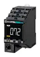


K6CM-VBMD-EIP
MOTOR MONITORING DEVICE, 14MM, 24V
- Manufacturer: OMRON INDUSTRIAL AUTOMATION
- Product type: Digital Panel Meters
- No. of Digits / Alpha:-; Meter Function:Multifunction; Meter Range:-; Digit Height:14mm; Panel Cutout Height:-; Panel Cutout Width:-; Supply Voltage Min:-; Supply Voltage Max:24V 71AC4
| Delivery and price | |
|---|---|
| Units per pack | 1 |
| Price | 2531.7 € |
| Current stock | 10+ |
| Lead time | 30 days |
## **Motor Condition Monitoring Device K6CM-CI** ## **24/7 monitoring of motor overload conditions.** - The “comprehensive current diagnosis” can monitor not only for motor problems, but also abnormal load-side conditions. - Simply install a CT on the control panel enables monitoring. - The software tool (set-up and simple monitoring tool) is also provided. - K6CM-CI2M is newly added. This model is suitable for use in an excessive noise environment such as using an inverter. Supports Modbus TCP in addition to EtherNet/IP. For the most recent information on models that have been certified for safety standards, refer to your OMRON website. ## **System Configuration** ## **Basic Configuration** **Comprehensive current diagnosis type (K6CM-CI)** **==> picture [442 x 257] intentionally omitted <==** **----- Start of picture text -----**<br> * 1<br>Three-phase<br>power supply<br>K6CM-CIC (CT)<br>Any type of<br>Single-phase single-phase<br>power supply measurement * 3<br>2.9 m<br>Measurement<br>trigger signal (pre-wired cable) * 4<br>Object monitored<br>_ 1.5 kW to 300 kW (400 V)<br>Output signal<br>K6CM-CI 0.75 kW to 150 kW (200 V)<br>By keeping a computer or PLC (transistor output)<br>continuously connected, you can<br>monitor the state of a motor.<br>Built-in EtherNet/IP port<br>Dedicated tool<br>EtherNet/IP<br>LAN Modbus TCP * 2<br>Note : 1. Even without a computer, the alarm bar of the main unit notifies you of changes of motor state.<br>2. The degradation level may appear differently depending on the failure condition of the motor<br>or load, or depending on the installation condition.<br>**----- End of picture text -----**<br> ## **Using a K6CM-CIM** - *1. When the motor is driven by an inverter, it may not be possible to monitor the motor or load abnormalities. Refer to the User's manual (N219) for details. - *2. Modbus TCP is not supported. - *4. The CT cable cannot be extended. ## **Using a K6CM-CI2M** - *1. In an environment where the motor is driven by an inverter, if the degradation level 1 is used as the measurement value, it may not be possible to monitor the motor or load abnormalities. Therefore, it is recommended to use the degradation level 2. Refer to the User's manual (N219) for details. - *3. Since the frequency band of the harmonics of the drive frequency and the frequency band in which errors such as load imbalance and misalignment appear are the same frequency band for a 2-pole meter, sensitivity may be reduced with degradation level 2. - *4. The CT cable cannot be extended. **1** **K6CM-CI** ## **Ordering Information** ## **List of Models** |**Monitoring type**|**Degradation level/**<br>**Degradation level 1**|**Degradation level 2**|**Power supply voltage**|**Model**| |---|---|---|---|---| |Comprehensive current<br>diagnosis type|||100 to 240 VAC|**K6CM-CI2MA-EIP**| ||||24 VAC/VDC|**K6CM-CI2MD-EIP**| ||||100 to 240 VAC|**K6CM-CIMA-EIP**| ||||24 VAC/VDC|**K6CM-CIMD-EIP**| **Note:** The K6CM-CIM measures the feature value of the degradation level, and the K6CM-C12M measures the feature values of degradation level 1 and degradation level 2. The degradation level of the K6CM-CIM is the same as degradation level 1. For the differences of each, refer to the User's Manual (N219). ## **CT (Order separately)** |**Rated primary-side current**|**Applicable Relay**<br>~~Ce~~|**Model**| |---|---|---| |5 A|K6CM-CI|**K6CM-CICB005**| |25 A||**K6CM-CICB025**| |100 A||**K6CM-CICB100**| |200 A||**K6CM-CICB200**| |400 A||**K6CM-CICB400**| |600 A||**K6CM-CICB600**| **Note:** One sensor is combined with one main unit. A cable for connection is provided with the CT. Select a CT that sets the current of the applicable motor within the measurement range. To calculate the current, refer to _Comprehensive Current Diagnosis Type Technical Data (Reference)_ on page 10. ## **EtherNet/IP communications cable recommended parts** Use a Category 5 or higher STP cable (shielded twisted pair cable). ## **Cable with Connectors** |*1.Cables with standard RJ45 plugs are available in the following lengths: 0.2 m, 0.3 m, 0.5 m, 1 m, 1.5 m, 2 m, 3 m, 5 m, 7.5 m, 10 m, 15 m, 20 m.<br>**Item**<br>**Recommended**<br>**manufacturer**<br>**Cable length (m)**<br>**Model**<br>Wire Gauge and Number of Pairs:<br>AWG26, 4-pair Cable<br>Cable Sheath material: LSZH*2<br>Cable with Connectors on Both Ends (RJ45/RJ45)<br>Standard RJ45 plug type*1<br>Cable color: Yellow*3<br>OMRON<br>**0.3**<br>**XS6W-6LSZH8SS30CM-Y**<br>**0.5**<br>**XS6W-6LSZH8SS50CM-Y**<br>**1**<br>**XS6W-6LSZH8SS100CM-Y**<br>**2**<br>**XS6W-6LSZH8SS200CM-Y**<br>**3**<br>**XS6W-6LSZH8SS300CM-Y**<br>**5**<br>**XS6W-6LSZH8SS500CM-Y**<br>Wire Gauge and Number of Pairs:<br>AWG22, 2-pair Cable<br>Cable with Connectors on Both Ends (RJ45/RJ45)<br>Rugged RJ45 plug type*1<br>Cable color: Light blue<br>OMRON<br>**0.3**<br>**XS5W-T421-AMD-K**<br>**0.5**<br>**XS5W-T421-BMD-K**<br>**1**<br>**XS5W-T421-CMD-K**<br>**2**<br>**XS5W-T421-DMD-K**<br>**5**<br>**XS5W-T421-GMD-K**<br>**10**<br>**XS5W-T421-JMD-K**<br>~~|~~<br>~~||sd~~<br>~~**|**~~<br>~~ag | E~~<br>~~4~~<br>~~—~~<br>~~sd~~<br>~~[||sd~~<br>_<br>~~|sd~~<br>~~ae_—~~<br>~~|~~| |---| |Cables with rugged RJ45 plugs are available in the following lengths: 0.3 m, 0.5 m, 1 m, 2 m, 3 m, 5 m, 10 m, 15 m.| |For details, refer to the_Industrial Ethernet Connectors Catalog_(Cat. No. G019).| |*2.The lineup features Low Smoke Zero Halogen cables for in-cabinet use and PUR cables for out-of-cabinet use.| |*3.Cable colors are available in yellow, green, and blue. The last character of the model changes to "-G" or "-B".| |**Cable/Connector**| |**Part name**<br>**Manufacturer**<br>**Model**| |Cable<br>Hitachi Metals, Ltd.<br>**NETSTAR-C5E SA 0.5 × 4P***| |RJ45 connector<br>Panduit Corporation<br>**MPS588-C***| |*It is recommended to use the cable and connector in combination described above.| |**Industrial switching hub (recommended parts)**| |**Product name**<br>**Appearance**<br>**Specifications**<br>**Model**<br>**Function**<br>**No. of ports**<br>**Failure detection**<br>**function**<br>Industrial switching hub<br>Priority control (QoS): EtherNet/IP control data<br>priority<br>Failure detection: Broadcast storm /<br>LSI failure detection<br>10/100BASE-TX, Auto-Negotiation<br>3<br>No<br>**W4S1-03B**<br>5<br>No<br>**W4S1-05B**<br>5<br>Yes<br>**W4S1-05C**<br>~~Ce~~<br>~~eees~~<br>~~esee~~<br>~~stFf~~| - *2. The lineup features Low Smoke Zero Halogen cables for in-cabinet use and PUR cables for out-of-cabinet use. **2** **K6CM-CI** ## **Ratings and Specifications** ## **List of Models** ## **Ratings** |**Power**<br>**Supply**|**Power supply voltage**|**Power supply voltage**|K6CM-@@MA: 100 to 240 VAC, 50/60 Hz<br>K6CM-@@MD: 24 VAC, 50/60 Hz, 24 VDC| |---|---|---|---| ||**Allowable operating voltage range**||85% to 110% of power supply voltage| ||**Power supply frequency range**||45 to 65 Hz| ||**Power consumption**||24 VAC/24 VDC: 3.2 VA/1.7 W max.<br>100 to 240 VAC: 6.1 VA max.*1| |**Input**|**Current,**<br>**comprehensive current**<br>**diagnosis (CT)**|**Rated input current**|5 A, 25 A, 100 A, 200 A, 400 A, 600 A| |**Applicable motor type**|||Three-phase induction motor (Rated voltage 480 VAC)*2| |**Outputs**|**Output form**||Transistor output| ||**Output capacity**||3-point| ||**Output rating**||Rated voltage: 24 VDC<br>Max. current: 50 mA, DC| |**Ambient operating temperature**|||-10 to +55°C (with no condensation or icing)| |**Storage temperature**|||-20 to +65°C (with no condensation or icing)| |**Ambient operating humidity**|||25% to 85% RH (with no condensation)| |**Storage humidity**|||25% to 85% RH (with no condensation)| |**Case color**|||Black| |**Case material**|||Polycarbonate UL94-V0| |**Altitude**|||2,000 m max.| |**Applicable wires**|||Stranded wires, solid wires, or ferrules| |**Applicable wire size**|||0.25 to 1.5 mm2(AWG24 to 16)| |**Wire insertion force**|||8 N max. (AWG20)| |**Screwdriver insertion force**|||15 N max.| |**Wire stripping length**|||8 mm| |**Recommended flat-blade screwdriver**|||XW4Z-00B (Omron)| |**Current capacity**|||10 A (per pole)| |**Number of insertions**|||50 times| |**Weight**|||Approx. 200 g| |**Mounting**|||Mounts to DIN Track<br>screw mounting| |**Dimensions**|||45 (W) × 90 (H) × 90 (D) mm| |**Setting method**|||Communications settings from a dedicated tool via EtherNet/IP| |**Other functions**|||Display value selection, self-diagnosis error output, setting value initialization, operation integration| |**Accessories**|||Operation manual, CD-ROM (Motor condition monitoring Tool)| *1. Value of the K6CM-C12M. On the K6CM-CIM, 3.1 VA or less/1.6 W or less with AC 24/DC 24, and 6.0 VA with AC 100 to 240 V. *2. Motors other than three-phase induction motors (synchronous motors, single phase motors, servo motors, and stepping motors) are excluded. **3** **K6CM-CI** ## **Characteristics** |**Characteristics**|**Characteristics**|| |---|---|---| |**Measurement range**||Current<br>Rating 5 A:<br>1.00 to 5.00 A<br>Rating 25 A:<br>5.0 to 25.0 A<br>Rating 100 A:<br>20.0 to 100.0 A<br>Rating 200 A:<br>40.0 to 200.0 A<br>Rating 400 A:<br>80.0 to 400.0 A<br>Rating 600 A:<br>120.0 to 600.0 A<br>Rated frequency:<br>20 to 80 Hz<br>Degradation level/degradation level 1, degradation level 2: 0 to 999<br>Recommended frequency: 20 to 80 Hz*1| |**Measurement**<br>**absolute**<br>**accuracy**|**Current**|±1.0% FS±1 digit (at 10 to 30°C, CT variation is not included)*2| |**Sampling cycle**||Degradation level/degradation level 1, degradation level 2, current: 5 s| |**Moving average frequency**||1, 2, 4, 8, 16, 32 times| |**External trigger**|**External contact input**<br>**specification**|Short-circuit: Residual voltage 1.5 V max.<br>Open:<br>Leakage current 0.1 mA max.| ||**Current during short-**<br>**circuiting**|Approx. 7 mA| |**Transistor output**||Contact configuration: NPN open collector<br>Rated voltage:<br>24 VDC (maximum voltage: 26.4 VDC)<br>Max. current:<br>50 mA, DC| |**Alarm**|**Parameters that can be**<br>**output**|Degradation level/degradation level 1, degradation level 2, current| ||**Expression method**|Transistor output, alarm bar| ||**Setting value**|Current<br>Rating 5 A:<br>00.00 to 99.99 A<br>Rating 25 A/100 A/ 200 A/400 A/600 A: 0.0 to 999.9 A<br>Degradation level/degradation level 1, degradation level 2: 0 to 9999| ||**Hysteresis**|10% width of setting value| ||**Reset method**|Manual reset/automatic reset (switchable)<br>* Manual return method: Press the ALMRST button| |**LCD display**||7-Segment digital display and single-shot display<br>Font height 14 mm| |**Applicable**<br>**standards**|**Conforming standards**|EN61010-2-030<br>Installation environment: Pollution degree 2, overvoltage category II, measurement category II| ||**EMC**|EN61326-1(EMI: Class A EMS: Industrial Location)<br>Current ± 10% F.S.| ||**Safety standards**|UL61010-2-030 (listing) Overvoltage category II<br>Korean Radio Waves Act (Act 10564)<br>RCM<br>EAC| |**Insulation resistance**||20 MΩmin.<br>Between all external terminals and the case<br>Between all power supply terminals and all other terminals<br>Between all sensor connection terminals and trigger input terminal + output terminal + all EtherNet/IP ports| |**Dielectric strength**||2,000 VAC for 1 minute<br>Between all external terminals and the case<br>Between all power supply terminals and all other terminals<br>Between all sensor connection terminals and trigger input terminal + output terminal + all EtherNet/IP ports| |**Vibration resistance**||Vibration frequency 10 to 55 Hz, slice amplitude 0.35 mm in each of X, Y, Z directions 5 minute × 10| |**Shock resistance**||100 m/s2, 3 times each in 6 directions along 3 axes| |**Degree of protection**||IP20| |**LED display**|**Alarm bar**|Red/Yellow/Green| ||**MS, NS*3**|Red/Green| |**Ethernet**<br>**communications**<br>***4**|**Number of ports**|1| ||**Physical layer**|Ethernet: Connector RJ45| ||**Type**|100BASE-TX| ||**Transmission distance**<br>**(Maximum cable length)**|100 m (Between hub and node)| ||**Topology**|Star type| ||**Protocol**|EtherNet/IP<br>Modbus TCP*5| - *1. When used at a frequency higher than 80 Hz, the tendency toward motor degradation is less noticeable. - *2. For the frequency characteristics of the CT, refer to the technical data on page 10. - *3. MS: Product status display, NS: Network status display. *4. A tag data link timeout may occur with products manufactured on or before April 30, 2019, over a network system including nodes set for multicast communications. Use the multicast blocking function of the switching hub to prevent multicast packets from reaching the K6CM. - *5. K6CM-CI2M only. **4** **K6CM-CI** ## **CT** ## **Ratings and Specifications** |**Model**<br>**Item**|**Model**<br>**Item**|**K6CM-CICB005**|**K6CM-CICB025**|**K6CM-CICB100**|**K6CM-CICB200**|**K6CM-CICB400**|**K6CM-CICB600**| |---|---|---|---|---|---|---|---| |**Construction**||Indoor split type|||||| |**Primary-side rated current**||5 A|25 A|100 A|200 A|400 A|600 A| |**Measurement range*1**||1 to 5 A|5 to 25 A|20 to 100 A|40 to 200 A|80 to 400 A|120 to 600 A| |**Rated voltage**||480 VAC|||||| |**Secondary-side rated current**||Dedicated current|||||| |**Secondary winding**||3000 turns||||6000 turns|9000 turns| |**Insulation resistance**||Between output terminal and case: 50 MΩmin.|||||| |**Dielectric strength**||Between output terminal and case: 2,000 VAC, 1 minute|||||| |**Protective element**||7.5 V clamp element|||||| |**Permissible attachment/removal**<br>**frequency**||100 times|||||| |**Attachable wire diameter*2**||7.9 mm dia. max.|9.5 mm dia. max.|14.5 mm dia. max.|24.0 mm dia. max.|35.5 mm dia. max.|| |**Operating temperature / humidity**<br>**range**||-20 to +60°C, 25 to 85% (with no condensation or icing)|||||| |**Storage temperature / humidity**<br>**range**||-30 to +65°C, 25 to 85% (with no condensation or icing)|||||| |**Supplied cable length**||2.9 m (pre-wired cable)|||||| |**Supplied cable**<br>**terminal**|**Main unit side**|Ferrule terminal|||||| ||**CT side**|Round terminal|||||| |**Degree of protection**||IP20|||||| - *1. Select a CT that brings the current of the applicable motor into the measurement range. To calculate the current, refer to the technical data on page 10. - *2. When using a flat wire, be sure to refer to the external dimensions drawing of the CT before selection on page 8. ## **Motor condition monitoring Tool (Software included with main unit) Operating Environment** |**Element**|**Specification**| |---|---| |Supported OS|Windows 7, Windows 8.1, Windows 10 (32 bit/64 bit) (Japanese/English)| |.NET|.NET Framework 4 and .NET Framework 3.5| |CPU|1 GHz or more, 32 bit or 64 bit processor| |Memory|1 GB or more, or 2 GB or more (for 64 bit)| |HDD|Available space of 16 GB or more, or 20 GB or more (for 64 bit)| |Others|Since this software is provided on a CD-ROM, a CD-ROM reading device must be available.<br>If data is to be collected, a LAN I/F must be available.| **Functions/Specifications** (For more details, refer to the catalog of each product.) ||**Item**|**Specification**| |---|---|---| |**Project**|**Number of files that can be created**|No limit| |**Log file**||CSV data format| |**Monitoring cycle**||5 second to 366 days| |**Number that can be**<br>**registered in one**<br>**project**|**Number of motors (device groups)**|10| ||**Number of devices per motor (device group)**|3*1| |**Graphic display**|**Type of graph**|Line graph| ||**Display period***2|1 hour, 1 day, 1 month, 1 year| - *1. One vibration and temperature type, one insulation resistance type, and one current comprehensive diagnosis type can be set for one motor. - *2. In the software tool version 1.2.0.0 and earlier, the graph display period can be set by selecting the tabs (1 hour, 1 day, 3 months, 6 months, 1 year, 2 years, 5 years, 10 years, 20 years). In the software tool version 1.2.0.0 and later, you can move the graph in the time axis direction using the graph time axis movement. **5** **K6CM-CI** ## **Connection Diagram** ## **Terminal Diagram (Main Unit)** ## **K6CM- CI M A -EIP** ## **(1)** **==> picture [498 x 331] intentionally omitted <==** **----- Start of picture text -----**<br> Sensor input<br>(1) Power voltage<br>CT input<br>A: 100 to 240 V AC D: 24 V AC/DC<br>K6CM-CIC<br>(CT)<br>White Black<br>1 2 1 2<br>1 2 7 8 7 8<br>(No polarity)<br>3 4 9 10<br>External trigger input<br>3 4<br>5 V<br>680 Ω 0 V<br>� + 13 14 Output function<br>Comparator 15 16 Transistor output<br>17 18<br>13 14 15 16 17 18<br>Interior Interior Interior<br>Do not use<br>**----- End of picture text -----**<br> **6** **K6CM-CI** ## **Nomenclature** |· Unit power supply<br>· External trigger input<br>Push-in Plus terminal<br>2D code<br>Main unit status display<br>EtherNet/IP port<br>Product status display<br>Network status display<br>LCD display for measured<br>values and other values|· Unit power supply<br>· External trigger input<br>Push-in Plus terminal<br>2D code<br>Main unit status display<br>EtherNet/IP port<br>Product status display<br>Network status display<br>LCD display for measured<br>values and other values|· Unit power supply<br>· External trigger input<br>Push-in Plus terminal<br>2D code<br>Main unit status display<br>EtherNet/IP port<br>Product status display<br>Network status display<br>LCD display for measured<br>values and other values||· Sensor input<br>Push-in Plus terminal<br>· Transistor output<br>Push-in Plus terminal<br>[ALM RST] key<br>[DISP] key<br>Current value, minimum value,<br>and maximum measurement value type<br>Measurement value units<br>(measurement type)<br>Alarm bar<br>Front operation part<br>Hook| |---|---|---|---|---| |||||| |||||| |||||| |||||| |||||| |||||| |||||| |||||| |||||| |||||| |||||| |**Name**||||**Meaning**| |Alarm bar||A bar on which the color of the emitted<br>light changes according to the alarm<br>status.||<br>It is indicated in the following colors during measurement/monitoring.<br>Green: Alarm status (normal)<br>Yellow: Alarm status (Warning)<br>Red: Alarm status (Critical)<br>The alarm bar is lit out in each of the following states:<br>When the power is OFF, when measurement is not being performed, and when a self-<br>diagnosis error has occurred, etc.| |Measurement|type|Indicates the type of the measured valu<br>being displayed. The type can be<br>switched each time the [DISP] key is<br>pressed on the front operation part.||e<br>K6CM-CIMA-EIP/K6CM-CIMD-EIP<br>“Cim”: Degradation level, “A”: Current<br>K6CM-CI2MA-EIP/K6CM-CI2MD-EIP<br>“Ci1”: Degradation level 1, “Ci2”: Degradation level2, “A”: Current| |Front<br>operation<br>part|[ALM RST] key|Releases the latched alarm state.||The main use of this key is to release the latched and fixed alarm state after returning<br>from the fault state to the normal state.| ||[DISP] key|Switches the type of the measured value being displayed.<br>You can switch between display-fixed mode and display auto switching mode by long-pressing for 3 seconds.*1||| ||Others|If two keys are simultaneously pressed and held for 5 seconds or longer, all settings of the main unit are reset to factory defaults.||| |Main unit statu|s display|The status of the main unit is indicated b<br>lighting of the LCD characters.||y<br>“MON”: Measurement / monitoring is being performed<br>“ERR”: A self-diagnosis error has occurred<br>“AGE”: Running Time notification (it is recommended to replace the product main unit)| |Transistor<br>output|13-14|Output of the alarm status (Warning).<br>Can be set to Normally Closed or<br>Normally Open.||When measurement/monitoring is in progress,<br>and the output method is Normally Closed<br>ON = Comprehensive alarm: Normal / OFF = Comprehensive alarm: Warning or Critical<br>and the output method is Normally Open<br>OFF = Comprehensive alarm: Normal / ON = Comprehensive alarm: Warning or Critical| ||15-16|Output of the alarm status (Critical).<br>Can be set to Normally Closed or<br>Normally Open.||When measurement/monitoring is in progress,<br>and the output method is Normally Closed<br>ON = Comprehensive alarm: Warning or Normal / OFF = Comprehensive alarm: Critical<br>and the output method is Normally Open<br>OFF = Comprehensive alarm: Warning or Normal / ON = Comprehensive alarm: Critical| ||17-18|Self-diagnosis error output.||OFF: A self-diagnosis error has occurred<br>ON: Other than the above| |External<br>trigger input|3-4|Input of the external contact signal to<br>control measurement timing.||You can use "Trigger Type" to specify whether measurement/monitoring continue for a<br>set time after starting by the rise or fall of the external contact, or are executed while the<br>external contact is ON.<br>You can also specify settings to enable selection of a trigger mode other than external<br>trigger.*2| **Note:** Warning: Indicates that it is time for maintenance. Critical: Indicates that it is time for replacement. - *1. K6CM-CI2M only. - *2. Trigger modes other than external trigger Always: Trigger is not used. Measurement/monitoring are performed continuously after the power of the K6CM unit is turned on. Internal trigger: Measurement/monitoring starts based on the relation between the measured value and set value (trigger level). - You can use "Trigger Type" to specify whether measurement/monitoring start and continue for a set time when the measured value is over, or under, the set value (trigger level), or are executed while the measured value exceeds the set value (trigger level). Also, the external trigger function can be used only when the insulation resistance type is EIP CPU version 1.1 or higher. **7** **K6CM-CI** **Dimensions** **(Unit: mm)** ## **List of Models** ## **K6CM-CI** **==> picture [499 x 539] intentionally omitted <==** **----- Start of picture text -----**<br> (1.9) 90<br>45 86 (4)<br>90<br>CT<br>K6CM-CICB005 K6CM-CICB025<br>22.9<br>33 28.9<br>39<br>CT Through-hole CT Through-hole<br>Dimensions 10 25.3 3 Dimensions 10 25.5 3<br>7.4 R5 8.5 R5<br>7.9 9.5<br>R8 R7.5<br>5.57 41.3<br>7.5 48<br>40<br>40.5<br>K6CM-CICB100 K6CM-CICB200<br>29.4 44.9<br>37.4 55.9<br>CT Through-hole CT Through-hole<br>Dimensions 3 Dimensions<br>30.5 35.5<br>16 R8 24 R10 6<br>14.5 [11]<br>24<br>14.2 R9 53.7 R8 75.7<br>46<br>52.5<br>**----- End of picture text -----**<br> ## **CT** **8** **K6CM-CI** **==> picture [473 x 199] intentionally omitted <==** **----- Start of picture text -----**<br> K6CM-CICB400 Cable supplied with CT<br>K6CM-CICB600<br>Product side CT side<br>Contraction tube<br>62.5<br>73.5<br>CT Through-hole<br>Dimensions<br>37 35.5<br>R18.5 6<br>35.5<br>92.5<br>R13<br>2.9 m<br>Oo BE The cable supplied with the CT is shipped in the connected state. s)<br>54<br>**----- End of picture text -----**<br> **9** omron ~~a~~ **K6CM-CI** ## **Comprehensive Current Diagnosis Type Technical Data (Reference)** Use one CT per motor to detect current flowing into the motor. Select a CT that matches the motor capacity. |**CT type**|**Measurement range**|**Maximum**<br>**measurement range**|**Applicable motor**<br>**(200 VAC)**|**Applicable motor**<br>**(400 VAC)**| |---|---|---|---|---| |K6CM-CICB005|1.00 A to 5.00 A|1.00 A to 5.25 A|0.75 kW|1.5 kW to 2.2 kW| |K6CM-CICB025|5.00 A to 25.00 A|5.00 A to 26.25 A|1.5 kW to 5.5 kW|3.7 kW to 11 kW| |K6CM-CICB100|20 A to 100 A|20 A to 105 A|7.5 kW to 22 kW|15 kW to 45 kW| |K6CM-CICB200|40 A to 200 A|40 A to 210 A|30 kW to 45 kW|55 kW to 90 kW| |K6CM-CICB400|80 A to 400 A|80 A to 420 A|55 kW to 90 kW|110 kW to 200 kW| |K6CM-CICB600|120 A to 600 A|120 A to 630 A|110 kW to 150 kW|250 kW to 300 kW| **Note:** At no load, the motor current is at approximately half rated load. Select a CT that can cover the range of 50% to 100% of rated current. Use the following expression when calculating the current value from the motor capacitance. Current value of motor (A) = Motor capacitance (kW) × 1000 Motor voltage (V) × √3 × Power factor (0.9) × Efficiency (0.8) (Example) When a 5.5-kW motor is used at 200 V 5.5 × 1000 Current value of motor = = 22 A 200 × √3 × 0.9 × 0.8 Therefore, the CT K6CM-CICB025 in which 22 A is within the measurement range is selected. The measurement range is within 20 and 100 A even in the case of K6CM-CICB100, which means that 22 A is within the range and this model can also be used. However, during selection, priority must be given to a CT having a small rated current value in order to realize more accurate measurement. **Note:** In the expression shown above, general values must be used for the power factor and efficiency, and the load factor must be 100%. However, depending on the actual operating environment, the actual current value and measured value may be different. If the CT is used at a current value that is below the lower-limit value of the measurement range of the CT, the measurement error of the degradation level will increase. Therefore, if possible, measure the current during a steady-state operation with a clamp meter, etc., and select a CT corresponding to the current value. **10** **K6CM-CI** ## **List of Parameters** ## **Setting values** |**Parameter**|**Content**| |---|---| |Degradation level alarm threshold value (Critical and Warning)|0 to 9999| |Current alarm threshold value (Critical and Warning)|CT rating 5 A: 00.00 to 99.99 A<br>CT rating 25 A/100 A/200 A/400 A/600 A: 0.0 to 999.9 A| |Main unit IP address|Sets the IP address of the main unit.<br>The default value is “192.168.250.10” (common to all models)| |Software reset|Restarts the K6CM. Used to enable the settings after changing the setting values.<br>0→1: Execute| |MAX/MIN reset|Initializes the MAX/MIN value.<br>0→1: Execute| |Display value type|Sets which measurement value to display in the 7-segment display at the front of<br>the main unit.<br>0: PV (Present Value), 1: MIN, 2: MAX| |Trigger mode*1|Sets the trigger mode.<br>0: At all times, 1: External trigger, 2: Internal trigger| |Trigger type|Sets Rise, Fall, or Level in the case of an internal trigger or external trigger.<br>0: Rise, 1: Fall, 2: Level| |Trigger level|Sets the trigger level when “Internal trigger” and the trigger type “Level” have been<br>selected.| |Monitoring time|Sets the time for continuing measurement or monitoring in the case of an internal<br>trigger or external trigger, when the trigger type is either Rise or Fall.<br>Setting value: 0.1 to 600.0 s| |Alarm latch|Sets whether to enable or disable the alarm latch function.<br>0: Disable (no latch), 1: Enable (latched)| |Use Running Time|Sets whether or not to use the main unit residual amount function.<br>0: OFF (Do not use), 1: ON (Use)| |Moving average times|Performs the averaging process for the past n-times of data including the<br>sampling data of that time, each time sampling of the measurement value is<br>performed.<br>0: OFF, 1: 2 times, 2: 4 times, 3: 8 times, 4: 16 times, 5: 32 times| |Current range|Selects the connected CT.<br>0: 5 A, 1: 25 A, 2: 100 A, 3: 200 A, 4: 400 A, 5: 600 A| |Transistor output method*2|0: Normally Closed/1: Normally Open| |Monitoring delay time*3|Set the delay time from the trigger input to the start of measurement.<br>Setting value: 0.0 to 600.0 seconds.| *1. The external trigger function can be used only when the insulation resistance type is EIP CPU version 1.1 or higher. *2. Can be used only with EIP CPU version 1.1 or higher. *3. The K6CM-CIM does not have monitoring delay time. **11** **K6CM-CI** ## **Measured values / Status data** |**Parameter**|**Content**| |---|---| |Degradation level (Present value, MIN, MAX)|Degradation level of the motor calculated by measuring the current<br>including the high-frequency component.<br>0 to 999| |Current (Present value, MIN, MAX)|10 to 100% of the rated value| |Degradation level status|Bit 00: Present value measurement status<br>Bit 01: Present value input error<br>Bit 04: MAX value measurement status<br>Bit 05: MAX value input error<br>Bit 08: MIN value measurement status<br>Bit 09: MIN value input error<br>Bit 12: Individual alarm threshold value (Warning) setting<br>Bit 13: Individual alarm threshold value (Critical) setting| |Current value status|| |Measurement CPU version|Measurement unit version| |Main CPU version|Main unit version| |EIP CPU version|EtherNet/IP unit version| |Measurement status|1: Measurement/monitoring in progress,<br>0: Measurement/monitoring stopped| |Running time status|The product of the operation time and internal temperature is<br>integrated, and ON is set if it reaches the design life.<br>1: Reached (Operation integration has reached 100%)<br>0: Not reached (Operation integration has not reached 100%)| |Trigger input|Status of external trigger input.<br>1: ON, 0: OFF| |TR1 (Transistor 1 output status)|Status of transistor 1.<br>1: ON, 0: OFF| |TR2 (Transistor 2 output status)|Status of transistor 2.<br>1: ON, 0: OFF| |TR3 (Transistor 3 output status)|Status of transistor 3.<br>1: ON, 0: OFF| |Running time|Coefficient showing the extent of life of the main unit based on the<br>product of the operation time and internal temperature. Incremented in<br>units of 10% starting from 0%.<br>0000 hex to 0064 hex (0 to 100)| |Trigger frequency|Total integrated number of external triggers and internal triggers.<br>Incremented by 1 after every 100 times.<br>0 to 65535| |Threshold value setting of integrated alarm (Warning)|State when the measurement value is “Warning”.| |Threshold value setting of integrated alarm (Critical)|State when the measurement value is “Critical”.| |Degradation level alarm (Critical and Warning)|ON, OFF| |Current alarm (Critical and Warning)|ON, OFF| **12** ## **Motor Condition Monitoring Device K6CM-VB** ## **24/7 monitoring of vibration and temperature to detect bearing wear of motors and other drive components.** - Bearing failures can be detected quickly. - Using manual allows you to set the default values for the alarm threshold. - An integrated sensor can measure vibration and temperature simultaneously. - The software tool (set-up and simple monitoring tool) is also provided. - Supports Modbus TCP in addition to EtherNet/IP. For the most recent information on models that have been certified for safety standards, refer to your OMRON website. ## **System Configuration** ## **Basic Configuration** **==> picture [474 x 261] intentionally omitted <==** **----- Start of picture text -----**<br> Vibration & temperature type (K6CM-VB)<br>Inverter *1 (Measurement is also<br>possible without an inverter)<br>Three-phase 2.6 m<br>power supply<br>(pre-wired cable)<br>K6CM-VBS1<br>(pre-amplifier) Connector<br>Tighten screw<br>Single-phase perpendicularly<br>power supply 0.3 m directly above<br>K6CM-VBS1 rotation shaft<br>(Sensor head) (load side)<br>(pre-wired cable) *3<br>1 m (extendable to 100 m) *2<br>Measurement<br>trigger signal<br>Output signal Object monitored<br>(transistor output)<br>K6CM-VB<br>By keeping a computer or PLC<br>continuously connected, you can<br>monitor the state of a motor. Built-in EtherNet/IP port<br>Dedicated tool<br>EtherNet/IP<br>LAN Modbus TCP *4<br>**----- End of picture text -----**<br> Note: Even without a computer, the alarm bar of the main unit notifies you of changes of motor state. - *1. When you use an inverter to drive the motor, you may not be able to check the degradation tendency of the motor. In the conditions below, acceleration fluctuations tend to occur more frequently. - The frequency is stable at an inverter drive frequency of 50 Hz or higher. - The inverter carrier frequency is stable at 12.5 KHz or higher. - Test in the actual installation environment before use. - *2. For extension cable, use shielded twisted pair cable with wire gauges of AWG24 to 16. - *3. When using adhesive attachment, sensor head can be attached with adhesive attachment. - *4. Can be used only with EIP CPU version 1.2 or higher. **13** **K6CM-VB Ordering Information** ## **List of Models** **Monitoring type Power supply voltage Model** 100 to 240 VAC **K6CM-VBMA-EIP** Vibration & temperature type 24 VAC/VDC **K6CM-VBMD-EIP** ~~—E——————————~~ **Input part Vibration & temperature sensor (Order separately)** **Appearance Appearance Attachment part Applicable Relay Model (pre-amplifier)** ~~ee~~ **(sensor head)** M6 screw K6CM-VB **K6CM-VBS1** ~~Pho~~ **Note:** One sensor is combined with one main unit. The vibration and temperature sensor consists of a sensor head and a pre-amplifier. A magnet is provided for the easy attachment of the vibration and temperature sensor. Use to determine the position to be measured. Note that measurement accuracy is not guaranteed in the case of magnet mounting. ## **Vibration and temperature sensor Adhesive attachment (option)** **Appearance Model K6CM-VBSAT1** **14** **K6CM-VB** ## **EtherNet/IP communications cable recommended parts** Use a Category 5 or higher STP cable (shielded twisted pair cable). ## **Cable with Connectors** |*1.Cables with standard RJ45 plugs are available in the following lengths: 0.2 m, 0.3 m, 0.5 m, 1 m, 1.5 m, 2 m, 3 m, 5 m, 7.5 m, 10 m, 15 m, 20 m.<br>**Item**<br>**Recommended**<br>**manufacturer**<br>**Cable length (m)**<br>**Model**<br>Wire Gauge and Number of Pairs:<br>AWG26, 4-pair Cable<br>Cable Sheath material: LSZH*2<br>Cable with Connectors on Both Ends<br>(RJ45/RJ45)<br>Standard RJ45 plug type*1<br>Cable color: Yellow*3<br>OMRON<br>**0.3**<br>**XS6W-6LSZH8SS30CM-Y**<br>**0.5**<br>**XS6W-6LSZH8SS50CM-Y**<br>**1**<br>**XS6W-6LSZH8SS100CM-Y**<br>**2**<br>**XS6W-6LSZH8SS200CM-Y**<br>**3**<br>**XS6W-6LSZH8SS300CM-Y**<br>**5**<br>**XS6W-6LSZH8SS500CM-Y**<br>Wire Gauge and Number of Pairs:<br>AWG22, 2-pair Cable<br>Cable with Connectors on Both Ends<br>(RJ45/RJ45)<br>Rugged RJ45 plug type*1<br>Cable color: Light blue<br>OMRON<br>**0.3**<br>**XS5W-T421-AMD-K**<br>**0.5**<br>**XS5W-T421-BMD-K**<br>**1**<br>**XS5W-T421-CMD-K**<br>**2**<br>**XS5W-T421-DMD-K**<br>**5**<br>**XS5W-T421-GMD-K**<br>**10**<br>**XS5W-T421-JMD-K**<br>~~a~~<br>~~a~~<br>~~a~~<br>~~—~~<br>~~5 |~~<br>~~—-~~<br>~~we|——~~<br>~~—~~<br>«<br>~~a~~<br>“0<br>~~——~~<br>.<br>~~-_—~~| |---| - *1. Cables with standard RJ45 plugs are available in the following lengths: 0.2 m, 0.3 m, 0.5 m, 1 m, 1.5 m, 2 m, 3 m, 5 m, 7.5 m, 10 m, 15 m, 20 m. Cables with rugged RJ45 plugs are available in the following lengths: 0.3 m, 0.5 m, 1 m, 2 m, 3 m, 5 m, 10 m, 15 m. For details, refer to the _Industrial Ethernet Connectors Catalog_ (Cat. No. G019). - *2. The lineup features Low Smoke Zero Halogen cables for in-cabinet use and PUR cables for out-of-cabinet use. - *3. Cable colors are available in yellow, green, and blue. The last character of the model changes to "-G" or "-B". ## **Cable/Connector** |**Part name**|**Manufacturer**|**Model**| |---|---|---| |Cable|Hitachi Metals, Ltd.|**NETSTAR-C5E SA 0.5 × 4P***| |RJ45 connector|Panduit Corporation|**MPS588-C***| - It is recommended to use the cable and connector in combination described above. **Industrial switching hub (recommended parts)** |**Product name**|**Appearance**<br>~~i~~|**Specifications**<br>|**Specifications**<br>|**Specifications**<br>|**Model**| |---|---|---|---|---|---| |||**Function**<br>|**No. of ports**<br>|**Failure**<br>**detection**<br>**function**<br>|| |Industrial switching hub|~~Ca~~|Priority control (QoS): EtherNet/IP control data<br>priority<br>Failure detection: Broadcast storm /<br>LSI failure detection<br>10/100BASE-TX, Auto-Negotiation<br>~~Ca~~|3<br>~~|~~|No<br>~~|~~|**W4S1-03B**| ||~~Ca~~||5<br>~~|~~|No<br>~~|~~|**W4S1-05B**| ||||5<br>~~|~~|Yes<br>~~|~~|**W4S1-05C**| **15** ## **K6CM-VB** ## **Ratings and Specifications** ## **List of Models** ## **Ratings** |**Power**<br>**Supply**|**Power supply voltage**|**Power supply voltage**|K6CM-@@MA: 100 to 240 VAC, 50/60 Hz<br>K6CM-@@MD: 24 VAC, 50/60 Hz, 24 VDC| |---|---|---|---| ||**Allowable operating voltage range**||85% to 110% of power supply voltage| ||**Power supply frequency range**||45 to 65 Hz| ||**Power consumption**||24 VAC/24 VDC: 3.8 VA/2.1 W max.<br>100 to 240 VAC: 7.1 VA max.| |**Input**|**Vibrations**<br>**(vibration sensor)**|**Detection frequency**|10 Hz to 10 kHz| |||**Max. operating**<br>**acceleration**|10 G| |**Applicable motor type**|||Three-phase induction motor (Rated voltage 600 V or less)*| |**Outputs**|**Output form**||Transistor output| ||**Output capacity**||3-point| ||**Output rating**||Rated voltage: 24 VDC<br>Max. current: 50 mA, DC| |**Ambient operating temperature**|||-10 to +55°C (with no condensation or icing)| |**Storage temperature**|||-20 to +65°C (with no condensation or icing)| |**Ambient operating humidity**|||25% to 85% RH (with no condensation)| |**Storage humidity**|||25% to 85% RH (with no condensation)| |**Case color**|||Black| |**Case material**|||Polycarbonate UL94-V0| |**Altitude**|||2,000 m max.| |**Applicable wires**|||Stranded wires, solid wires, or ferrules| |**Applicable wire size**|||0.25 to 1.5 mm2(AWG24 to 16)| |**Wire insertion force**|||8 N max. (AWG20)| |**Screwdriver insertion force**|||15 N max.| |**Wire stripping length**|||8 mm| |**Recommended flat-blade screwdriver**|||XW4Z-00B (Omron)| |**Current capacity**|||10 A (per pole)| |**Number of insertions**|||50 times| |**Weight**|||Approx. 200 g| |**Mounting**|||Mounts to DIN Track<br>screw mounting| |**Dimensions**|||45 (W) × 90 (H) × 90 (D) mm| |**Setting method**|||Communications settings from a dedicated tool via EtherNet/IP| |**Other functions**|||Display value selection, self-diagnosis error output, setting value initialization, operation integration| |**Accessories**|||Operation manual, CD-ROM (Motor condition monitoring Tool)| * Motors other than three-phase induction motors (synchronous motors, single phase motors, servo motors, and stepping motors) are excluded. **16** **K6CM-VB** ## **Characteristics** |**Characteristics**|**Characteristics**|| |---|---|---| |**Measurement range**||Acceleration: 0.05 to 9.99 G, Velocity: 0.90 to 45.00 mm/s,<br>Motor temperature: 0 to 80°C, Differential temperature: 0 to 80°C| |**Measurement**<br>**absolute**<br>**accuracy**|**Acceleration**|±3 dB±2 digit (at 25°C)| ||**Temperature**|Motor temperature: ±3°C±2 digit (±6°F±2 digit)*1<br>Temperature Gap: ±6°C±2 digit (±12°F±2 digit)*1| |**Sampling cycle**||Acceleration: 50 ms, Velocity: 0.5 s, Temperature: 0.5 s| |**Moving average frequency**||1, 2, 4, 8, 16, 32 times| |**External trigger**|**External contact input**<br>**specification**|Short-circuit: Residual voltage 1.5 V max.<br>Open:<br>Leakage current 0.1 mA max.| ||**Current during short-**<br>**circuiting**|Approx. 7 mA| |**Transistor output**||Contact configuration: NPN open collector<br>Rated voltage:<br>24 VDC (maximum voltage: 26.4 VDC)<br>Max. current:<br>50 mA, DC| |**Alarm**|**Parameters that can be**<br>**output**|Degradation level, current| ||**Expression method**|Transistor output, alarm bar| ||**Setting value**|Acceleration: 0.00 to 99.99 G, Velocity: 0.00 to 99.99 mm/s,<br>Motor temperature: 0 to 9999 deg., Differential temperature: 0 to 9999 deg.| ||**Hysteresis**|10% width of setting value| ||**Reset method**|Manual reset/automatic reset (switchable)<br>* Manual return method: Press the ALMRST button| |**LCD display**||7-Segment digital display and single-shot display<br>Font height 14 mm| |**Applicable**<br>**standards**|**Conforming standards**|EN61010-2-030<br>Installation environment: Pollution degree 2, overvoltage category II, measurement category II| ||**EMC**|EN61326-1(EMI: Class A EMS: Industrial Location)<br>Acceleration ± 0.1G, Velocity ±2.25mm/s, Temperature ± 6°C| ||**Safety standards**|UL61010-2-030 (listing)<br>Korean Radio Waves Act (Act 10564)<br>RCM<br>EAC| |**Insulation resistance**||20 MΩmin.<br>Between all external terminals and the case<br>Between all power supply terminals and all other terminals<br>Between all sensor connection terminals and trigger input terminal + output terminal + all EtherNet/IP ports| |**Dielectric strength**||2,000 VAC for 1 minute<br>Between all external terminals and the case<br>Between all power supply terminals and all other terminals<br>Between all sensor connection terminals and trigger input terminal + output terminal + all EtherNet/IP ports| |**Vibration resistance**||Vibration frequency 10 to 55 Hz, slice amplitude 0.35 mm in each of X, Y, Z directions 5 minute × 10| |**Shock resistance**||100 m/s2, 3 times each in 6 directions along 3 axes| |**Degree of protection**||IP20| |**LED display**|**Alarm bar**|Red/Yellow/Green| ||**MS, NS*2**|Red/Green| |**Ethernet**<br>**communications**<br>***3**|**Number of ports**|1| ||**Physical layer**|Ethernet: Connector RJ45| ||**Type**|100BASE-TX| ||**Transmission distance**<br>**(Maximum cable length)**|100 m (Between hub and node)| ||**Topology**|Star type| ||**Protocol**|EtherNet/IP<br>Modbus TCP*4| - *1. Except when an adhesive attachment is used. - *2. MS: Product status display, NS: Network status display. - *3. A tag data link timeout may occur with products manufactured on or before April 30, 2019, over a network system including nodes set for multicast communications. Use the multicast blocking function of the switching hub to prevent multicast packets from reaching the K6CM. - *4. Can be used only with EIP CPU version 1.2 or higher. **17** **K6CM-VB** ## **Input part Vibration & temperature sensor Ratings** |**Item**<br>**Model**|**Item**<br>**Model**|**K6CM-VBS1**| |---|---|---| |**Power supply voltage**||Supplied from K6CM-VB| |**Sensor head**|**Max. acceleration**|10 G| |**Ambient operating temperature**||Pre-amplifier: -10 to +55°C (with no condensation or icing)<br>Sensor head: -10 to +80°C (with no condensation or icing)| |**Storage temperature**||Pre-amplifier: -20 to +65°C (with no condensation or icing)<br>Sensor head: -20 to +90°C (with no condensation or icing)| |**Ambient operating humidity**||25% to 85% RH (with no condensation)| |**Storage humidity**||25% to 85% RH (with no condensation)| |**Altitude**||2,000 m max.| |**Case color**||Pre-amplifier: Black<br>Sensor head: Silver| |**Case material**||Pre-amplifier: Polycarbonate UL94-V0<br>Sensor head: Aluminum alloy (ADC12) / Zinc die casting (ZDC2) (the threaded part is Steel (S45C))| |**Weight**||Pre-amplifier: Approx. 210 g (including cables)<br>Sensor head: Approx. 40 g (including cables)| |**Mounting**||Pre-amplifier: DIN rail mounting, screw mounting<br>Sensor head: Screw mounting<br>Between pre-amplifier and sensor head: Connector connection (smart click connector)| |**Wire length**||Between pre-amplifier and sensor head: 2.6 m+0.3 m (cannot be extended)<br>Between pre-amplifier and main unit: 1 m Can be extended up to a maximum length of 100 m*| * When extending the cable on the pre-amplifier side, use shielded twisted pair cable with wire gauges of AWG24 to 16. ## **Characteristics** |**Item**<br>**Model**|**Item**<br>**Model**|**K6CM-VBS1**| |---|---|---| |**Measurement range**||Specified in main unit “Characteristics”| |**Applicable**<br>**standards**|**Conforming**<br>**standards**|EN 61010-2-030<br>Installation environment: Pollution degree 2, overvoltage category II, measurement category II| ||**EMC**|EN 61326-1 (EMI: Class A EMS: Industrial Location)| ||**Safety standards**|UL 61010-2-030 (listing)<br>RCM<br>EAC| |**Insulation resistance**||20 MΩmin.| |**Dielectric strength**||500 VAC for one minute| |**Vibration**<br>**resistance**|**Pre-amplifier**|Vibration frequency 10 to 55 Hz, slice amplitude 0.35 mm in each of X, Y, Z directions 5 minute × 10| ||**Sensor head**|Vibration frequency 10 to 55 Hz, slice amplitude 0.35 mm in each of X, Y, Z directions 5 minute × 10| |**Shock resistance**|**Pre-amplifier**|100 m/s2, 3 times each in 6 directions along 3 axes| ||**Sensor head**|100 m/s2, 3 times each in 6 directions along 3 axes| |**Degree of**<br>**protection**|**Pre-amplifier**|IP20 (excluding the sensor-side cable)| ||**Sensor head**|Conforming to IP67G (JIS C 0920 : 2003, Appendix 1)| |**LED display**||Pre-amplifier PWR: Green, ERR: Red, COM: Orange| **18** **K6CM-VB** ## **Motor condition monitoring Tool (Software included with main unit) Operating Environment** |**Element**|**Specification**| |---|---| |Supported OS|Windows 7, Windows 8.1, Windows 10 (32 bit/64 bit) (Japanese/English)| |.NET|.NET Framework 4 and .NET Framework 3.5| |CPU|1 GHz or more, 32 bit or 64 bit processor| |Memory|1 GB or more, or 2 GB or more (for 64 bit)| |HDD|Available space of 16 GB or more, or 20 GB or more (for 64 bit)| |Others|Since this software is provided on a CD-ROM, a CD-ROM reading device must be available.<br>If data is to be collected, a LAN I/F must be available.| **Functions/Specifications** (For more details, refer to the catalog of each product.) ||**Item**|**Specification**| |---|---|---| |**Project**|**Number of files that can be created**|No limit| |**Log file**||CSV data format| |**Monitoring cycle**||5 second to 366 days| |**Number that can be**<br>**registered in one**<br>**project**|**Number of motors (device groups)**|10| ||**Number of devices per motor (device group)**|3*1| |**Graphic display**|**Type of graph**|Line graph| ||**Display period***2|1 hour, 1 day, 1 month, 1 year| - *1. One vibration and temperature type, one insulation resistance type, and one current comprehensive diagnosis type can be set for one motor. - *2. In the software tool version 1.2.0.0 and earlier, the graph display period can be set by selecting the tabs (1 hour, 1 day, 3 months, 6 months, 1 year, 2 years, 5 years, 10 years, 20 years). In the software tool version 1.2.0.0 and later, you can move the graph in the time axis direction using the graph time axis movement. **19** **K6CM-VB** **Connection Diagram** ## **Terminal Diagram (Main Unit)** ## **K6CM- VB M A -EIP** ## **(1) (2)** **==> picture [498 x 331] intentionally omitted <==** **----- Start of picture text -----**<br> (1) Sensor input<br>(2) Power voltage<br>VB: Vibration and<br>A: 100 to 240 V AC D: 24 V AC/DC temperature sensor input<br>K6CM-VBS<br>(pre-amplifier)<br>Red/<br>1 2 1 2 white Red<br>1 2 7 8<br>(No polarity) 7 8<br>3 4 9 10 Black 9 10 Black<br>/white<br>External trigger input<br>3 4<br>5 V<br>680 Ω 0 V<br>− + 13 14 Output function<br>Comparator 15 16 Transistor output<br>17 18<br>13 14 15 16 17 18<br>Interior Interior Interior<br>Do not use<br>**----- End of picture text -----**<br> **20** **K6CM-VB** ## **Nomenclature** |· Unit power supply<br>· External trigger input<br>Push-in Plus terminal<br>2D code<br>Main unit status display<br>EtherNet/IP port<br>Product status display<br>Network status display<br>LCD display for measured<br>values and other values|· Unit power supply<br>· External trigger input<br>Push-in Plus terminal<br>2D code<br>Main unit status display<br>EtherNet/IP port<br>Product status display<br>Network status display<br>LCD display for measured<br>values and other values|· Unit power supply<br>· External trigger input<br>Push-in Plus terminal<br>2D code<br>Main unit status display<br>EtherNet/IP port<br>Product status display<br>Network status display<br>LCD display for measured<br>values and other values||· Sensor input<br>Push-in Plus terminal<br>· Transistor output<br>Push-in Plus terminal<br>[ALM RST] key<br>[DISP] key<br>Current value, minimum value,<br>and maximum measurement value type<br>Measurement value units<br>(measurement type)<br>Alarm bar<br>Front operation part<br>Hook| |---|---|---|---|---| |||||| |||||| |||||| |||||| |||||| |||||| |||||| |||||| |||||| |||||| |||||| |**Name**||||**Meaning**| |Alarm bar||A bar on which the color of the emitted<br>light changes according to the alarm<br>status.||<br>It is indicated in the following colors during measurement/monitoring.<br>Green: Alarm status (normal)<br>Yellow: Alarm status (Warning)<br>Red: Alarm status (Critical)<br>The alarm bar is lit out in each of the following states:<br>When the power is OFF, when measurement is not being performed, and when a self-<br>diagnosis error has occurred, etc.| |Measurement|type|Indicates the type of the measured valu<br>being displayed. The type can be<br>switched each time the [DISP] key is<br>pressed on the front operation part.||e<br>“G”: Acceleration, “mm/s”: Velocity, “T”; Motor temperature,<br>“<br>T”: Temperature Gap (difference between motor temperature and room<br>temperature)| |Front<br>operation<br>part|[ALM RST] key|Releases the latched alarm state.||The main use of this key is to release the latched and fixed alarm state after returning<br>from the fault state to the normal state.| ||[DISP] key|Switches the type of the measured value being displayed.<br>You can switch between display-fixed mode and display auto switching mode by long-pressing for 3 seconds.*1||| ||Others|If two keys are simultaneously pressed and held for 5 seconds or longer, all settings of the main unit are reset to factory defaults.||| |Main unit statu|s display|The status of the main unit is indicated b<br>lighting of the LCD characters.||y<br>“MON”: Measurement / monitoring is being performed<br>“ERR”: A self-diagnosis error has occurred<br>“AGE”: Running Time notification (it is recommended to replace the product main unit)| |Transistor<br>output|13-14|Output of the alarm status (Warning).<br>Can be set to Normally Closed or<br>Normally Open.||When measurement/monitoring is in progress,<br>and the output method is Normally Closed<br>ON = Comprehensive alarm: Normal / OFF = Comprehensive alarm: Warning or Critical<br>and the output method is Normally Open<br>OFF = Comprehensive alarm: Normal / ON = Comprehensive alarm: Warning or Critical| ||15-16|Output of the alarm status (Critical).<br>Can be set to Normally Closed or<br>Normally Open.||When measurement/monitoring is in progress,<br>and the output method is Normally Closed<br>ON = Comprehensive alarm: Warning or Normal / OFF = Comprehensive alarm: Critical<br>and the output method is Normally Open<br>OFF = Comprehensive alarm: Warning or Normal / ON = Comprehensive alarm: Critical| ||17-18|Self-diagnosis error output.||OFF: A self-diagnosis error has occurred<br>ON: Other than the above| |External<br>trigger input|3-4|Input of the external contact signal to<br>control measurement timing.||You can use "Trigger Type" to specify whether measurement/monitoring continue for a<br>set time after starting by the rise or fall of the external contact, or are executed while the<br>external contact is ON.<br>You can also specify settings to enable selection of a trigger mode other than external<br>trigger.*2| **Note:** Warning: Indicates that it is time for maintenance. Critical: Indicates that it is time for replacement. *1. Can be used only with EIP CPU version 1.2 or higher. - *2. Trigger modes other than external trigger Always: Trigger is not used. Measurement/monitoring are performed continuously after the power of the K6CM unit is turned on. Internal trigger: Measurement/monitoring starts based on the relation between the measured value and set value (trigger level). You can use "Trigger Type" to specify whether measurement/monitoring start and continue for a set time when the measured value is over, or under, the set value (trigger level), or are executed while the measured value exceeds the set value (trigger level). Also, the external trigger function can be used only when the insulation resistance type is EIP CPU version 1.1 or higher. **21** **K6CM-VB** **Dimensions** **(Unit: mm)** ## **List of Models** ## **K6CM-VB** **==> picture [281 x 93] intentionally omitted <==** **----- Start of picture text -----**<br> (1.9) 90<br>45 86 (4)<br>90<br>**----- End of picture text -----**<br> ## **Vibration & temperature sensor** **==> picture [508 x 308] intentionally omitted <==** **----- Start of picture text -----**<br> K6CM-VBS1<br>Pre-amplifier M12 (smart click connector)<br>35<br>e e ee 90 i 2,400 (40.7)<br>M12 (smart click connector)<br>31<br>35<br>: Pd<br>—i<br>(4)<br>Sensor head<br>Mounting hole dimensions<br>M6 screw<br>17 M12 (smart click connector)<br>A A´<br>M6<br>S Surface finish<br>17 20 mm dia. or more<br>17 8 31 300 (44.7) 9 mm or more<br>A-A´ cross section<br>**----- End of picture text -----**<br> **==> picture [105 x 6] intentionally omitted <==** **----- Start of picture text -----**<br> How to Attach the Sensor Head<br>**----- End of picture text -----**<br> Tap the outer casing ( * ) of the motor perpendicularly for an M6 screw, and screw the vibration sensor head into the tap. - The position above the bearing on the load side is recommended. ## **K6CM-VBSAT1** ## **Adhesive attachment** Use the adhesive attachment if the motor cannot be tapped. **==> picture [243 x 77] intentionally omitted <==** **----- Start of picture text -----**<br> Sensor head<br>22<br> M6 screw 12<br>24 dia.<br>@<br>Material: Stainless steel f F<br>C0.5 C0.5<br>**----- End of picture text -----**<br> ## **How to Attach the Sensor Head** Prepare a flat surface with a radius of at least 25 mm on the motor outer casing ( * ). Attach the attachment to the flat surface you prepared with an adhesive. Screw the vibration sensor head into the attachment. - The position above the bearing on the load side is recommended. **22** **K6CM-VB** **Vibration & Temperature Type: Technical Data** ## **Pairing of sensor head and pre-amplifier** The sensor head and the pre-amplifier are calibrated and inspected as a set at the factory shipment. Be sure to use them with the combination shipped. The sensor head cannot be replaced. To verify the combination, check the serial numbers on the label of the sensor head and the label of the pre-amplifier. The same serial number means the correct combination. If you change the combination of factory shipping conditions and then use them, the value of acceleration and the value of velocity will be inconsistent, so measurement cannot be correctly monitored. **==> picture [288 x 153] intentionally omitted <==** **----- Start of picture text -----**<br> (01)04549734178730<br>(21)1342177281<br>MES:Ver.1.0<br>(01)04549734178730<br>(21)1342177281<br>MES:Ver.1.0<br>OMRON Corporation<br>MADE IN JAPAN<br>The number following (21) in the second line<br>is the serial number.<br>Make sure that this number on the sensor<br>head's label matches the number on the<br>pre-amplifier's label.<br>**----- End of picture text -----**<br> **23** omron ~~a~~ ## **K6CM-VB** ## **List of Parameters** ## **Setting values** |**Parameter**|**Content**| |---|---| |Acceleration alarm threshold value (Critical and Warning)|0.00 to 99.99 G| |Velocity alarm threshold value (Critical and Warning)|0.00 to 99.99 mm/s| |Motor temperature alarm threshold value (Critical and Warning)|0 to 9999 deg.| |Temperature gap alarm threshold value (Critical and Warning)|0 to 9999 deg.| |Main unit IP address|Sets the IP address of the main unit.<br>The default value is “192.168.250.10” (common to all models)| |Software reset|Restarts the K6CM. Used to enable the settings after changing the setting values.<br>0→1: Execute| |MAX/MIN reset|Initializes the MAX/MIN value.<br>0→1: Execute| |Display value type|Sets which measurement value to display in the 7-segment display at the front of<br>the main unit.<br>0: PV (Present Value), 1: MIN, 2: MAX| |Trigger mode*1|Sets the trigger mode.<br>0: At all times, 1: External trigger, 2: Internal trigger| |Trigger type|Sets Rise, Fall, or Level in the case of an internal trigger or external trigger.<br>0: Rise, 1: Fall, 2: Level| |Trigger level|Sets the trigger level when “Internal trigger” and the trigger type “Level” have been<br>selected.| |Monitoring time|Sets the time for continuing measurement or monitoring in the case of an internal<br>trigger or external trigger, when the trigger type is either Rise or Fall.<br>Setting value: 0.1 to 600.0 s| |Alarm latch|Sets whether to enable or disable the alarm latch function.<br>0: Disable (no latch), 1: Enable (latched)| |Use Running Time|Sets whether or not to use the main unit residual amount function.<br>0: OFF (Do not use), 1: ON (Use)| |Moving average times|Performs the averaging process for the past n-times of data including the<br>sampling data of that time, each time sampling of the measurement value is<br>performed.<br>0: OFF, 1: 2 times, 2: 4 times, 3: 8 times, 4: 16 times, 5: 32 times| |Temperature unit|Sets the temperature unit.<br>0: °C, 1: °F| |Transistor output method*2|0: Normally Closed/1: Normally Open| |Monitoring delay time*3|Set the delay time from the trigger input to the start of measurement.<br>Set value: 0.0 to 600.0 seconds.| *1. The external trigger function can be used only when the insulation resistance type is EIP CPU version 1.1 or higher. *2. Can be used only with EIP CPU version 1.1 or higher. *3. Can be used only with EIP CPU version 1.2 or higher. **24** **K6CM-VB** ## **Measured values / Status data** |**Parameter**|**Content**| |---|---| |Acceleration (Present value, MIN, MAX)|0.00 to 9.99 G| |Velocity (Present value, MIN, MAX)|0.00 to 45.00 mm/s| |Motor temperature|0 to 80°C (32 to 176°F)| |Temperature gap (Difference between motor temperature and room<br>temperature)|0 to 80°C (32 to 176°F)| |Acceleration status|Bit 00: Present value measurement status<br>Bit 01: Present value input error<br>Bit 04: MAX value measurement status<br>Bit 05: MAX value input error<br>Bit 08: MIN value measurement status<br>Bit 09: MIN value input error<br>Bit 12: Individual alarm threshold value (Warning) setting<br>Bit 13: Individual alarm threshold value (Critical) setting| |Velocity status|| |Motor temperature status|| |Temperature gap status|| |Measurement CPU version|Measurement unit version| |Main CPU version|Main unit version| |EIP CPU version|EtherNet/IP unit version| |Measurement status|1: Measurement/monitoring in progress,<br>0: Measurement/monitoring stopped| |Running time status|The product of the operation time and internal temperature is<br>integrated, and ON is set if it reaches the design life.<br>1: Reached (Operation integration has reached 100%)<br>0: Not reached (Operation integration has not reached 100%)| |Trigger input|Status of external trigger input.<br>1: ON, 0: OFF| |TR1 (Transistor 1 output status)|Status of transistor 1.<br>1: ON, 0: OFF| |TR2 (Transistor 2 output status)|Status of transistor 2.<br>1: ON, 0: OFF| |TR3 (Transistor 3 output status)|Status of transistor 3.<br>1: ON, 0: OFF| |Running time|Coefficient showing the extent of life of the main unit based on the<br>product of the operation time and internal temperature. Incremented in<br>units of 10% starting from 0%.<br>0000 hex to 0064 hex (0 to 100)| |Trigger frequency|Total integrated number of external triggers and internal triggers.<br>Incremented by 1 after every 100 times.<br>0 to 65535| |Threshold value setting of integrated alarm (Warning)|State when the measurement value is “Warning”.| |Threshold value setting of integrated alarm (Critical)|State when the measurement value is “Critical”.| |Acceleration alarm (Critical and Warning)|ON, OFF| |Velocity alarm (Critical and Warning)|ON, OFF| |Motor temperature alarm (Critical and Warning)|ON, OFF| |Temperature gap alarm (Critical and Warning)|ON, OFF| **25** **MEMO** **26** ## **Motor Condition Monitoring Device K6CM-IS** ## **24/7 monitoring of motor insulation resistance to detect internal breakdown of insulation.** **==> picture [166 x 9] intentionally omitted <==** **----- Start of picture text -----**<br> * ZCT (IRT) is compatible with UL Recognition<br>**----- End of picture text -----**<br> - The “insulation resistance” can be always monitored in live wire states. - Simply attaching the ZCT to the control panel enables monitoring. - The insulation resistance can be measured even when an inverter is used. - The software tool (set-up and simple monitoring tool) is also provided. - Supports Modbus TCP in addition to EtherNet/IP. For the most recent information on models that have been certified for safety standards, refer to your OMRON website. **27** omron ~~a~~ **K6CM-IS** ## **System Configuration** ## **Basic Configuration** ## **Insulation resistance type (K6CM-IS) Three-phase, three-conductor, S-phase ground** **==> picture [442 x 256] intentionally omitted <==** **----- Start of picture text -----**<br> Inverter *1 (Measurement is also<br>possible without an inverter)<br>Inverter secondary-side voltage<br>40 m max. (From ZCT to motor.<br>Extendable in some conditions) *2<br>R<br>Three-phase S<br>power supply T<br>77] 1 m | ann<br>K6CM-ISZBI52<br>(pre-wired cable)<br>Single-phase<br>power supply Object monitored<br>Measurement<br>trigger signal 1 m (extendable to 100 m) *3<br>7.5 kW or less<br>By keeping a computer or PLC (pre-wired cable) (Measurement error<br>continuously connected, you can increases when this<br>monitor the state of a motor. K6CM-IS Output signal value is exceeded.)<br>(transistor output)<br>Dedicated tool<br>Built-in EtherNet/IP port<br>EtherNet/IP<br>LAN Modbus TCP *4<br>**----- End of picture text -----**<br> **==> picture [311 x 7] intentionally omitted <==** **----- Start of picture text -----**<br> Note: Even without a computer, the alarm bar of the main unit notifies you of changes of motor state.<br>**----- End of picture text -----**<br> - *1. Measurement may not be possible depending on the drive frequency of the inverter. See the User's Manual (N219) for more information. - *2. For details, refer to the technical data on page 36. - *3. For extension cable, use shielded twisted pair cable with wire gauges of AWG24 to 16. - *4. Can be used only with EIP CPU version 1.2 or higher. ## **Three-phase, four-conductor, N-phase ground** **==> picture [441 x 279] intentionally omitted <==** **----- Start of picture text -----**<br> Note: When an inverter is used with three-phase, four-conductor,<br>N-phase ground, correct measurement is not possible<br>40 m max. (From ZCT to motor.<br>Extendable in some conditions) *1<br>R<br>S<br>T<br>N<br>1 m<br>m (pre-wired cable) K6CM-ISZBI52<br>WM er<br>Single-phase Object monitored<br>power supply<br>Measurement 7.5 kW or less<br>trigger signal (Measurement error<br>By keeping a computer or PLC 1 m (extendable to 100 m) *2 increases when this<br>continuously connected, you can (pre-wired cable) value is exceeded.)<br>monitor the state of a motor.<br>Dedicated tool K6CM-IS Output signal (transistor output)<br>Built-in EtherNet/IP port<br>EtherNet/IP<br>LAN Modbus TCP *3<br>Note: Even without a computer, the alarm bar of the main unit notifies you of changes of motor state.<br>**----- End of picture text -----**<br> - *1. For details, refer to the technical data on page 36. - *2. For extension cable, use shielded twisted pair cable with wire gauges of AWG24 to 16. - *3. Can be used only with EIP CPU version 1.2 or higher. **28** **K6CM-IS** ## **Ordering Information** ## **List of Models** ||**Monitoring type**|**Power supply voltage**|**Model**| |---|---|---|---| |||100 to 240 VAC|**K6CM-ISMA-EIP**| |Insulation resistance type|Insulation resistance type|24 VAC/VDC|**K6CM-ISMD-EIP**| ## **ZCT (IRT) (Order separately)** |**Rated voltage**|**Through hole dia.**<br>**(mm)**|**Applicable Relay**|**Model**| |---|---|---|---| |200 to 480 VAC|52 dia.|K6CM-IS|**K6CM-ISZBI52**| **Note:** One sensor is combined with one main unit. ZCT (IRT) is the abbreviation for Zero Current Transfer (Insulation Resistance Transfer). A cable for connection is provided with the ZCT (IRT). ## **EtherNet/IP communications cable recommended parts** Use a Category 5 or higher STP cable (shielded twisted pair cable). ## **Cable with Connectors** |**Item**<br>~~iq|~~|**Item**<br>~~iq|~~|**Recommended**<br>**manufacturer**<br>~~a~~<br>~~|~~<br>~~|~~|**Cable length (m)**<br>~~a~~<br>~~|~~<br>~~—-~~|**Model**| |---|---|---|---|---| |Wire Gauge and Number of Pairs:<br>AWG26, 4-pair Cable<br>Cable Sheath material: LSZH*2<br>~~iq~~|Cable with Connectors on Both Ends<br>(RJ45/RJ45)<br>Standard RJ45 plug type*1<br>Cable color: Yellow*3<br>my<br>~~iq|~~|OMRON<br>~~|||~~<br>~~|~~<br>~~|~~|**0.3**<br>~~||~~<br>~~—-~~|**XS6W-6LSZH8SS30CM-Y**| ||||**0.5**<br>~~|||~~<br>~~—-~~|**XS6W-6LSZH8SS50CM-Y**| ||||**1**<br>~~||~~<br>~~|~~<br>~~—-~~|**XS6W-6LSZH8SS100CM-Y**| ||||**2**<br>~~|~~<br>~~|~~<br>~~—-~~|**XS6W-6LSZH8SS200CM-Y**| ||||**3**<br>~~|~~<br>~~—-~~|**XS6W-6LSZH8SS300CM-Y**| ||||**5**<br>~~—-~~|**XS6W-6LSZH8SS500CM-Y**| |Wire Gauge and Number of Pairs:<br>AWG22, 2-pair Cable<br>~~iq~~|Cable with Connectors on Both Ends<br>(RJ45/RJ45)<br>Rugged RJ45 plug type*1<br>Cable color: Light blue<br>~~iq |~~<br>~~a~~<br>a<br>.|OMRON<br>~~|~~<br>~~a~~<br>~~||~~<br>~~|~~|**0.3**<br>~~—-~~<br>~~|~~|**XS5W-T421-AMD-K**| ||||**0.5**<br>~~||~~|**XS5W-T421-BMD-K**| ||||**1**<br>~~||~~<br>~~|~~|**XS5W-T421-CMD-K**| ||||**2**<br>~~|~~<br>~~|~~|**XS5W-T421-DMD-K**| ||||**5**<br>~~|~~|**XS5W-T421-GMD-K**| ||||**10**<br>~~|~~|**XS5W-T421-JMD-K**| - *2. The lineup features Low Smoke Zero Halogen cables for in-cabinet use and PUR cables for out-of-cabinet use. - *3. Cable colors are available in yellow, green, and blue. The last character of the model changes to "-G" or "-B". ## **Cable/Connector** |**Part name**|**Manufacturer**|**Model**| |---|---|---| |Cable|Hitachi Metals, Ltd.|**NETSTAR-C5E SA 0.5 × 4P***| |RJ45 connector|Panduit Corporation|**MPS588-C***| * It is recommended to use the cable and connector in combination described above. ## **Industrial switching hub (recommended parts)** |**Product name**|**Appearance**<br>~~a~~|**Specifications**<br>~~ee~~|**Specifications**<br>~~ee~~|**Specifications**<br>~~ee~~|**Model**| |---|---|---|---|---|---| |||**Function**<br>~~ee~~|**No. of ports**<br>~~ee~~|**Failure**<br>**detection**<br>**function**<br>~~ee~~|| |Industrial switching hub||Priority control (QoS): EtherNet/IP control data<br>priority<br>Failure detection: Broadcast storm /<br>LSI failure detection<br>10/100BASE-TX, Auto-Negotiation|3|No|**W4S1-03B**| ||~~$~~||5<br>~~pT~~|No<br>~~pT~~|**W4S1-05B**| ||||5<br>~~pT~~|Yes<br>~~pT~~|**W4S1-05C**| **29** ## **K6CM-IS** ## **Ratings and Specifications** ## **List of Models** ## **Ratings** |**Power**<br>**Supply**|**Power supply voltage**|**Power supply voltage**|K6CM-@@MA: 100 to 240 VAC, 50/60 Hz<br>K6CM-@@MD: 24 VAC, 50/60 Hz, 24 VDC| |---|---|---|---| ||**Allowable operating voltage range**||85% to 110% of power supply voltage| ||**Power supply frequency range**||45 to 65 Hz| ||**Power consumption**||24 VAC/24 VDC: 3.7 VA/2.0 W max.<br>100 to 240 VAC: 6.2 VA max.| |**Input**|**Insulation resistance**<br>**(ZCT (IRT))**|**Rated input voltage**|(Line voltage) 200 to 480 VAC, 50 Hz/60 Hz| |||**Rated path current**|300 AAC| |**Applicable motor type**|||Three-phase induction motor (Rated voltage 480 V or less)*| |**Outputs**|**Output form**||Transistor output| ||**Output capacity**||3-point| ||**Output rating**||Rated voltage: 24 VDC<br>Max. current: 50 mA, DC| |**Ambient operating temperature**|||-10 to +55°C (with no condensation or icing)| |**Storage temperature**|||-20 to +65°C (with no condensation or icing)| |**Ambient operating humidity**|||25% to 85% RH (with no condensation)| |**Storage humidity**|||25% to 85% RH (with no condensation)| |**Case color**|||Black| |**Case material**|||Polycarbonate UL94-V0| |**Altitude**|||2,000 m max.| |**Applicable wires**|||Stranded wires, solid wires, or ferrules| |**Applicable wire size**|||0.25 to 1.5 mm2(AWG24 to 16)| |**Wire insertion force**|||8 N max. (AWG20)| |**Screwdriver insertion force**|||15 N max.| |**Wire stripping length**|||8 mm| |**Recommended flat-blade screwdriver**|||XW4Z-00B (Omron)| |**Current capacity**|||10 A (per pole)| |**Number of insertions**|||50 times| |**Weight**|||Approx. 200 g| |**Mounting**|||Mounts to DIN Track<br>screw mounting| |**Dimensions**|||45 (W) × 90 (H) × 90 (D) mm| |**Setting method**|||Communications settings from a dedicated tool via EtherNet/IP| |**Other functions**|||Display value selection, self-diagnosis error output, setting value initialization, operation integration| |**Accessories**|||Operation manual, CD-ROM (Motor condition monitoring Tool)| * Motors other than three-phase induction motors (synchronous motors, single phase motors, servo motors, and stepping motors) are excluded. **30** **K6CM-IS** ## **Characteristics** |**Characteristics**|**Characteristics**|| |---|---|---| |**Measurement range**||Insulation resistance: 0.000 M to 1.000 MΩ,<br>Leakage current: 0.0 mA to 200.0 mA| |**Measurement**<br>**absolute**<br>**accuracy**|**Insulation resistance**|±35% rdg±2 digit (when the insulation resistance is 0.2 MΩmax.), when a 200-V/7.5-kW max. motor is used***1**<br>±35% rdg±2 digit (when the insulation resistance is 0.4 MΩmax.), when a 400-V/7.5-kW max. motor is used***1**| |**Sampling cycle**||Normal mode: 10 s, Inverter special measurement mode: 60 s| |**Moving average frequency**||1, 2, 4, 8, 16, 32 times| |**External trigger**<br>***2**|**External contact input**<br>**specification**|Short-circuit: Residual voltage 1.5 V max.<br>Open:<br>Leakage current 0.1 mA max.| ||**Current during short-**<br>**circuiting**|Approx. 7 mA| |**Transistor output**||Contact configuration: NPN open collector<br>Rated voltage:<br>24 VDC (maximum voltage: 26.4 VDC)<br>Max. current:<br>50 mA, DC| |**Alarm**|**Parameters that can be**<br>**output**|Degradation level, current| ||**Expression method**|Transistor output, alarm bar| ||**Setting value**|Insulation resistance: 0.000 M to 9.999 MΩ| ||**Hysteresis**|10% width of setting value| ||**Reset method**|Manual reset/automatic reset (switchable)<br>* Manual return method: Press the ALMRST button| |**LCD display**||7-Segment digital display and single-shot display<br>Font height 14 mm| |**Applicable**<br>**standards**|**Conforming standards**|EN61010-2-030<br>Installation environment: Pollution degree 2, overvoltage category II, measurement category II| ||**EMC**|EN61326-1(EMI: Class A EMS: Industrial Location)<br>Acceleration ± 0.1G, Velocity ±2.25mm/s, Temperature ± 6°C, insulation resistance ± 35% rdg| ||**Safety standards**|UL61010-2-030 (listing)<br>Korean Radio Waves Act (Act 10564)<br>RCM<br>EAC| |**Insulation resistance**||20 MΩmin.<br>Between all external terminals and the case<br>Between all power supply terminals and all other terminals<br>Between all sensor connection terminals and trigger input terminal + output terminal + all EtherNet/IP ports| |**Dielectric strength**||2,000 VAC for 1 minute<br>Between all external terminals and the case<br>Between all power supply terminals and all other terminals<br>Between all sensor connection terminals and trigger input terminal + output terminal + all EtherNet/IP ports| |**Vibration resistance**||Vibration frequency 10 to 55 Hz, slice amplitude 0.35 mm in each of X, Y, Z directions 5 minute × 10| |**Shock resistance**||100 m/s2, 3 times each in 6 directions along 3 axes| |**Degree of protection**||IP20| |**LED display**|**Alarm bar**|Red/Yellow/Green| ||**MS, NS*3**|Red/Green| |**Ethernet**<br>**communications**<br>***4**|**Number of ports**|1| ||**Physical layer**|Ethernet: Connector RJ45| ||**Type**|100BASE-TX| ||**Transmission distance**<br>**(Maximum cable length)**|100 m (Between hub and node)| ||**Topology**|Star type| ||**Protocol**|EtherNet/IP<br>Modbus TCP***5**| - *1. For details, refer to the technical data on page 36. - *2. The external trigger function can be used only when the insulation resistance type is EIP CPU version 1.1 or higher. - *3. MS: Product status display, NS: Network status display. *4. A tag data link timeout may occur with products manufactured on or before April 30, 2019, over a network system including nodes set for multicast communications. Use the multicast blocking function of the switching hub to prevent multicast packets from reaching the K6CM. - *5. Can be used only with EIP CPU version 1.2 or higher. **31** **K6CM-IS** ## **ZCT (IRT)** ## **Ratings and Specifications** |**Item**<br>**Model**|**Item**<br>**Model**|**K6CM-ISZBI52**| |---|---|---| |**Construction**||Indoor split type| |**Rated path current**||300 A| |**Through hole dia.**||52 mm dia.| |**Rated voltage**||200 to 480 VAC, 50 Hz/60 Hz three phase| |**Measurement range**||Specified in main unit “Characteristics”| |**Measurement accuracy**||Specified in main unit “Characteristics”| |**Voltage input terminal**||3-terminal lead wire, Length: 1m (pre-wired cable)| |**Output terminal**||4-terminal lead wire, Length: 1m (pre-wired cable) Available wire length 100 m max.*| |**Applicable**<br>**standards**|**Conforming**<br>**standards**|EN 61010-2-030<br>Installation environment: Pollution degree 2, overvoltage category II, measurement category II| ||**EMC**|EN 61326-1 (EMI: Class A EMS: Industrial Location)| ||**Safety**<br>**standards**|UL 61010-2-030 (Recognition) + CSA C22.2 No. 61010-2-030<br>RCM<br>EAC| |**Insulation resistance**||Between Mounting bracket - Secondary winding: 100 MΩmin.| |**Dielectric strength**||Between Mounting bracket - Secondary winding: 2000 VAC, 1 minute| |**Ambient operating temperature**||-10 to +55°C (with no condensation or icing)| |**Ambient operating humidity**||25 to 85% (with no condensation)| |**Weight**||Approx. 2.3 kg (including cables)| |**Degree of protection**||IP20| * When extending the cable on the pre-amplifier side, use shielded twisted pair cable with wire gauges of AWG24 to 16. ## **Motor condition monitoring Tool (Software included with main unit) Operating Environment** |**Element**|**Specification**| |---|---| |Supported OS|Windows 7, Windows 8.1, Windows 10 (32 bit/64 bit) (Japanese/English)| |.NET|.NET Framework 4 and .NET Framework 3.5| |CPU|1 GHz or more, 32 bit or 64 bit processor| |Memory|1 GB or more, or 2 GB or more (for 64 bit)| |HDD|Available space of 16 GB or more, or 20 GB or more (for 64 bit)| |Others|Since this software is provided on a CD-ROM, a CD-ROM reading device must be available.<br>If data is to be collected, a LAN I/F must be available.| **Functions/Specifications** (For more details, refer to the catalog of each product.) ||**Item**|**Specification**| |---|---|---| |**Project**|**Number of files that can be created**|No limit| |**Log file**||CSV data format| |**Monitoring cycle**||5 second to 366 days| |**Number that can be**<br>**registered in one**<br>**project**|**Number of motors (device groups)**|10| ||**Number of devices per motor (device group)**|3*1| |**Graphic display**|**Type of graph**|Line graph| ||**Display period***2|1 hour, 1 day, 1 month, 1 year| - *1. One vibration and temperature type, one insulation resistance type, and one current comprehensive diagnosis type can be set for one motor. - *2. In the software tool version 1.2.0.0 and earlier, the graph display period can be set by selecting the tabs (1 hour, 1 day, 3 months, 6 months, 1 year, 2 years, 5 years, 10 years, 20 years). In the software tool version 1.2.0.0 and later, you can move the graph in the time axis direction using the graph time axis movement. **32** **K6CM-IS** ## **Connection Diagram** ## **Terminal Diagram (Main Unit)** ## **K6CM- IS M A -EIP** ## **(1) (2)** **==> picture [420 x 331] intentionally omitted <==** **----- Start of picture text -----**<br> (1) Sensor input<br>(2) Power voltage<br>IS: ZCT (IRT) input<br>A: 100 to 240 V AC D: 24 V AC/DC<br>K6CM-ISZ<br>(ZCT(IRT))<br>Red/<br>1 2 1 2 white Red<br>1 2 7 8 7 8<br>(No polarity)<br>3 4 9 10 Black 9 10 Black<br>/white<br>External trigger input<br>3 4<br>5 V<br>680 Ω 0 V<br>− + 13 14 Output function<br>Comparator 15 16 Transistor output<br>17 18<br>13 14 15 16<br>Interior Interior<br>Do not use<br>**----- End of picture text -----**<br> **==> picture [155 x 83] intentionally omitted <==** **----- Start of picture text -----**<br> Output function<br>Transistor output<br>13 14 15 16 17 18<br>Interior Interior Interior<br>**----- End of picture text -----**<br> **33** **K6CM-IS Nomenclature** |· Unit power supply<br>· External trigger input<br>Push-in Plus terminal<br>2D code<br>Main unit status display<br>EtherNet/IP port<br>Product status display<br>Network status display<br>LCD display for measured<br>values and other values|· Unit power supply<br>· External trigger input<br>Push-in Plus terminal<br>2D code<br>Main unit status display<br>EtherNet/IP port<br>Product status display<br>Network status display<br>LCD display for measured<br>values and other values|· Unit power supply<br>· External trigger input<br>Push-in Plus terminal<br>2D code<br>Main unit status display<br>EtherNet/IP port<br>Product status display<br>Network status display<br>LCD display for measured<br>values and other values||· Sensor input<br>Push-in Plus terminal<br>· Transistor output<br>Push-in Plus terminal<br>[ALM RST] key<br>[DISP] key<br>Current value, minimum value,<br>and maximum measurement value type<br>Measurement value units<br>(measurement type)<br>Alarm bar<br>Front operation part<br>Hook| |---|---|---|---|---| |||||| |||||| |||||| |||||| |||||| |||||| |||||| |||||| |||||| |||||| |||||| |**Name**||||**Meaning**| |Alarm bar||A bar on which the color of the emitted<br>light changes according to the alarm<br>status.||<br>It is indicated in the following colors during measurement/monitoring.<br>Green: Alarm status (normal)<br>Yellow: Alarm status (Warning)<br>Red: Alarm status (Critical)<br>The alarm bar is lit out in each of the following states:<br>When the power is OFF, when measurement is not being performed, and when a self-<br>diagnosis error has occurred, etc.| |Measurement|type|Indicates the type of the measured valu<br>being displayed. The type can be<br>switched each time the [DISP] key is<br>pressed on the front operation part.||e<br>“MΩ”: Insulation resistance, “mA”: Leakage current| |Front<br>operation<br>part|[ALM RST] key|Releases the latched alarm state.||The main use of this key is to release the latched and fixed alarm state after returning<br>from the fault state to the normal state.| ||[DISP] key|Switches the type of the measured value being displayed.<br>You can switch between display-fixed mode and display auto switching mode by long-pressing for 3 seconds.*1||| ||Others|If two keys are simultaneously pressed and held for 5 seconds or longer, all settings of the main unit are reset to factory defaults.||| |Main unit statu|s display|The status of the main unit is indicated b<br>lighting of the LCD characters.||y<br>“MON”: Measurement / monitoring is being performed<br>“ERR”: A self-diagnosis error has occurred<br>“AGE”: Running Time notification (it is recommended to replace the product main unit)| |Transistor<br>output|13-14|Output of the alarm status (Warning).<br>Can be set to Normally Closed or<br>Normally Open.||When measurement/monitoring is in progress,<br>and the output method is Normally Closed<br>ON = Comprehensive alarm: Normal / OFF = Comprehensive alarm: Warning or Critical<br>and the output method is Normally Open<br>OFF = Comprehensive alarm: Normal / ON = Comprehensive alarm: Warning or Critical| ||15-16|Output of the alarm status (Critical).<br>Can be set to Normally Closed or<br>Normally Open.||When measurement/monitoring is in progress,<br>and the output method is Normally Closed<br>ON = Comprehensive alarm: Warning or Normal / OFF = Comprehensive alarm: Critical<br>and the output method is Normally Open<br>OFF = Comprehensive alarm: Warning or Normal / ON = Comprehensive alarm: Critical| ||17-18|Self-diagnosis error output.||OFF: A self-diagnosis error has occurred<br>ON: Other than the above| |External<br>trigger input|3-4|Input of the external contact signal to<br>control measurement timing.||You can use "Trigger Type" to specify whether measurement/monitoring continue for a<br>set time after starting by the rise or fall of the external contact, or are executed while the<br>external contact is ON.<br>You can also specify settings to enable selection of a trigger mode other than external<br>trigger.*2| **Note:** Warning: Indicates that it is time for maintenance. Critical: Indicates that it is time for replacement. *1. Can be used only with EIP CPU version 1.2 or higher. *2. Trigger modes other than external trigger Always: Trigger is not used. Measurement/monitoring are performed continuously after the power of the K6CM unit is turned on. Internal trigger: Measurement/monitoring starts based on the relation between the measured value and set value (trigger level). You can use "Trigger Type" to specify whether measurement/monitoring start and continue for a set time when the measured value is over, or under, the set value (trigger level), or are executed while the measured value exceeds the set value (trigger level). Also, the external trigger function can be used only when the insulation resistance type is EIP CPU version 1.1 or higher. **34** **K6CM-IS** **Dimensions** **(Unit: mm)** ## **List of Models** ## **K6CM-IS** **==> picture [281 x 93] intentionally omitted <==** **----- Start of picture text -----**<br> (1.9) 90<br>45 86 (4)<br>90<br>**----- End of picture text -----**<br> ## **ZCT (IRT)** **==> picture [466 x 207] intentionally omitted <==** **----- Start of picture text -----**<br> Indoor split type (159) 36.4<br>K6CM-ISZBI52 (150) 52 dia.<br>Four, M4<br>i pi ° 90 a —<br>(152.5)<br>‘y 7 a oy —<br>91 Two, M5<br>e+ 8 _g } O 2? A at<br>27.1<br>Jo 200 Ld 110<br>170 Mounting hole dimensions<br>Four, M6<br>53 53<br>° (2) oa<br>® 170<br>**----- End of picture text -----**<br> **35** omron ~~a~~ **K6CM-IS** ## **Insulation Resistance Type Technical Data (Reference)** ## **Method of measuring the value on the insulation resistance meter** Leakage current includes two types, namely capacitive leakage current (Ioc) that flows through the earth capacity, and resistive leakage current (Ior) that flows due to the degradation of wiring and devices, and is the cause of electric shock and fire. The leakage current is determined by detecting the value of the zero-phase current Io, which is the combined component of Ioc and Ior. (See the figure below) **==> picture [336 x 119] intentionally omitted <==** **----- Start of picture text -----**<br> Motor<br>R<br>ZCT<br>Io<br>U<br>Ioc<br>S T V<br>W<br>Io Ior<br>Ioc Ior<br>Ioc<br>Ior<br>**----- End of picture text -----**<br> ## **About changes in the measurement accuracy** If there is almost no insulation deterioration in the motor, almost the entire constituent of Io becomes Ioc, and the measurement accuracy of Ior declines. Further, if the Ioc based on the motor-specific electrical capacitance is larger than Ior, then the measurement accuracy will similarly decline. Particularly, if the electrical capacitance increases in proportion to the capacitance of the motor, the measurement accuracy changes depending on the motor capacitance. The following items are the possible parameters affecting the measurement accuracy. Increase in Ioc ......................Type of motor (manufacturer, structure), capacitance, number of poles, and the length of wire between ZCT (IRT) and the motor Other noise components.......Through-current, through-position External factors.....................Voltage imbalance ||Ioc||| |---|---|---|---| |Capacitance Low|acitance Low|High|| |No. of poles|Less|Many|| |Wire length|Short|Long|| ## **[Effect of residual current]** Another noise component is the residual current * (hereinafter, specified as Ir). Ir increases in proportion to the through-current. ## * Residual current Residual current refers to the error that occurs as a result of an imbalance in the magnetic flux of each phase inside the core due to the arrangement of the through-wire of ZCT. Errors also occur as a result of the imbalance in the magnetic circuit of ZCT. Ir combines with Io, and is output to the secondary side of ZCT. Ir is the same frequency component as Ior, and the amount of current or the phase difference with respect to Ior changes depending on the through-position of the power line passing through ZCT. Therefore, isolation from Ior, which must essentially be detected, becomes difficult. If the position of ZCT and the through-wire is fixed once, the phase of Ir does not change. Moreover, by fixing the through-wire in the center of ZCT, Ir can be reduced. Fix and install the through-wire in the center as much as possible. Use the following holder to fix the through-wire in the center of ZCT. |**Part name**|**Manufacturer**|**Model**| |---|---|---| |Rubber holder|Midori Anzen Co. Ltd.|**HZ-25**| **36** **K6CM-IS** ## **List of Parameters** ## **Setting values** |**Parameter**|**Content**| |---|---| |Insulation resistance alarm threshold value (Critical and Warning)|0.000 to 9.999 MΩ| |Main unit IP address|Sets the IP address of the main unit.<br>The default value is “192.168.250.10” (common to all models)| |Software reset|Restarts the K6CM. Used to enable the settings after changing the setting values.<br>0→1: Execute| |MAX/MIN reset|Initializes the MAX/MIN value.<br>0→1: Execute| |Display value type|Sets which measurement value to display in the 7-segment display at the front of<br>the main unit.<br>0: PV (Present Value), 1: MIN, 2: MAX| |Trigger mode*1|Sets the trigger mode.<br>0: At all times, 1: External trigger, 2: Internal trigger| |Trigger type|Sets Rise, Fall, or Level in the case of an internal trigger or external trigger.<br>0: Rise, 1: Fall, 2: Level| |Trigger level|Sets the trigger level when “Internal trigger” and the trigger type “Level” have been<br>selected.| |Monitoring time|Sets the time for continuing measurement or monitoring in the case of an internal<br>trigger or external trigger, when the trigger type is either Rise or Fall.<br>Setting value: 0.1 to 600.0 s| |Alarm latch|Sets whether to enable or disable the alarm latch function.<br>0: Disable (no latch), 1: Enable (latched)| |Use Running Time|Sets whether or not to use the main unit residual amount function.<br>0: OFF (Do not use), 1: ON (Use)| |Moving average times|Performs the averaging process for the past n-times of data including the<br>sampling data of that time, each time sampling of the measurement value is<br>performed.<br>0: OFF, 1: 2 times, 2: 4 times, 3: 8 times, 4: 16 times, 5: 32 times| |Circuit topology|Sets the Circuit topology.<br>0: Three-phase, three-conductor, S-phase ground<br>1: Three-phase, four-conductor, N-phase ground, load-side<br>connection| |Using inverter|Sets the Using inverter.<br>0: OFF (without inverter), 1: ON (with inverter)| |Inverter special measurement|Sets the inverter special measurement.<br>0: OFF, 1: ON<br>(Refers to the special calculation performed when the inverter frequency and<br>commercial frequency are close.)| |Transistor output method*2|0: Normally Closed/1: Normally Open| |Monitoring delay time*3|Set the delay time from the trigger input to the start of measurement.<br>Set value: 0.0 to 600.0 seconds.| *1. The external trigger function can be used only when the insulation resistance type is EIP CPU version 1.1 or higher. *2. Can be used only with EIP CPU version 1.1 or higher. *3. Can be used only with EIP CPU version 1.2 or higher. **37** **K6CM-IS** ## **Measured values / Status data** |**Parameter**|**Content**| |---|---| |Insulation resistance (Present value, MIN, MAX)|0.000 to 1.000 MΩ| |Leakage current Ior (Present value, MIN, MAX)|0.0 to 200.0 mA| |Leakage current Ioc (Present value)|0.0 to 200.0 mA| |Ior status|Bit 00: Present value measurement status<br>Bit 01: Present value input error<br>Bit 04: MAX value measurement status<br>Bit 05: MAX value input error<br>Bit 08: MIN value measurement status<br>Bit 09: MIN value input error<br>Bit 12: Individual alarm threshold value (Warning) setting<br>Bit 13: Individual alarm threshold value (Critical) setting| |Ioc status|| |Measurement CPU version|Measurement unit version| |Main CPU version|Main unit version| |EIP CPU version|EtherNet/IP unit version| |Measurement status|1: Measurement/monitoring in progress,<br>0: Measurement/monitoring stopped| |Running time status|The product of the operation time and internal temperature is<br>integrated, and ON is set if it reaches the design life.<br>1: Reached (Operation integration has reached 100%)<br>0: Not reached (Operation integration has not reached 100%)| |Trigger input|Status of external trigger input.<br>1: ON, 0: OFF| |TR1 (Transistor 1 output status)|Status of transistor 1.<br>1: ON, 0: OFF| |TR2 (Transistor 2 output status)|Status of transistor 2.<br>1: ON, 0: OFF| |TR3 (Transistor 3 output status)|Status of transistor 3.<br>1: ON, 0: OFF| |Running time|Coefficient showing the extent of life of the main unit based on the<br>product of the operation time and internal temperature. Incremented in<br>units of 10% starting from 0%.<br>0000 hex to 0064 hex (0 to 100)| |Trigger frequency|Total integrated number of external triggers and internal triggers.<br>Incremented by 1 after every 100 times.<br>0 to 65535| |Threshold value setting of integrated alarm (Warning)|State when the measurement value is “Warning”.| |Threshold value setting of integrated alarm (Critical)|State when the measurement value is “Critical”.| |Insulation resistance alarm (Critical and Warning)|ON, OFF| **38** **OMRON AUTOMATION AMERICAS HEADQUARTERS •** Chicago, IL USA **•** 847.843.7900 **•** 800.556.6766 **•** automation.omron.com ## **OMRON CANADA, INC. • HEAD OFFICE** Toronto, ON, Canada • 416.286.6465 • 866.986.6766 • automation.omron.com ## **OMRON ELECTRONICS DE MEXICO • HEAD OFFICE** Ciudad de México • 52.55.5901.4300 • 01.800.386.6766 • mela@omron.com ## **OMRON ELETRÔNICA DO BRASIL LTDA • HEAD OFFICE** São Paulo, SP, Brasil • 55 11 5171-8920 • automation.omron.com ## **OMRON ARGENTINA • SALES OFFICE** Buenos Aires, Argentina • +54.11.4521.8630 • +54.11.4523.8483 mela@omron.com ## **OMRON ELECTRONICS DE MEXICO • SALES OFFICE** San Pedro Garza García, N.L. • 81.12.53.7392 • 01.800.386.6766 • mela@omron. **OTHER OMRON LATIN AMERICA SALES** com +54.11.4521.8630 • +54.11.4523.8483 • mela@omron.com ## **OMRON ELECTRONICS DE MEXICO • SALES OFFICE** Eugenio Garza Sada,León, Gto • 01.800.386.6766 • mela@omron.com ## _Authorized Distributor:_ ## **Controllers & I/O** - Machine Automation Controllers (MAC) • Motion Controllers • Programmable Logic Controllers (PLC) • Temperature Controllers • Remote I/O **Robotics** • Industrial Robots • Mobile Robots ## **Operator Interfaces** - Human Machine Interface (HMI) ## **Motion & Drives** - Machine Automation Controllers (MAC) • Motion Controllers • Servo Systems • Frequency Inverters **Vision, Measurement & Identification** - Vision Sensors & Systems • Measurement Sensors • Auto Identification Systems ## **Sensing** - Photoelectric Sensors • Fiber-Optic Sensors • Proximity Sensors • Rotary Encoders • Ultrasonic Sensors ## **Safety** - Safety Light Curtains • Safety Laser Scanners • Programmable Safety Systems • Safety Mats and Edges • Safety Door Switches • Emergency Stop Devices • Safety Switches & Operator Controls • Safety Monitoring/Force-guided Relays **Control Components** • Power Supplies • Timers • Counters • Programmable Relays • Digital Panel Meters • Monitoring Products **Switches & Relays** • Limit Switches • Pushbutton Switches • Electromechanical Relays • Solid State Relays **Software** • Programming & Configuration • Runtime > N218I-E3-08 Note: Specifications are subject to change. © 2020 Omron. All Rights Reserved. Printed in U.S.A. _Printed on recycled paper._
Updated at June 9, 2026
With a legacy spanning over 80 years, Omron Industrial Automation is a globally recognized leader in the manufacture of advanced industrial control and automation components. Renowned for their reliability and engineering excellence, Omron delivers comprehensive solutions that enhance efficiency, machine safety, and precision across a wide range of manufacturing environments. Our extensive portfolio of Omron products is heavily focused on their industry-leading sensing and switching technologies. We offer a vast selection of sensors, excelling specifically in high-performance proximity sensors, light sensors, and temperature sensors. Complementing this range are robust switching solutions, featuring a deep inventory of power relays, solid-state relays, safety relays, and essential relay accessories designed for demanding operational requirements. Beyond sensing and switching, Omron is highly regarded for its precision automation and process control equipment. Our selection features highly accurate temperature controllers, versatile process controllers, and sophisticated panel displays and instrumentation. To support these fundamental systems, we also supply dependable Omron power supplies, notably AC/DC converters, alongside vital connectivity components like DIN rail terminal blocks to ensure secure, efficient, and complete industrial setups.
About Novapart
Novapart is a B2B electronic component broker specialising in stock shortages and cost reduction. We source hard-to-find parts and identify compliant alternatives across a catalogue of 410,000+ components from 500+ manufacturers.
Learn more →Stock Shortage Specialist
When a component is unavailable, discontinued or has an unacceptable lead time, we tap into our network of vetted European and Asian distributors to source what you need — without compromising on quality or traceability.
Request a quote →Compliant Alternatives
We identify pin-to-pin, electrically equivalent substitutes that meet the same certifications (RoHS, AEC-Q100, REACH) as your original specification — validated against datasheets, not just part numbers. Often at a lower cost.
BOM Analysis service →